Pump Handbook by Igor J. Karassik, Joseph P. Messina, Paul Cooper, Charles C. Heald - 3rd edition
Подождите немного. Документ загружается.


8.64 CHAPTER EIGHT
In SI units
2-in (51-mm) gate valve, from Table 6A
In USCS units
In SI units
1-in (38-mm) gate valve, for Schedule 80 (from Table 6E)
for Schedule 40
(from Table 6A)
In USCS units
In SI units
1 -in (38-mm) swing check valve, (from Table 6B)
Minimum pipe velocity for full disk lift
In USCS units
In SI units
Total pipe, valve, and fitting losses:
In USCS units
In SI units
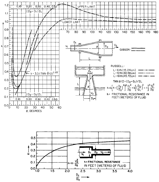
INCREASERS The head lost when there is a sudden increase in pipe diameter, with veloc-
ity changing from V
1
to V
2
in the direction of flow, can be calculated analytically. Computed
results have been confirmed experimentally to be true to within ;3%. The head loss is
expressed as shown, with K computed to be equal to unity:
(23)
The value of K is also approximately equal to unity if a pipe discharges into a relatively
large reservoir. This indicates that all the kinetic energy is lost and V
2
equals zero.
The loss of head for a gradual increase in pipe diameter when the flow is through a dif-
fuser can be found from Figure 39 and Table 6A. The diffuser converts some of the kinetic
V
2
1
>2g
h K
1V
1
V
2
2
2
2g
K c1 a
D
1
D
2
b
2
d
2
V
1
2
2g
K ca
D
2
D
1
b
2
1 d
2
V
2
2
2g
30.05 m
0.56 28.39 0.062 0.089 0.023 0.093 0.89
πh
f
h
fs
h
fd
h
f 1
h
f 2
h
f 3
h
f4
h
f5
98.34 ft
1.84 92.9 0.020 0.29 0.077 0.30 2.91
πh
f
h
fs
h
fd
h
f 1
h
f 2
h
f 3
h
f4
h
f5
h
f5
2.1
2.88
2
2 9.807
0.89 m
h
f5
2.1
9.44
2
2 32.17
2.91 ft
K 100 0.021 2.1
352V
3510.0189 4.81 ft>s 6 9.44 ft>s
K l00f
T
1
2
h
f4
0.22
2.88
2
2 9.807
0.093 m
h
f4
0.22
9.44
2
2 32.17
0.30 ft
K 10.62 0.021 0.22
f
T
0.021
K 8f
T
11.10>1.5002
4
10.62f
T
b 1, u 0, K 8f
T
h
f3
0.15
1.75
2
2 9.807
0.023 m
h
f3
0.15
5.73
2
2 32.17
0.077 ft
K 8 0.019 0.15
b b 1, u 0, k 8f
T
ab
d
1
d
2
1
h
f 2
0.57
1.57
2
2 9.807
0.089 m
8.1 PUMPING SYSTEMS AND SYSTEM-HEAD CURRVES 8.65
FIGURE 40 Resistance coefficients for reducers (Hydraulic Institute Engineering Data Book, Reference 5)
energy to pressure.Values for the coefficient used with Eq. 23 for calculating head loss are
shown in Figure 39. The optimum total angle appears to be 7.5°. Angles greater than this
result in shorter diffusers and less friction, but separation and turbulence occur. For
angles greater than 50°, it is preferable to use a sudden enlargement.
REDUCERS Figure 40 and Table 6A give values of the resistance coefficient to be used for
sudden reducers.
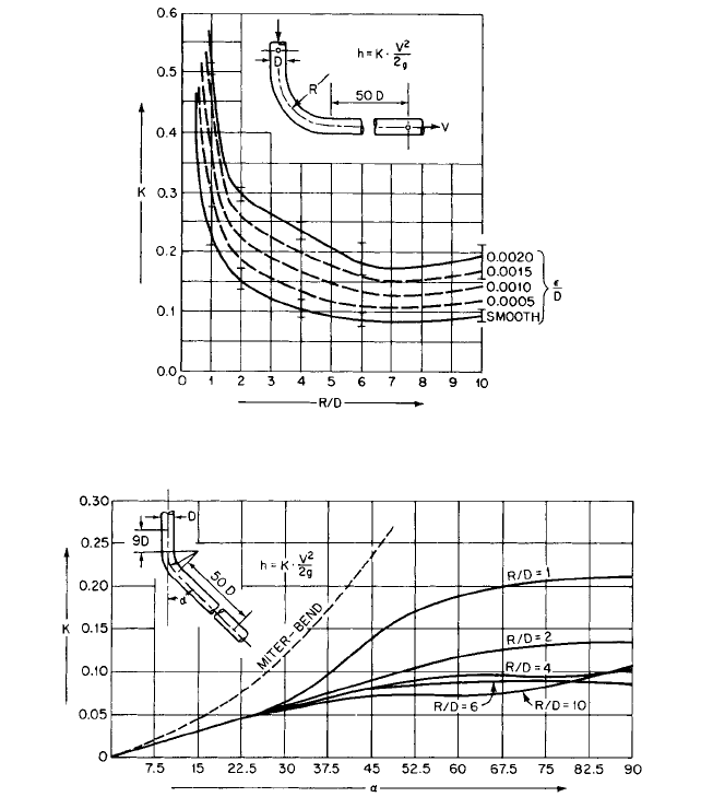
BENDS Figure 41 may be used to determine the resistance coefficient for 90° pipe bends
of uniform diameter. Figure 42 gives resistance coefficients for bends that are less than
90° and can be used for surfaces having moderate roughness such as clean steel and cast
iron. Figures 41 and 42 are not recommended for elbows with R/D below 1. Tables 6D and
7 give values of resistance coefficients for miter bends.
FIGURE 39 Resistance coefficients for increasers and diffusers (D in or ft [m]; V ft/s [m/s]) (Hydraulic
Institute Engineering Data Book,
Reference 5)
8.66 CHAPTER EIGHT
FIGURE 42 Resistance coefficients for bends of uniform diameter and smooth surface at Reynolds number L 2.25
10
5
(Hydraulic Institute Engineering Data Book, Reference 5).
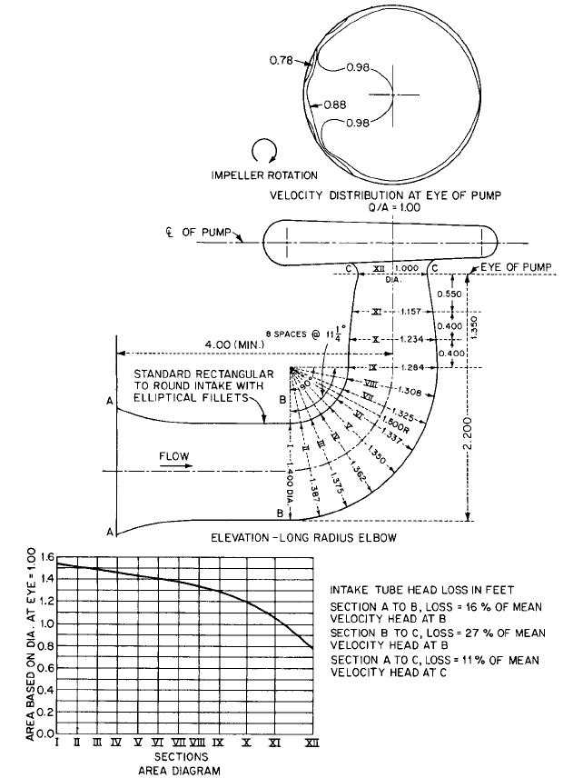
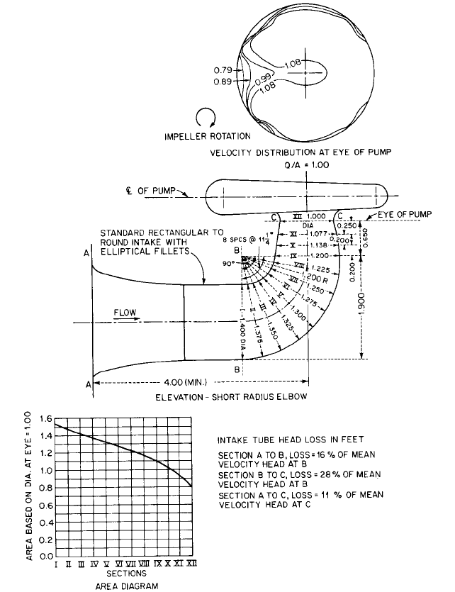
PUMP SUCTION ELBOWS
Figures 43 and 44 illustrate two typical rectangular to round reduc-
ing suction elbows. Elbows of this configuration are sometimes used under dry-pit verti-
cal volute pumps. These elbows are formed in concrete and are designed to require a
minimum height, thus permitting a higher pump setting with reduced excavation. Figure
43 shows a long-radius elbow, and Figure 44 a short-radius elbow. The resulting velocity
distribution into the impeller eye and the loss of head are shown for these two designs.
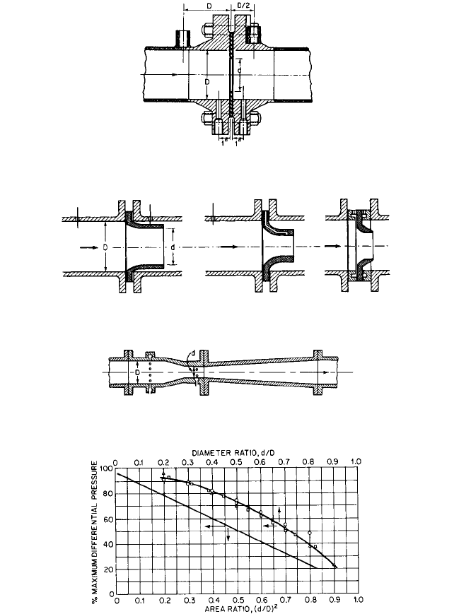
METERS Orifice, nozzle, and venturi meters (Figures 45
—
47) are used to measure rate of
flow. These meters, however, introduce additional loss of head into the pumping system.
Each of these meters is designed to create a pressure differential through the primary ele-
ment. The magnitude of the pressure differential depends on the velocity and density of
the liquid and the design of the element. The primary element restricts the area of flow,
increases the velocity, and decreases the pressure.An expanding section following the pri-
FIGURE 41 Resistance coefficients for 90° bends of uniform diameter (Hydraulic Institute Engineering Data
Book,
Reference 5)
8.67
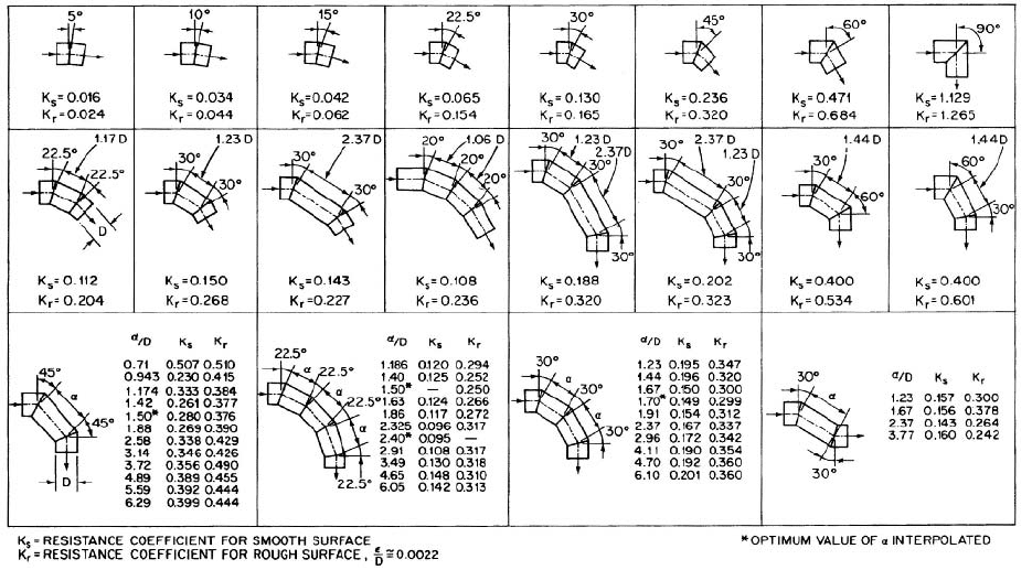
TABLE 7 Resistance coefficients for miter bends at reynolds number 2.25 10
5
Source: Hydraulic Institute Engineering Data Book, Reference 5
8.68 CHAPTER EIGHT
FIGURE 43 Head loss in a long-radius pump suction elbow (in 25.4 mm) (Reference 16)
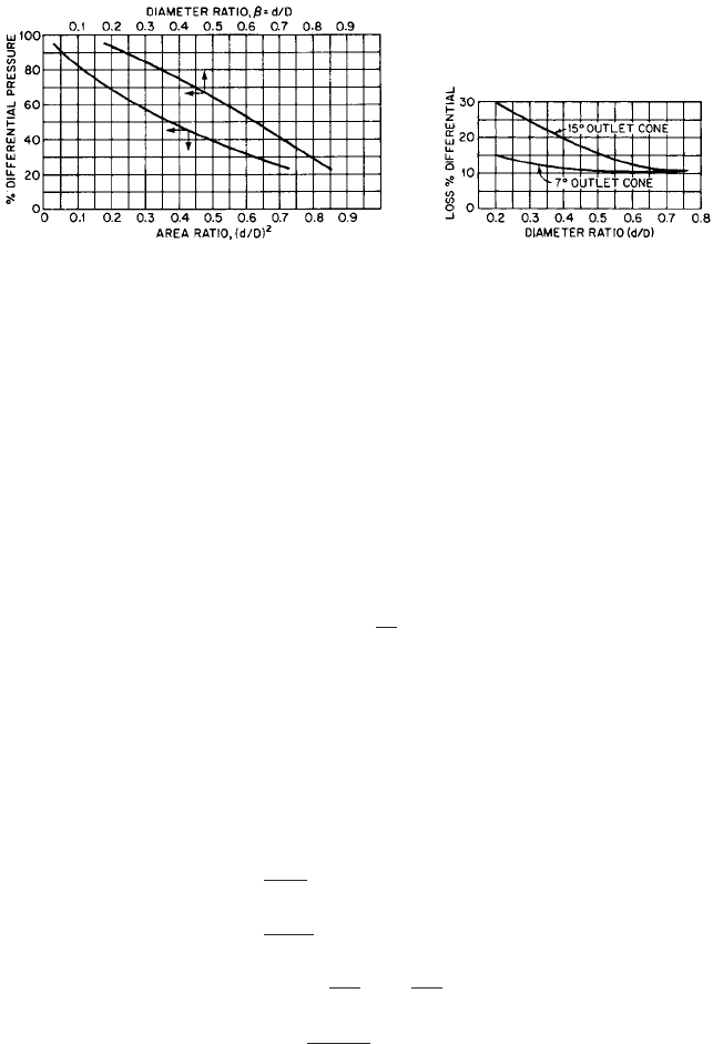
mary element provides pressure head recovery and determines the meter efficiency. The
pressure differential between inlet and throat taps measure rate of flow; the pressure dif-
ferential between inlet and outlet taps measures the meter head loss (an outlet tap is not
usually provided). Of the three types, venturi meters offer the least resistance to flow, and
orifice meters the most.
8.1 PUMPING SYSTEMS AND SYSTEM-HEAD CURRVES 8.69
FIGURE 44 Head loss in a short-radius pump suction elbow (in 25.4 mm) (Reference 16)
When meters are designed and pressure taps located as recommended,
6
Figures 48
—
50
may be used to estimate the overall pressure loss. In these figures, the loss of pressure is
expressed as a percentage of the differential pressure measured at the appropriate taps
and values are given for various sizes of meters. This loss of pressure is also the meter
total head, or energy loss, because there is no change in velocity head if the pipe inside
diameters are the same at the various measuring points.The meter loss of head should be
in units of feet (meters) of liquid pumped if other system losses are expressed this way.
8.70 CHAPTER EIGHT
FIGURE 45 Thin-plate, square-edged orifice meter, showing alternate locations of pressure taps (Reference 6)
FIGURE 46 Shapes of flow nozzle meters and locations of pressure taps (Reference 6)
FIGURE 47 Herschel-type venturi meter, showing locations of pressure taps (Reference 6)
FIGURE 48 Overall pressure loss across thin-plate orifices (Reference 6)
Reference 6 should be consulted for information concerning formulas and coefficients for
calculating differential pressure versus rate of flow.
Screens, Perforated Plates, and Bar Racks Obstructions to the flow of liquid in the
form of multiple orifices uniformly distributed across an open or closed conduit may be
used to remove solids, throttle flow, and produce or reduce turbulence. They may be used
8.1 PUMPING SYSTEMS AND SYSTEM-HEAD CURRVES 8.71
FIGURE 49 Overall pressure loss across flow nozzles
(Reference 6)
FIGURE 50 Overall pressure loss across
venturi tubes (Reference 6)
upstream or downstream from a pump, depending on their purpose, and they therefore
introduce a loss of head that must be accounted for. When an obstruction is placed
upstream from a pump, a significant reduction in suction pressure and NPSH available
can result.
The loss of head results from an increase in velocity at the entrance to the openings,
friction, and the sudden decrease in velocity following the expansion of the numerous liq-
uid jets.The total head loss is a function of the ratio of the total area of the openings to the
area of the conduit before the obstruction, the thickness of the obstruction, the Reynolds
number, and the velocities. Various investigators have determined values for resistance
coefficients that can be multiplied by the approach velocity head to obtain the loss through
these obstructions.According to Idel’chik,
7
loss of head h in feet (meters) may be calculated
from the equation
(24)
where K
1
resistance coefficient
V
1
average velocity in the conduit approaching the obstruction, ft/s (m/s)
g acceleration of gravity, 32.17 ft/s
2
(9.807 m/s
2
)
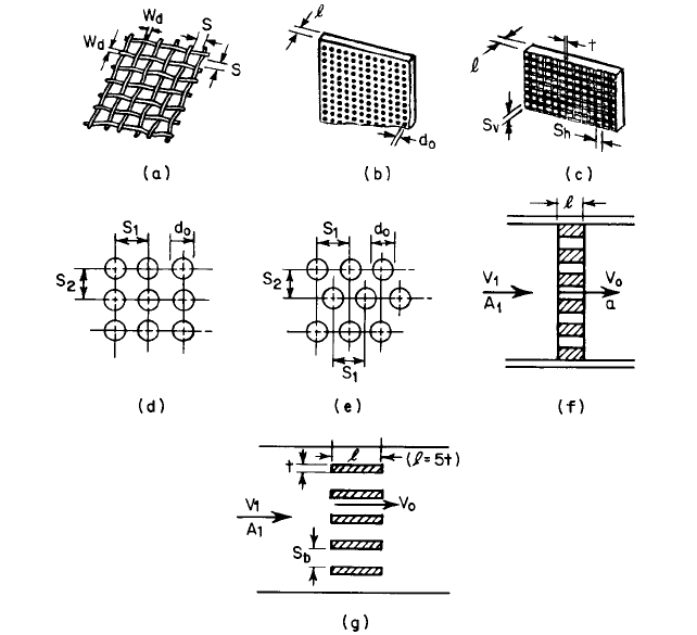
ROUND-WIRE MESH SCREENS For flow having Reynolds numbers equal to or greater than 400,
the resistance coefficient for flow through a round-wire, plain square mesh screen (Figure
51a) may be estimated as a function of percentage of open area using the equations
in USCS units (25a)
in SI units (25b)
(26)
(27)
(28)
where Re screen Reynolds number referred to wire diameter
V
o
velocity through area of rectangular opening 100V
1
/A
r
, ft/s (m/s)
A
r
10011 MW
d
2
2
A
r
100 a
S
S W
d
b
2
K
1
k
0
a1
A
r
100
b a
100
A
r
1b
2
Re
V
o
W
d
v1000
400
Re
V
o
W
d
v12
400
h K
1
V
1
2
2g
8.72 CHAPTER EIGHT
FIGURE 51 Explanation of terms used in Eq. 25–28 and 30–37 and Tables 8 and 9 for calculating resistance
coefficient K
1
(a) round-wire, plain square, mesh screen, (b) round-hole perforated plate, (c) rectangular-grid
perforated plate, (d) perforated plate, holes in vertical columns, (e) perforated plate, staggered holes, (f) perforated
plate, cross section, (g) rectangular bar rack, cross section
W
d
screen wire diameter, in (mm)
v kinematic viscosity, ft
2
/s (m
2
/s)
k
0
1.0 for new, perfectly clean screens to 1.3 for normal screens
A
r
percentage of open area
S square space between wires, in (mm)
M mesh of screen or number of wires per in (mm)
Using water in a flow range of Reynolds numbers of approximately 60 to 800, Pad-
manabhan and Vigander
8
experimented with 1.3- to 12.0-mesh screens, 51.4 to 56% open
area, and found their results to be comparable with those of other investigators. Values of
the coefficient of resistance K
1
, from the Padmanabhan-Vigander tests and others, vary
from 2 decreasing asymptotically to 1 with increase in Reynolds number (Eq. 25) up to
approximately 1000 for 47 to 56% open area. Smaller percentage open area values have
larger coefficients.
Armour and Cannon,
9
using nitrogen as the fluid, tested various types of fine woven
wire screens and derived equations for pressure drop in terms of a friction factor and the
screen Reynolds number. Approach velocities ranged from 0.1 to 30 ft/s (0.03 to 9 m/s),

8.1 PUMPING SYSTEMS AND SYSTEM-HEAD CURRVES 8.73
TABLE 8 Plain square screen geometry
Wire diameter
W
d
, Open Screen constant Screen
Screen mesh size M,in
1
in 10
4
area C
1
,ft
1
10
3
constant
(mm
1
) (mm 10
4
) A
r
,% (m
1
10
3
) C
2
30 30 (1.18 1.18) 9.45 (240) 94.4 2.553 (8.376) 1.553
150 150 (5.91 5.91) 2.36 (59.9) 93.0 8.267 (27.12) 2.594
250 250 (9.84 9.84) 1.69 (42.9) 91.7 16.21 (53.18) 2.934
400 400 (15.7 15.7) 1.00 (25.4) 92.2 30.68 (100.7) 2.680
Source: Reference 9.
resulting in Reynolds numbers from 350 to 275,000. To simply calculations, screen geom-
etry constants C
1
(surface area to unit volume ratio)
2
(pore diameter) and C
2
(screen
thickness) (void fraction)
2
(pore diameter) have been added to the reference authors’
equations to obtain the following expression for screen head loss h in feet (meters):
(29)
where V
1
average velocity in the conduit approaching the screen, ft/s (m/s)
Table 8 lists C
1
and C
2
values for a sample of plain square screens tested by Armour
and Cannon.
PERFORATED PLATES AND BAR RACKS
For flow having Reynolds numbers equal to or greater
than 10
5
, the resistance coefficients for flow through thick, square-edge perforated plates
with round (Figure 51b) or rectangular (Figure 51c) openings and racks with rectangular
cross-section bars (length 5 times thickness; Figure 51g) may be calculated using Eq.
24, Table 9, and the following equations:
(30)
In USCS units (31a)
In SI units (31b)
for plates with round holes (32)
for plates with single hole in center (33)
for plates with square openings (S S
h
S
v
) (34)
for plates with rectangular openings (35)
for any plate or bar rack (36)
for single vertical or horizontal bar racks (37) A
r
100 a
S
b
S
b
t
b
A
r
100
A
o
A
1
A
r
100 c
S
h
S
v
1S
h
t21S
v
t2
d
A
r
100 a
S
S t
b
2
A
r
100 a
d
o
d
1
b
2
A
r
100 a
0.785d
2
o
S
1
S
2
b
D
h
0.004
a
r
or D
h
d
o
1000
D
h
a
3p
or D
h
d
o
12
Re
V
o
D
h
v
10
5
h C
2
V
1
g
18.61vC
1
0.52V
1
2