Pump Handbook by Igor J. Karassik, Joseph P. Messina, Paul Cooper, Charles C. Heald - 3rd edition
Подождите немного. Документ загружается.


8.54 CHAPTER EIGHT
indicated that minor losses vary approximately as the square of the velocity through
the fittings.
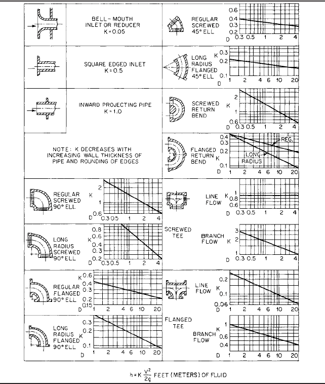
VALVES AND STANDARD FITTINGS
The resistance to flow through valves and fittings may be
found in References 4, 5, 17, and other sources. Losses are usually expressed in terms of
a resistance coefficient K and the average velocity head in a pipe having the same diam-
eter as the valve or fitting. The frictional resistance h in feet (meters) is found from the
equation
(20)
where K resistance coefficient, which depends on design and size of valve or fitting
V average velocity in pipe of corresponding internal diameter, ft/s (m/s)
g acceleration of gravity, 32.17 ft/s
2
(9.807 m/s
2
)
A comparison of the Darcy-Weisbach equation (Eq. 16) with Eq. 20 suggests that K
equals f(L/D), where L is the equivalent length of pipe in feet (meters) and D is the inside
pipe diameter in feet (meters), to produce the same head loss in a straight pipe as through
a valve or fitting. The friction in an “equivalent length of pipe” has been another method
used to estimate head loss through valves and fittings. Values of the ratio L/D have been
experimentally determined. This ratio multiplied by the inside diameter of a pipe of spec-
ified schedule for the valve or fitting being considered gives the equivalent length of pipe
to use to calculate the head lost.
Loss of head in straight pipe depends on the friction factor or Reynolds number. How-
ever, with valves and fittings, head is lost primarily because of change in direction of flow,
change in cross section, and obstructions in the flow path. For this reason, the resistance
coefficient is practically constant for a particular shape of valve or fitting for all flow con-
ditions, including laminar flow. The resistance coefficient would theoretically be constant
for all sizes of a particular design of valve or fitting except that all sizes are not geometri-
cally similar. The Crane Company has reported the results of tests that show that the
resistance coefficient for a number of lines of valves and fittings decreases with increas-
ing size at flow conditions of equal friction factor and that the equivalent length L/D tends
to be constant for the various sizes at the same flow conditions.
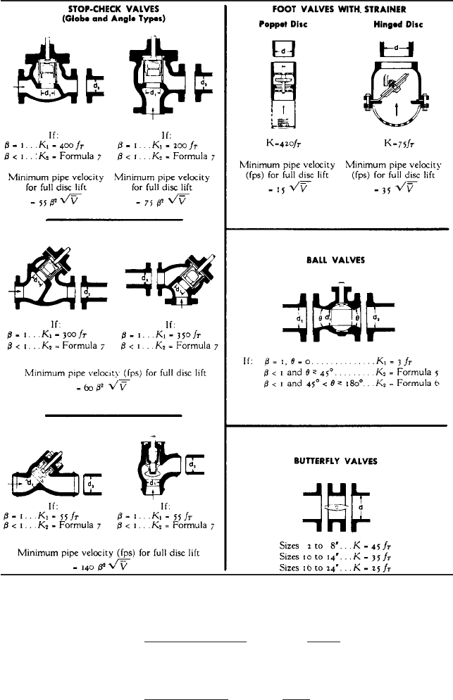
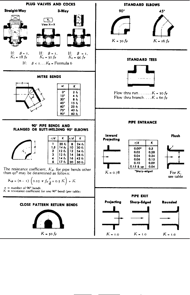
When available, the K factor furnished by the valve or fitting manufacturer should
always be used rather than the value from a general listing. The Hydraulic Institute lists
losses in terms of K through valves and fittings (Tables 5a to 5c); these losses vary with
size of the valve or fitting but are independent of friction factor. The Crane Company pro-
vides a similar listing of K values (Tables 6a to 6e). The latter listing of flow coefficients is
associated with the velocity head V
2
/2g that would occur through the internal diameter of
the schedule pipes for the various ANSI classes of valves and fittings shown in Table 6e.
If the connecting pipe is of a different size or schedule, either use the velocity for the pipe
shown in Table 6a or use the actual pipe velocity head and correct the resistance coeffi-
cient obtained from this table by the multiplier
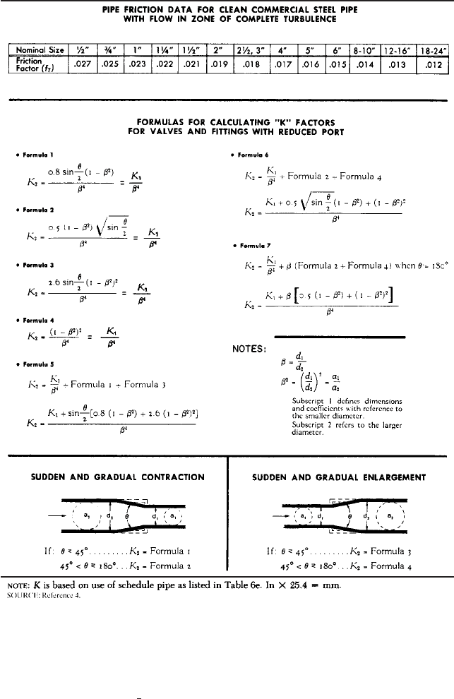
Tables 6 are based on the use of an equivalent length constant for complete turbulent
flow for each valve or fitting shown.This constant is shown as the multiplier of the friction
factor f
T
for the corresponding clean commercial steel pipe with completely turbulent flow.
The product (L/D)(f
T
) is the coefficient K. The friction factors are given in Table 6a for dif-
ferent pipe sizes, or they can be obtained from Figure 31 or 32. If the valve or fitting has a
sudden or gradual contraction, enlargement, or change in direction of flow, appropriate for-
mulas for these conditions are given for the determination of K. If flow is laminar, valve
and fitting resistance coefficients are obtained from Table 6a based on completely turbu-
a
Actual pipe ID
Standard pipe ID
b
4
h K
V
2
2g
8.1 PUMPING SYSTEMS AND SYSTEM-HEAD CURRVES 8.55
NOTE: D nominal iron pipe size in inches (in 25.4 mm). (Hydraulic Institute Engineer-
ing Data Book, Reference 5)
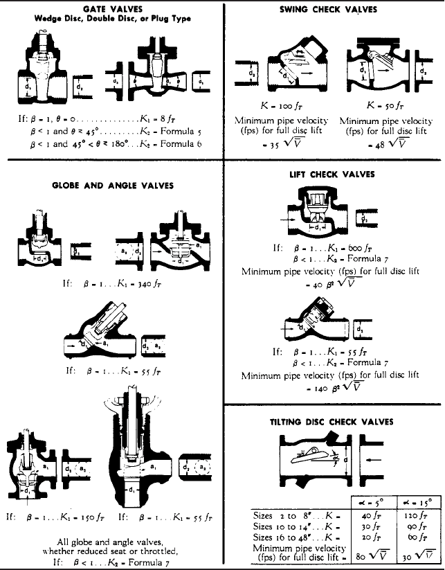
TABLE 5A Resistance coefficients for K for valves and fittings
lent flow, but the pipe frictional loss is calculated using the laminar friction factor f
64/Re instead of f
T
. Also shown in Tables 6 for check valves is the minimum pipe velocity
required for full disk lift for the coefficient of resistance listed (
–
V liquid specific volume
in cubic feet per pound).
Prior to the 15th printing (1976) of the Crane Company Technical Paper 410, and as
shown in the first edition of this text, valve and fitting losses were calculated using an
equivalent length of pipe rather than the coefficient K. The Crane Company states that
this conceptual change regarding the values of equivalent length L/D and resistance coef-
ficient K for valves and fittings relative to the friction factor in pipes has a relatively minor
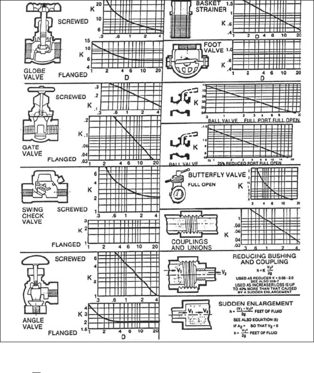
TABLE 5B Resistance coefficients K for valves and fittings
8.56
CHAPTER EIGHT
NOTE: D nominal iron pipe size in inches (in 25.4 mm). For velocities below 15 ft/s (4.6 m/s), check
valves and foot valves will be only partially open and will exhibit higher values of K than shown.
(Hydraulic Institute Engineering Data Book,
Reference 5)
h K
V
2
2g
, ft 1m2 of fluid
effect on most problems dealing with turbulent flow and avoids a significant overstate-
ment of pressure drop in the laminar zone.
Valve Flow Coefficient The loss of head through valves, particularly control valves, is
often expressed in terms of a flow coefficient C
v
in USCS units (K
v
in SI units). The flow
of water in gallons per minute (cubic meters per hour) at 60°F (15.6°C) that will pass
through a valve with a 1-lb/in
2
(1-bar) pressure drop is defined as the flow coefficient for
a particular valve opening. Because loss of head h is a measure of energy loss per unit
weight (force) and because h p/g and head loss varies directly with the square of the
flow through a certain fixed opening, the formulas for flow coefficient are

8.1 PUMPING SYSTEMS AND SYSTEM-HEAD CURRVES 8.57
TABLE 5C Approximate variation for K listed in Tables 5a and 5b
Fitting Range of variation, %
90° elbow Regular screwed 20 above 2-in size
a
Regular screwed 40 below 2-in size
Long radius, screwed 25
Regular flanged 35
Long radius, flanged 30
45° elbow Regular screwed 10
Long radius, flanged 10
180° bend Regular screwed 25
Regular flanged 35
Long radius, flanged 30
T Screwed, line or branch flow 25
Flanged, line or branch flow 35
Globe valve Screwed 25
Flanged 25
Gate valve Screwed 25
Flanged 50
Check valve
b
Screwed 30
Flanged 200
80
Sleeve check valve —— Multiply flanged values by 0.2
to 0.5
Tilting check valve —— Multiply flanged values by 0.13
to 0.19
Drainage gate check —— Multiply flanged values by 0.03
to 0.07
Angle valve Screwed 20
Flanged 50
Basket strainer —— 50
Foot valve
a
—— 50
Couplings —— 50
Unions —— 50
Reducers —— 50
a
In 3 25.4 = mm.
b
For velocities below 15 ft/s (4.6 m/s), check valves and foot valves will be only partially open and
will exhibit higher values of K than shown.
Source: Reference 9.
In USCS units (21a)
also (22a)
In SI units (21b)
also (22b)
where d internal diameter of pipe corresponding to K and as shown in Table 6e, in (mm) and
1 bar 100 kPa. The conversion from the SI flow coefficient to the USCS flow coefficient is
K
v
0.04d
2
>2K
K
v
m
3
>h
A
sp. gr.
bar
C
v
29.9d
2
>2K
C
v
gpm
A
sp. gr.
lb>in
2
{
8.58 CHAPTER EIGHT
TABLE 6A Resistance coefficient K for valves and fittings
EXAMPLE 12 A pumping system consists of 20 ft (6.1 m) of 2-in (51-mm) suction pipe
and 300 ft (91.5 m) of 1 -in (38-mm) discharge pipe, both Schedule 40 new steel. Also
included are a bell mouth inlet, a 90° short radius (SR) suction elbow, a full port suc-
1
2
C
v
1.156K
v
8.1 PUMPING SYSTEMS AND SYSTEM-HEAD CURRVES 8.59
TABLE 6B Resistance coefficient K for valves and fittings
tion gate valve of Class 150 steel, a full port discharge gate valve of Class 400 steel, and
a swing check valve. The valves and fittings are screw-connected and the same size as
the connecting pipe.
Determine the pipe, valve, and fitting losses when 60°F (15.6°C) oil having a specific
gravity of 0.855 is pumped at a rate of 60 gpm (13.6 m
3
/h). Use resistance coefficients
from Tables 5.
The inner diameter of the suction pipe is 2.067 in (52.5mm), and from Figure 32.
0.00087. From Eq. 9,>D
8.60 CHAPTER EIGHT
TABLE 6C Resistance coefficient K for valves and fittings
In USCS units,
In SI units V
m
3
>h
1pipe ID in cm2
2
3.54
13.6
5.25
2
3.54 1.75 m>s
VD– 5.73 2.067 11.8 ft>s in
V
gpm
1pipe ID in inches2
2
0.408
60
2.067
2
0.408 5.73 ft
8.1 PUMPING SYSTEMS AND SYSTEM-HEAD CURRVES 8.61
TABLE 6D Resistance coefficient K for valves and fittings
From Figure 33, Re 1 10
4
, and from Figure 31, f 0.031. From Eq. 16
in USCS units h
fs
0.031
20 12
2.067
5.73
2
2 32.17
1.84 ft
1VD– 0.0919 129.2 11.8 ft>s in2
VD 1.75 0.0525 0.0919 m>s m
8.62 CHAPTER EIGHT
TABLE 6E Pipe schedule for different classes of valves and fittings associated with K
factors used in Tables 6A to 6D
Glass Schedule
300 and lower 40
400 and 600 80
900 120
1500 160
2500 (Sizes to 6 in)
a
XXS
2500 (sizes 8 in and up)
a
160
a
In 25.4 mm.
Source: Reference 4.
1
2
In SI units
The inner diameter of the discharge pipe is 1.610 in (40.89 mm), and from Figure
32, e/D 0.0011. From Eq. 9
in USCS units
in SI units
From Figure 33, Re 1.5 10
4
, and from Figure 31, f 0.030. From Eq. 16
in USCS units
in SI units
The valve and fitting losses from Tables 5 and Eq. 20 are 2-in (51-mm) bellmouth,
K 0.05:
In USCS units
In SI units
2-in (51-mm) SR 90° elbow,
In USCS units
In SI units
2-in (51-mm) gate valve,
In USCS units h
f 3
0.16
5.73
2
2 32.17
0.082 ; 0.021 ft
K 0.16 ; 25%
h
f 2
0.95
1.75
2
2 9.807
0.15 ; 0.044 m
h
f 2
0.95
5.73
2
2 32.17
0.48 ; 0.14 ft
K 0.95 ; 30%
h
f1
0.05
1.75
2
2 9.807
0.0078 m
h
f1
0.05
5.73
2
2 32.17
0.026 ft
h
fd
0.030
91.5
0.04089
2.88
2
2 9.807
28.39 m
h
fd
0.030
300 12
1.610
9.44
2
2 32.17
9.29 ft
1VD– 0.118 129.2 15.2 ft>s in2
VD 2.88 0.04089 0.118 m>s m
V
13.6
4.089
2
3.54 2.88 m>s
VD– 9.44 1.601 15.2 ft>s in
V
60
1.601
2
0.408 9.44 ft>s
h
fs
0.031
6.1
0.0525
1.75
2
2 9.807
0.56 m

8.1 PUMPING SYSTEMS AND SYSTEM-HEAD CURRVES 8.63
In SI units
1 -in (38-mm) gate valve,
In USCS units
In SI units
1 -in (38-mm) swing check valve,
In USCS units
In SI units
The total pipe, valve, and fitting losses are
In USCS units
In SI units
EXAMPLE
13 Solve Example 12 using resistance coefficients from Tables 6.
Suction pipe:
In USCS units (same as in Example 12)
In SI units (same as in Example 12)
Discharge pipe,
In USCS units (same as in Example 12)
In SI units (same as in Example 12)
Valve and fitting losses from Tables 6 and Eq. 20: 2-in (51-mm) bellmouth, K 0.04
In USCS units
In SI units
2-in (51-mm) SR 90° elbow,
(from Table 6A)
In USCS units h
f 2
0.57
5.73
2
2 32.17
0.29 ft
K 30 0.019 0.57
f
T
0.019
K 30 f
T
h
f1
0.04
1.75
2
2 9.807
0.0062 m
h
f1
0.04
5.73
2
2 32.17
0.020 ft
h
fd
28.39 m
h
fd
92.9 ft
h
fs
0.56 m
h
fs
1.84 ft
Total variation ; 10.044 0.0062 0.02 0.322 ; 0.39 m
1.06 30.17 m
0.56 28.39 0.0078 0.044 0.0250 0.0803
πh
f
h
fs
h
fd
h
f1
h
f 2
h
f 3
h
f4
h
f5
Total variation ; 10.14 0.021 0.066 1.02 ; 1.23 ft
3.46 99.05 ft
1.84 92.9 0.026 0.48 0.082 0.263
πh
f
h
fs
h
fd
h
f1
h
f 2
h
f 3
h
f4
h
f5
h
f5
2.5
2.88
2
2 9.807
1.06 ; 0.32 m
h
f5
2.5
9.44
2
2 32.17
3.46 ; 1.0 ft
K 2.5 ; 30%
1
2
h
f4
0.19
2.88
2
2 9.807
0.0803 ; 0.02 m
h
f4
0.19
9.44
2
2 32.17
2.63 ; 0.066 ft
K 0.19 ; 25%
1
2
h
f 3
0.16
1.75
2
2 9.807
0.0250 ; 0.0062 m