Pump Handbook by Igor J. Karassik, Joseph P. Messina, Paul Cooper, Charles C. Heald - 3rd edition
Подождите немного. Документ загружается.

8.3 WATERHAMMER 8.95
as other boundary conditions and head losses must be known. In the solution of water-
hammer problems with computers, the complete pump characteristics are sometimes
approximated by polynomial expressions in which the coefficients of the polynomial are
obtained by fitting a representative curve through several points at specific locations on
the pump characteristics diagram. Pump manufacturers sometimes provide limited infor-
mation to determine such coefficients. However, a comparison between the polynomial val-
ues and the complete pump characteristics diagram indicates serious discrepancies in
some cases, especially in the zone of energy dissipation.To ensure that a serious error does
not result in the computation of the hydraulic transients, care must be exercised in the
use of an approximate polynomial expression as a substitute for the correct complete
pump characteristics.
Complex Piping Systems As noted previously in the basic assumptions, the water-
hammer theory is strictly applicable for a pipeline of uniform characteristics. However,
for waterhammer purposes, a complex piping system can be reduced to a satisfactory
equivalent uniform pipe system. The approximations are made by neglecting the wave
transmission effects at the junctions and points of discontinuity and by utilizing the rigid
water column theory. The pertinent water-hammer equations are then found to be anal-
ogous to those used in electric circuits. In practice, the waterhammer analysis with these
approximations will usually give more conservative results than those obtained experi-
mentally from the pipe system.
2
Available Waterhammer Solutions The waterhammer solutions for pumping systems
with various surge control devices are given in convenient chart form in the references.
These include the following:
1. Hydraulic transients at the pump and midlength of the pump discharge lines for radial-
flow, mixed-flow, and axial-flow pumps with reverse flow passing through the pumps
2. Surge tanks
3. Air chambers
4. Surge suppressors
5. One-way surge tanks
6. Water column separation
The operation of these surge control devices is described next.
Power Failure at Pump Motors
PUMPS WITH NO VALVES AT THE PUMP When the power supply to the pump motors is sud-
denly cut off, the only energy that is left to drive the pump in the forward direction is the
kinetic energy of the rotating elements of the pump and motor. Because this energy is usu-
ally relatively small relative to that required to maintain the flow of water against the
discharge head, the reduction in the pump speed is very rapid. As the pump speed is
reduced, the flow of water in the discharge line is also reduced. As a result of these rapid
flow changes, waterhammer waves of increasing subnormal pressure are formed in the
discharge line at the pump. These subnormal pressure waves move rapidly up the dis-
charge line to the discharge outlet, where complete wave reflections occur. Soon the speed
of the pump is reduced to a point where no water can be delivered against the existing
head. If there is no control valve at the pump, the flow through the pump reverses even
though the pump may still be rotating in the forward direction. The speed of the pump
now drops more rapidly and passes through zero speed. Soon the maximum reverse flow
passes through the pump. A short time later the pump, acting as a turbine, reaches run-
away speed in reverse. As the pump approaches runaway speed, the reverse flow through
the pump is reduced. For radial-flow pumps, this rapid reduction in reverse flow produces
a pressure rise at the pump and along the length of the discharge line. The results of a
large number of waterhammer solutions for a given set of radial-flow (low-specific-speed)
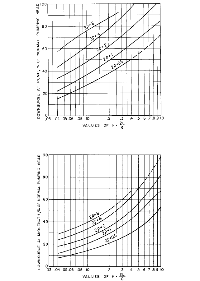
8.96 CHAPTER EIGHT
FIGURE 1 Downsurge at pump
FIGURE 2 Downsurge at midlength
pump characteristics are given in chart form in Figures 1 to 8.These charts furnish a con-
venient method for obtaining the hydraulic transients at the pump and midlength of the
discharge line when no control valves are present at the pump. Although the charts are
theoretically applicable to one particular set of radial-flow pump characteristics, they are
8.3 WATERHAMMER 8.97
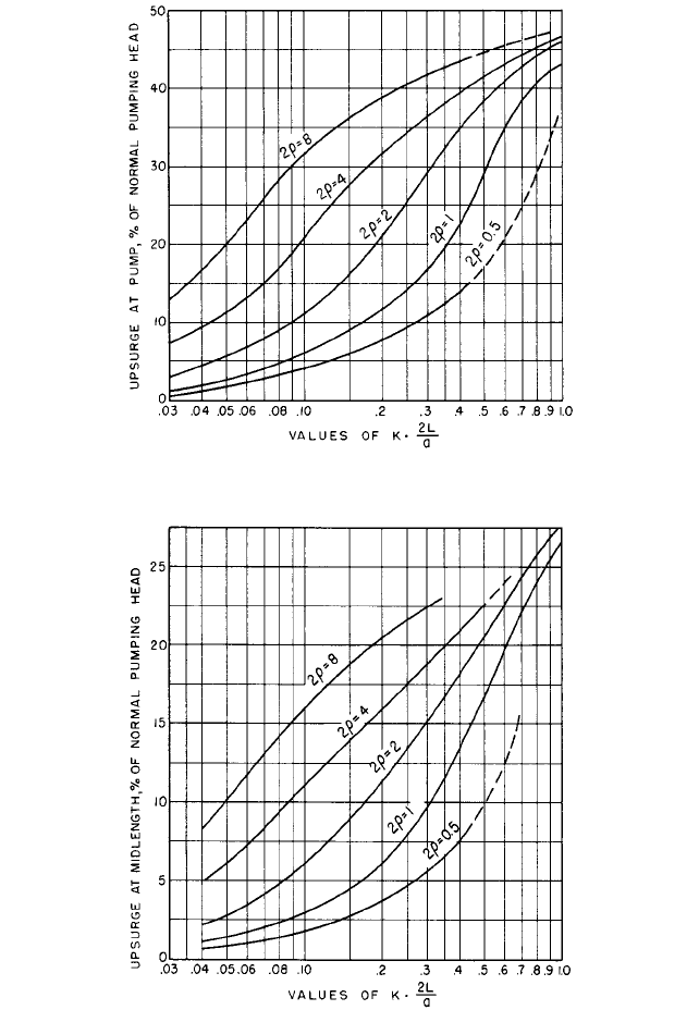
FIGURE 3 Upsurge at pump
FIGURE 4 Upsurge at midlength
useful for estimating the waterhammer effects in any pump discharge line equipped with
radial-flow pumps. The charts are based on two independent parameters: r, the pipeline
constant, and K(2L/a), a constant that includes the effect of pump and motor inertia and
8.98 CHAPTER EIGHT
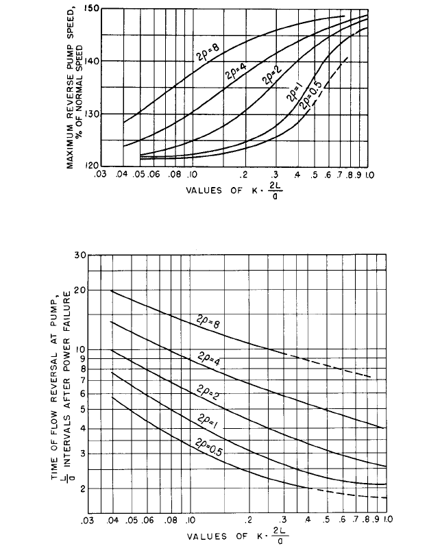
FIGURE 5 Maximum reverse speed
FIGURE 6 Time of flow reversal at pump
the waterhammer wave travel time of the discharge line. If the frictional head in the dis-
charge line during normal operation is more than 25% of the total pumping head and if
water column separation does not occur at any point in the line, the maximum head at
the pump with reverse flow passing through the pumps will usually not exceed the ini-
tial pumping head.
3
PUMPS EQUIPPED WITH CHECK VALVES There are a number of problems associated with the
use of check valves in pump discharge lines. Under steady flow conditions, the pump dis-
charge keeps the check valve open. However, when the flow through the pump reverses
subsequent to a power failure, the check valve closes very rapidly under the action of the
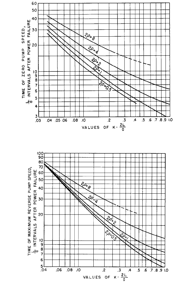
8.3 WATERHAMMER 8.99
FIGURE 7 Time of zero pump speed
FIGURE 8 Time of maximum reverse pump speed
reverse flow and the resulting dynamic forces on the check valve disk. Under these con-
ditions, neglecting pipeline friction, the head rise in the discharge line at the check valve
is about equal to the head drop that existed at the moment of flow reversal. However, if
8.100 CHAPTER EIGHT
the check valve closure upon flow reversal is momentarily delayed because of hinge fric-
tion, malfunction, or the inertial characteristics of the valve, the maximum head rise in
the discharge line at the check valve can be considerably higher. On the other hand, if the
check valve closure can be accomplished slightly in advance of flow reversal, the head rise
in the pump discharge line at the valve is even lower than that obtained with a check
valve that closes at the moment of flow reversal. This feature is utilized by a number of
check valve manufacturers, who provide spring-loaded or lever-arm-weighted devices on
the check valve hinge pins to assist in closing the valve disk before the flow reverses. With
these devices, the hydraulic forces on the valve disk under normal flow conditions must
be sufficient to overcome the spring or lever-arm-weight forces in order to keep the check
valve disk wide open so the head losses at the valve under steady flow conditions will be
a minimum.
Check valves in pump discharge lines may be grouped into two general classes, rapid-
closing and slow-closing. From the previous considerations noted, the primary require-
ment for a check valve upon a power failure is that it should close quickly, before a
substantial reverse flow has been established. When this primary requirement for a fast-
closing check valve cannot be met because of the flow characteristics of the system and the
design of the check valve, an alternative is to provide a device such as a dashpot, which
will slow down or cushion the last portion of the check valve closure. This feature has been
utilized by a number of check valve manufacturers.
CONTROLLED VALVE CLOSURE At most large pumping plant installations, the use of a single-
speed discharge valve closure subsequent to a power failure will usually limit the head
rise in the discharge line to an acceptable value. However, it will be found that with the
optimum single-speed closure, some reverse rotation below the maximum runaway speed
of the unit in reverse will occur. If it is desired from other considerations to prevent or to
limit the reverse speed of the unit, a two-speed valve closure can be used. In such cases,
the discharge valve should close the major portion of its stroke very rapidly up to the
moment that the flow reverses at the pump. It should then complete the remainder of its
stroke at a lower rate in order to limit the pressure rise in the discharge line to an accept-
able valve. At pumping plants where there is more than one pump on the same discharge
line, a compromise must be obtained on the optimum single-speed and two-speed closure
rates for the various combination of pumps that might be in operation at the time of a
power failure.
SURGE SUPPRESSORS
Surge suppressors are sometimes used in pumping plants to control
the pressure rise that occurs in pump discharge lines subsequent to power interruptions.
A typical surge suppressor consists of a pilot-operated valve that opens quickly after a
power interruption either through the loss of power to a solenoid or by a sudden large
pressure reduction or pressure increase at the surge suppressor. This valve provides an
opening for releasing water from the pump discharge line. The valve is later closed at a
lower rate by the action of a dashpot to control the pressure rise as the flow of water is
shut off. A properly sized and field-adjusted surge suppressor can reduce the pressure rise
in the discharge line to any desired value, provided that water column separation does
not occur at other locations in the discharge line. The charts given in Reference 4 can be
used to determine the required flow capacity of the surge suppressor.
The proper field adjustment of a surge suppressor is very important. If the suppressor
opens too rapidly subsequent to a power failure, the downsurge at the pump and along the
discharge line profile will be more than if no surge suppressor is present. As a result, a
water column separation may be produced at some locations in the discharge line by the
premature opening of the surge suppressor. If the suppressor closes too rapidly after the
maximum reverse flow has been established, a large pressure rise will occur.
WATER COLUMN SEPARATION Water column separation in a pump discharge line subsequent
to a power failure at the pump motors occurs whenever the momentary hydraulic gradi-
ent at any location reduces the pressure in the discharge line to the vapor pressure of
water. Whenever this condition occurs, the normal waterhammer solution is no longer
valid. If the subatmospheric pressure condition inside the pipe persists for a sufficient
8.3 WATERHAMMER 8.101
period, the water in the discharge line parts and is separated by a section of water and
vapor. Whenever possible, water column separation should be avoided because of the
potentially high pressure rise that often results when the two water columns rejoin. An
approximate waterhammer solution for water column separation in pump discharge lines
is given in Reference 5.
QUICK-OPENING, SLOW-CLOSING VALVES
A quick-opening, dashpot-controlled, slow-closing
valve can be used to limit the pressure rise at the high points in the discharge line, where
water column separation frequently occurs. When the pressure in the pipeline at the point
of water column separation drops below a predetermined value for which the valve is set,
the valve opens quickly and a small amount of air is admitted in the pipeline. After the
upper water column in the pipeline stops, reverses, and returns to the point of separation
near the valve, the valve should be wide open. The air and water mixes and then the clear
water discharges through the valve. The open valve then provides a point of relief to
reduce the pressure rise caused by the rejoining of the water columns. The valve is later
closed slowly under the action of a dashpot so the head rise that occurs in the discharge
line at the valve location when the reverse flow is shut off is not objectionable. Whenever
these valves are used, precautions should be taken to ensure that they are properly sized,
field-adjusted to the proper opening and closing times, and adequately protected against
freezing.
One-Way Surge Tanks The one-way surge tank, which was introduced by the writer
6
is an effective and economical pressure control device for use at locations where water col-
umn separation occurs. A one-way surge tank is a relatively small tank filled with water
to a level far below the hydraulic gradient. It is connected to the main pipeline with check
valves that are held closed by the discharge line pressure. Upon a power failure, when the
pressure in the discharge line at the one-way surge tank drops below the head corre-
sponding to the water level in the tank, the check valve opens quickly and the tank starts
to drain, filling the void formed by the separation of the water columns. When the flow in
the upper column starts to reverse, the check valves at the one-way tank close before any
appreciable reverse flow is established in the discharge line. Thus there is no pressure
rise when the water columns rejoin. The initial level of water in the one-way surge tank
is usually maintained automatically with float control or altitude valves. It should be
noted that the one-way surge tank does not act during the start-up cycle of the pump dis-
charge line and that it must also be protected against freezing.
AIR CHAMBERS
An effective device for controlling the pressure surges in a long pump dis-
charge line is a hydropneumatic tank or air chamber. The air chamber is usually located
at or near the pumping plant. It can be of any desired configuration and may be placed
in a vertical, horizontal, or sloping position. The lower portion of the chamber contains
water and the upper portion contains compressed air. The desired air and water levels are
maintained with float level controls and an air compressor. When the power failure occurs
at the pump motor, the head and flow developed by the pump decrease rapidly. The com-
pressed air in the air chamber then expands and forces water out of the bottom of the
chamber into the discharge line, thus minimizing the velocity changes and waterhammer
effects in the line. When the pump speed is reduced to the point where the pump cannot
deliver water against the existing head, which is usually a fraction of a second after a
power failure, the check valve at the discharge side of the pump closes rapidly and the
pump then slows down to a stop. A short time later, the water in the discharge line slows
down to a stop, reverses, and flows back into the air chamber. As the reverse flow enters
the chamber, usually through a throttling orifice, the air volume in the chamber decreases
and a head rise above the pumping head occurs in the discharge line. The magnitude of
this head rise depends on the throttling orifice and on the initial volume of air in the air
chamber.
The results of a large number of graphic waterhammer-air chamber solutions are given
in Reference 7. Another presentation of air chamber charts using the rigid water column
theory is given in Reference 8.
8.102 CHAPTER EIGHT
SURGE TANKS
Because it has no moving parts that can malfunction, a surge tank is one
of the most dependable devices that can be used at a pumping plant to reduce water-
hammer resulting from rapid changes of flow in the discharge line subsequent to a power
failure at the pump motor. Following a power failure, the water in the surge tank provides
a nearby source of potential energy that will effectively reduce the rate of change of flow
and the waterhammer in the discharge line. The charts given in Reference 7 provide a
ready means for calculating the surges in the pipeline due to the sudden starting or stop-
ping of a pump.
One of the disadvantages of a conventional surge tank is that because the top of the
tank must extend above the normal hydraulic gradient to avoid spilling, the tank must be
quite tall and expensive at high-head pumping installations. In order to obtain the most
economical surge tank design, care should be given to the proper sizing of the throttling
device at the base of the tank.
NONREVERSE RATCHETS Another device occasionally used for reducing waterhammer in a
pump discharge line upon a power failure is a nonreverse ratchet on the pump and motor
shaft, which prevents the reverse rotation of the pump. This device is effective for control-
ling waterhammer when there is a power failure because of the large reverse flow that can
pass through the stationary impeller. Except on small pumps, experience to date with non-
reverse ratchet mechanisms has been very disappointing. At a number of moderate-size
pump installations where these devices were used, the shock to the pump and motor shaft
system caused by the sudden shaft stoppage created other serious mechanical difficulties.
Automatic Restart of Motors At small unattended pumping plants, it is often desir-
able after a power failure to automatically return the pumps to service as soon as the
power is restored. However, it was found that occasionally, after a very short power out-
age, an induction motor could restart and come quickly up to forward speed while a
reverse flow was still passing through the pump. Under these conditions, waterhammer
in the discharge line is very objectionable. If the pump motor has the capability of restart-
ing under such transient conditions, a time delay or similar device should be installed at
the motor controls so the pump can be started only when it is safe to do so.
Normal Pump Start-Up
WITH CONTROLLED VALVE OPENING
At some pumping plants, the pump is brought up to
speed against a closed valve on the discharge side of the pump. The valve is then opened
slowly, and there is very little waterhammer in the discharge line. However, it will be
found that nearly all of the pump flow in the discharge line is established with only a rel-
atively small valve opening because the head losses across the valve decreases very
rapidly during the opening stroke. For long discharge lines, the head loss and flow char-
acteristics of the valve during the opening stroke must be considered in determining the
optimum rate of opening.
WITH CHECK VALVES At pumping plants where the pipeline is held full with pump check
valves, waterhammer in the discharge line due to a pump start-up can be objectionable
in some cases. If the motor comes up to speed very rapidly, the pump will develop a pres-
sure rise in the discharge line as the sudden increase in flow moves into the line.As noted
previously and in Reference 1, this pressure rise is lower for radial-flow (low-specific-
speed) pumps than for axial-flow (high-specific-speed) pumps (see Section 8.1).
WITH CASING UNWATERED At pumping plants equipped with large pumps, normal starting
of a pump is often performed with the pump casing unwatered. This is accomplished by
depressing the water level below the pump impeller by means of compressed air, which is
admitted into the pump casing with the pump discharge valve closed and the discharge
line full. After the motor has been synchronized on the line, the compressed air in the
pump casing is released, allowing water to re-enter the pump from the suction elbow, after
which the discharge valve is slowly opened. This type of operation has been satisfactory
with most large pumping units, and there are normally no significant waterhammer
8.3 WATERHAMMER 8.103
effects on the discharge line. However, there have been some difficulties with this type of
operation at a few large pump units. In the latter case, when the rising water level in the
suction elbow first reaches the pump impeller, a very fast pumping action occurs within
a few seconds and a severe uplift of the pump and motor from the thrust bearing could
occur at this moment. If the discharge valve is still closed when this fast pumping action
occurs, there is no waterhammer effect in the discharge line.
WITH SURGE OR AIR CHAMBERS With a surge tank or air chamber at the pumping plant, it
makes very little difference whether the increased pump flow is sudden or gradual, inas-
much as the major portion of the sudden increased flow will enter the surge tank or air
chamber. With these devices, the steep front of the pressure rise at the pump is trans-
formed into a smaller pressure rise in the discharge line and a subsequent slow oscillat-
ing movement in the surge tank or air chamber.
NORMAL PUMP SHUTDOWN The pumping installation that produces the least waterhammer
effect in a pump discharge line during a normal pump shutdown is one in which the con-
trol valve on the discharge side of the pump is first closed and the power to the pump
motor then is shut off. If only check valves are in operation on the discharge side of the
pumps and the power to one of several pumps motors connected to the same discharge
line is cut off, the flow at the pump that has been shut down will reverse rapidly and the
check valve will close rapidly. The use of antislam or slow-closing features at the check
valves will reduce the waterhammer effect in the discharge line.
CONCLUSIONS ______________________________________________________
A variety of waterhammer control devices for pumping plants are available to the
designer. In most cases, the experienced designer can narrow the choice of the most suit-
able device to a few practical alternatives. A prior knowledge of the available waterham-
mer solution for these devices will reduce the amount of detailed computational work that
must be done to determine the critical hydraulic transient effects.
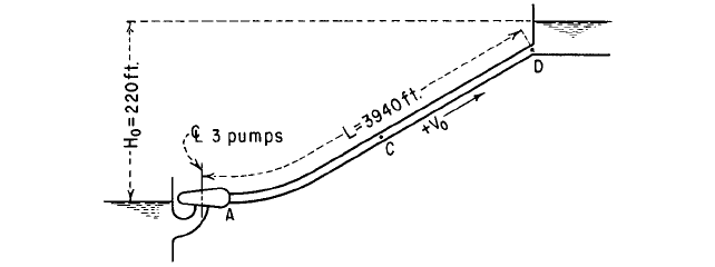
EXAMPLE
Consider a power failure at the pumping plant installation shown in Fig-
ure 9. This installation consists of three pumps that discharge into a steel pipeline.
Aside from isolation valves, there are no check valves in the system. The basic data for
this installation are as follows:
V
0
6.03 ft>s 1for three pumps2; H
0
H
R
220 ft
D 32 in; e 3>16 in; Q
0
Q
R
33.7 ft
3
>s 1for three pumps2
FIGURE 9 Pipeline profile
8.104 CHAPTER EIGHT
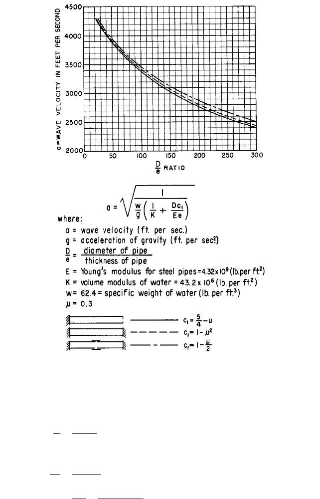
FIGURE 10 Pressure wave velocity in steel pipes
400-hp motors at each pump
2r
aV
0
gH
0
13000216.032
132.2212202
2.55
2L
a
2139402
3000
2.63 s
a 3000 ft>s from Figure 10
D
e
32
0.1875
171
N
R
1760 rpm; h
R
0.847
WR
2
of each pump and motor 385 lb-ft
2