Pump Handbook by Igor J. Karassik, Joseph P. Messina, Paul Cooper, Charles C. Heald - 3rd edition
Подождите немного. Документ загружается.


8.74
TABLE 9 Values of resistance coefficient K
1
for perforated plates and bar racks
A
r
/100 or A
o
/A
1
l/Dh 0.02 0.04 0.06 0.08 0.10 0.15 0.20 0.25 0.30 0.40 0.50 0.60 0.70 0.80 0.90 1.0
0 7000 1670 730 400 245 96.0 51.5 30.0 18.2 8.25 4.00 2.00 0.97 0.42 0.13 0
0.2 6600 1600 687 374 230 94.0 48.0 28.0 17.4 7.70 3.75 1.87 0.91 0.40 0.13 0.01
0.4 6310 1530 660 356 221 89.0 46.0 26.5 16.6 7.40 3.60 1.80 0.88 0.39 0.13 0.01
0.6 5700 1380 590 322 199 81.0 42.0 24.0 15.0 6.60 3.20 1.60 0.80 0.36 0.13 0.01
0.8 4680 1130 486 264 164 66.0 34.0 19.6 12.2 5.50 2.70 1.34 0.66 0.31 0.12 0.02
1.0 4260 1030 443 240 149 60.0 31.0 17.8 11.1 5.00 2.40 1.20 0.61 0.29 0.11 0.02
1.4 3930 950 408 221 137 55.6 28.4 16.4 10.3 4.60 2.25 1.15 0.58 0.28 0.11 0.03
2.0 3770 910 391 212 134 53.0 27.4 15.8 9.90 4.40 2.20 1.13 0.58 0.28 0.12 0.04
3.0 3765 913 392 214 132 53.5 27.5 15.9 10.0 4.50 2.24 1.17 0.61 0.31 0.15 0.06
4.0 3775 930 400 215 132 53.8 27.7 16.2 10.0 4.60 2.25 1.20 0.64 0.35 0.16 0.08
5.0 3850 936 400 220 133 55.5 28.5 16.5 10.5 4.75 2.40 1.28 0.69 0.37 0.19 0.10
6.0 3870 940 400 222 133 55.8 28.5 16.6 10.5 4.80 2.42 1.32 0.70 0.40 0.21 0.12
7.0 4000 950 405 230 135 55.9 29.0 17.0 10.9 5.00 2.50 1.38 0.74 0.43 0.23 0.14
8.0 4000 965 410 236 137 56.0 30.0 17.2 11.1 5.10 2.58 1.45 0.80 0.45 0.25 0.16
9.0 4080 985 420 240 140 57.0 30.0 17.4 11.4 5.30 2.62 1.50 0.82 0.50 0.28 0.18
10 4110 1000 430 245 146 59.7 31.0 18.2 11.5 5.40 2.80 1.57 0.89 0.53 0.32 0.20
Note: l thickness of perforated plate or length of bars, ft (m); D
h
, A
r
, A
o,
and A
1
are as defined following Eq. 37.
Source: Reference 7.
8.1 PUMPING SYSTEMS AND SYSTEM-HEAD CURRVES 8.75
where Re Reynolds number referred to hydraulic diameter
V
O
velocity through area of opening, ft/s (m/s)
D
h
hydraulic diameter ( diameter if openings are round holes), ft (m)
v kinematic viscosity, ft
2
/s (m
2
/s)
a area of single opening, in
2
(mm
2
)
p perimeter of single opening, in (mm)
d
O
diameter of hole, in (mm)
A
r
percentage of open area
S
1
horizontal spacing of holes, in (mm)
S
2
vertical spacing of holes, in (mm)
d
1
diameter of approach, in (mm)
S
h
horizontal apace between vertical bars, in (mm)
S
v
vertical space between horizontal bars, in (mm)
t thickness of plate laths or bars, in (mm)
A
O
total area of openings, ft
2
(m
2
)
A
1
total area of approach, ft
2
(m
2
)
S
b
space between single vertical or horizontal bars, in (mm)
The loss of head through perforated plates may also be calculated by using an orifice
coefficient C, as suggested by Smith and Van Winkle
10
and Kolodzie and Van Winkle.
11
Test
results using air and other gases with equilateral-triangle pitch perforated plates are
shown in Table 10 for Reynolds numbers 400 to 20,000. Using single-orifice relations, the
following expression equates flow rate to pressure drop:
(38)
where v flow rate, ft
3
/s (m
3
/s)
C orifice coefficient from Table 10
A
O
total area of openings, ft
2
(m
2
)
g acceleration of gravity, 32.17 ft/s
2
(9.807 m/s
2
)
P pressure drop, lb/ft
2
(N/m
2
)
g specific weight (force) of liquid, lb/ft
3
(N/m
3
)
A
r
percentage of open area
The resistance coefficient K
1
and the orifice coefficient C may be interchanged in Eqs.
24 and 38 for loss through perforated plates:
(39)
(40) K
1
1 a
A
r
100
b
2
C
2
a
A
r
100
b
2
C
b
1 a
A
r
100
b
2
K
1
a
A
r
100
b
2
v CA
o
R
2g¢P
g c1 a
A
r
100
b
2
d

8.76
TABLE 10 Orifice coefficients C for equilateral-triangle pitch perforated plates
l/D
h
Pitch/D
h
Re 0.33 0.43 0.50 0.52 0.65 0.75 0.80 1.0 2.0
2.0 400
—
4000 0.74
—
0.69 0.75
—
0.71 0.76
—
0.74
—
0.79
—
0.85 0.82
—
0.86 0.83
—
0.87 0.84
—
0.89 0.77
—
0.92
2.0 4000
—
20,000 0.69 0.71 0.74 0.77 0.85 0.86 0.87 0.89 0.92
3.0 400
—
4000 0.70
—
0.67 0.72
—
0.68 0.73
—
0.72
—
0.75
—
0.81 0.76
—
0.82 0.77
—
0.84 0.78
—
0.85 0.70
—
0.87
3.0 4000
—
20,000 0.67 0.68 0.72 0.74 0.81 0.82 0.84 0.85 0.87
4.0 400
—
4000 0.71
—
0.66 0.72
—
0.67 0.72
—
0.69
—
0.73
—
0.77 0.74
—
0.79 0.75
—
0.81 0.76
—
0.53 0.69
—
0.84
4.0 4000
—
20,000 0.66 0.67 0.69 0.72 0.77 0.79 0.81 0.88 0.84
5.0 400
—
4000 0.68
—
0.65 0.69
—
0.66 0.7
—
0.68
—
0.72
—
0.76 0.73
—
0.77 0.74
—
0.78 0.75
—
0.81 0.65
—
0.82
5.0 4000
—
20,000 0.65 0.66 0.68 0.71 0.76 0.77 0.78 0.81 0.82
Note: Pitch/D
h
pitch-to-hole-diameter ratio; l/D
h
plate-thickness-to-hole diameter ratio; Re Reynolds number
Source: References 10 and 11.

8.1 PUMPING SYSTEMS AND SYSTEM-HEAD CURRVES 8.77
Throttling Orifices In addition to measuring flow, orifices can be used to (a) reduce flow
by adding artificial resistance to increase system head, (b) dissipate energy to provide a
desired pressure reduction, and (c) create a high-velocity jet. Orifices for these purposes
are called throttling orifices. In order to maintain a desired minimum flow to prevent dam-
age to a centrifugal pump, a throttling orifice, or a series of throttling orifices, can be used
in the bypass system. The orifice provides additional bypass resistance to maintain the
required bypass flow.
A throttling orifice can be fabricated by drilling a hole in a metal plate (or through bar
stock) that, when inserted between flanges in a pipe (or threaded to pipe), will create the
desired loss of head at the design flow. The resistance coefficient K
1
may be calculated as
if the throttling device were a single hole in a perforated plate, using Table 9 and Eqs. 30,
31, and 33, and the loss of head calculated using Eq. 24.
Energy is dissipated through a throttling orifice because pressure head is converted to
velocity head and this conversion is followed by an inefficient pressure head recovery. Con-
ditions may exist at the orifice vena contracta that could cause vaporization of the high-
velocity, low-pressure liquid jet. Care must be taken in selecting the orifice size to avoid
excessive cavitation noise or choke flow. An orifice cavitation index used to check the ori-
fice selection is described by Tung and Mikasinovic,
12
who also discuss the use of orifices
in series to avoid cavitation.
Although orifices are used to meter flow, accuracy requires that they be fabricated to
standard proportions and that pressure taps be precisely located (Reference 6 and Figure
45). A distinction should be made between meter differential pressure, which is used to
measure flow and is the difference in pressure at the upstream and downstream vena con-
tracta taps, and meter loss of head calculated using the resistance coefficient K
1
, which is
the total overall loss of energy as measured at the upstream tap and past the downstream
vena contracta tap.The loss of head through a standard orifice meter should be calculated
as discussed previously under Meters.
Water Meters and Backflow Preventors Tables 11 and 12 from Reference 17 provide
indicative values of losses through these devices.
PUMP FLOW, HEAD, AND POWER IN VARYING TEMPERATURE SYSTEMS_____
In a pumping system where the weight of liquid pumped is constant, the volumetric flow
rate will vary through system components having different temperatures. An example
would be the condensate and feedwater system in a steam power plant. The following
equation may be used to calculate volumetric flow rate using the specific gravity corre-
sponding to the temperature of the liquid at the location in the system where flow is
required:
In USCS units (41a)
In SI units (4lb)
When calculating the total head required of a pump or pumps to overcome total system
component losses, the actual volumetric flow rate and temperature through each compo-
nent must be used because head loss is a function of velocity and viscosity. Information
provided in this chapter permits computing pipe, valve, and fitting losses in ft
•
lb/lb or ft
(N
•
m/N or m) of liquid passing through the component. If the pump is at a location in the
system where the temperature is different than at the locations where the head losses are
calculated, the total head to be produced by the pump cannot be found by simply adding
the individual component heads.
The pump head required to produce a specific increase in pressure varies inversely
with specific gravity. Therefore, to calculate pump total head, either the component total
m
3
>h
kg>h
998 1sp. gr.2
gpm
lb>h
500 1sp. gr.2

8.78 CHAPTER EIGHT
TABLE 11 Pressure losses for turbine-type water meters
Flow
Pressure Loss, psi, when Meter Size Is:
Rate, gpm 2 in 3 in 4 in 6 in 8 in 10 in 12 in
100 0.8 0.8 0.5
150 3.5 3.5 1.5
200 6.5 6.5 3.0
250 10.0 10.0 4.5
300 14.0 5.5
350 7.0
400 8.0 0.5
450 9.0 1.0
500 10.5 1.2 0.5 0.5
600 2.0 1.0 0.6
700 3.0 1.1 0.7
800 4.0 1.4 0.8
900 5.0 1.7 1.0
1000 6.0 2.0 1.1 0.6
1500 13.0 4.5 2.0 1.0
2000 8.0 3.0 1.6
2500 13.0 4.0 3.0
3000 6.0 4.5
3500 8.5 6.0
4000 11.0 7.7
5000 11.0
6000 18.0
in 25.4 mm gpm .227 = m
3
/h psi .069 = bar
SOURCE: Reference 17
heads must be converted to pump equivalent heads and added together, or all component
losses must be expressed in pressure units so the total of these pressures can be converted
to an equivalent pump head at the pump temperature. From Eqs. 2 and 3, the pump equiv-
alent head is
or
where the subscript 1 denotes the component and the subscript 2 denotes the pump. From
Eq. 6, individual component head losses can be converted to lb/ft
2
(N/m
2
) using
p
1
h
1
g
1
h
2
sp. gr.
1
sp. gr.
2
h
1
h
2
g
1
g
2
h
1

8.1 PUMPING SYSTEMS AND SYSTEM-HEAD CURRVES 8.79
Table 12 Pressure losses for backflow preventers
Flow
Pressure Loss, psi, when Preventer Size Is:
Rate, gpm 2 in 3 in 4 in 6 in 8 in 10 in
100 3.0
150 5.5 1.5
200 2.2 3.0
300 4.0 2.0
400 2.5 3.5
500 3.0 2.5
600 4.0 2.4 4.5
700 5.0 2.6 3.6
800 2.8 3.0
900 3.0 2.8
1000 3.3 2.5 4.0
1200 3.7 2.0 3.5
1400 4.3 2.0 2.9
1600 5.0 2.4 2.7
1800 2.6 2.6
2000 2.8 2.5
2500 3.5 2.5
3000 3.0
3500 3.6
4000 4.0
4500 5.0
in 25.4 mm gpm .227 = m
3
/h psi .069 = bar
SOURCE: Reference 17
Also for Eq. 6,
from which total component losses in lb/ft
2
(N/m
2
) can be converted to an equivalent total
pump head in feet (meters) of liquid to be produced at the pumping temperature.
In a varying temperature system, the positive or negative static head required to raise
or lower the liquid pumped is not simply a difference in elevation. A pump must produce
pressure in a pipe to raise liquid; the pressure required is proportional to the specific
weight (force) of the liquid. The static head required at the pump should be found by
expressing the suction and discharge elevation heads Z as pressures at the pump suction
and discharge connections (corrected to the reference datum plane, if it is not at the pump
centerline elevation) and using actual specific weights (forces) along the pipe. This differ-
ential pressure, in lb/ft
2
(N/m
2
), is then converted to an equivalent static head using the
specific weight (force) or specific gravity at the pump in the above appropriate equations.
When designing a pumping system, there may be several locations for placing a pump
to produce a specified flow rate in lb/h (kg/h) and an increase in pressure in lb/ft
2
(N/m
2
).
If the temperature of the liquid varies at the different pump locations being considered (for
example, before or after a feedwater heater in a steam power plant), the pump total head
in feet (meters) and the volumetric flow rate in gpm (m
3
/h) will vary. Although it is true
TH
P
¢
g
2
g
p1
g
2

8.80 CHAPTER EIGHT
that pump power is proportional to the product of volumetric flow head specific grav-
ity, higher pumping temperature (lower specific gravity) will nevertheless result in higher
pumping power. For the same conditions of weight (or mass) flow and differential pressure,
pump power varies inversely with specific gravity because of the following relationships:
therefore,
then,
Following are formulas for calculating pump input power in brake horsepower or brake
kilowatts:
In USCS units (42a)
(43a)
In SI units (42b)
(43b)
REFERENCES _______________________________________________________
1. Stepanoff, A. J. Centrifugal and Axial Flow Pumps. 2d ed. Wiley, New York, 1948.
2. Moors, J. A. “Criteria for the Development of Siphonic Action in Pumping Plant Dis-
charge Lines.” Paper presented at Hydraulic Division,ASCE Annual Convention, New
York, October 1957.
3. Richards, R. T. “Air Binding in Water Pipelines.” AWWA. J. 53, 1962.
4. “Flow of Fluids through Valves, Fittings, and Pipe.” Technical Paper 410, 15th print-
ing, Crane, New York, 1980.
5. Hydraulic Institute Engineering Data Book, 2nd Edition, 1990, Hydraulic Institute,
Parsippany, NJ www.pumps.org.
6. Fluid Meters. 6th ed. American Society of Mechanical Engineers, New York, 1971.
7. Idel’chik, I. E. Handbook of Hydraulic Resistance. (Translated from Russian.) Israel
Program for Scientific Translations, Catalog No. 1505, 1966, available from U.S.
Department of Commerce, Washington, D.C.
8. Padmanabhan, M., and Vigander, S. “Pressure Drop Due to Flow through Fine Mesh
Screens.” ASCE J. Hydraulics Div., 1978, p. 1191.
kg>h kPa
3,593,000 pump eff. sp. gr.
bkW
m
3
>h m sp. gr.
367.7 pump eff.
lb>h lb>in
2
858,600 pump eff. sp. gr.
bhp
gpm TH sp. gr.
3960 pump eff.
Pump power
1weight or mass flow2 pressure
sp. gr.
Pump power
weight or mass flow
sp. gr.
pressure
sp. gr.
sp. gr.
Total head
pressure
sp. gr.
Volumetric flow
weight or mass flow
sp. gr.
Pump power volumetric flow total head sp. gr.
8.1 PUMPING SYSTEMS AND SYSTEM-HEAD CURRVES 8.81
9. Armour, J. C., and Cannon, J. N. “Fluid Flow Through Woven Screens.” AIChE J. 14:
415, 1968.
10. Smith, P. L., Jr., and Van Winkle, M. “Discharge Coefficients through Perforated Plates
at Reynolds Numbers of 400 to 3000.” AIChE J. 4(3):266, 1958.
11. Kolodzie, P. A., Jr., and Van Winkle, M. “Discharge Coefficients Through Perforated
Plates.” AIChE J. 3(3):305, 1957.
12. Tung, P. C., and Mikasinovic, M.“Eliminating Cavitation from Pressure-Reducing Ori-
fices.” Chem. Eng., December 1983, p. 69.
13. King, H. W., and Brater, E. Handbook of Hydraulics. 6th ed. McGraw-Hill, New
York, 1976.
14. Streeter, V. L. Fluid Mechanics. 5th ed., McGraw-Hill, New York, 1971.
15. Davis, C. V., and Sorensen, K. E. Handbook of Applied Hydraulics. 3d ed. McGraw-Hill,
New York, 1969.
16. U.S. Department of the Interior. Bureau of Reclamation: Turbines and Pumps, Design
Standard No. 6, Washington, D.C., 1956.
17. Rishel, J. B. “Matching Pumps to System Requirements.” Plant Engineering, Decem-
ber 1975, p. 125.
FURTHER READING __________________________________________________
Engineering Data Book. 2nd ed. Hydraulic Institute, Parsippany, NJ, 1979.
Flow Meter Engineering Handbook. 4th ed. Minneapolis-Honeywell Regulator Company,
Brown Instrument Division, Philadelphia, 1968.
Karassik, I. J., and Garter, R. Centrifugal Pumps, McGraw-Hill, New York, 1960.
McNown, J. S. “Mechanics of Manifold Flow.” Proc. Amer. Soc. Civil Engl. 79(258),
August 1953.
Simpson, L. L. “Sizing Piping for Process Plants.” Chem. Eng., June 17, 1968, p. 192
In some systems, the liquid leaving the pump or pumps will divide into a network of
pipes. If the pump is of the centrifugal type, the total pump flow is dependent on the com-
bined system resistance.The total pump flow and flow through each branch can be deter-
mined by the following methods. (Review “Pump Total Head and System-Head Curves” in
Section 8.1.)
BRANCHES IN CLOSED-LOOP SYSTEMS ________________________________
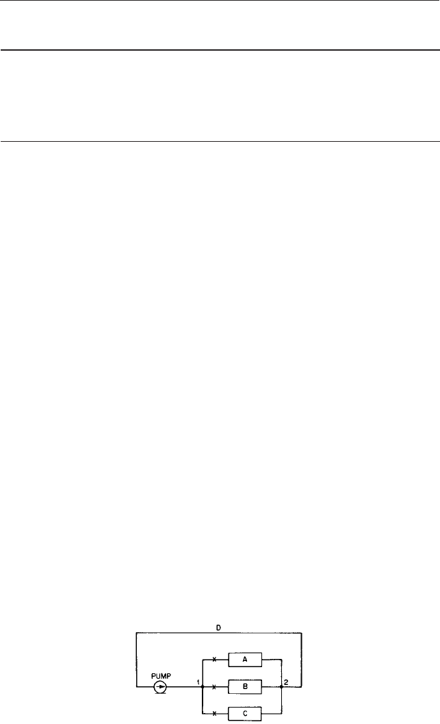
Figure 1 illustrates a pump and network of piping consisting of three parallel branches in
series with common supply and return headers. Junction points 1 and 2 need not be at the
same elevation (provided the liquid density remains constant and the pipes flow full and
free of vapor) because, in a closed-loop system, the net change in elevation is zero. Figure
J. P. MESSINA
8.83
SECTION 8.2
BRANCH-LINE PUMPING
SYSTEMS
FIGURE 1 Closed loop pumping system with branch lines
8.84 CHAPTER EIGHT
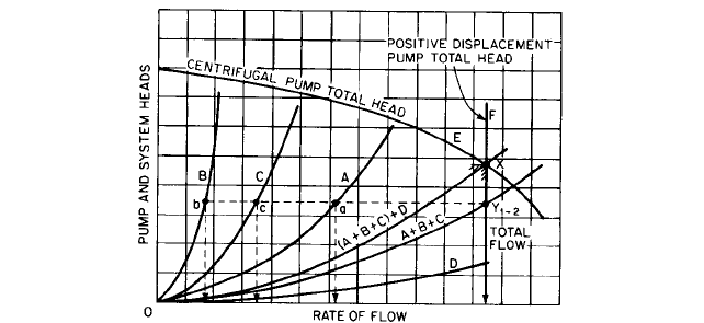
FIGURE 2 System-head curves for pump and branch lines shown in Figure 1 with all valves open
2 shows the system total-head curves for each branch line and header considered inde-
pendent of the others. These curves are constructed for several flow rates by adding the
frictional resistances of the pipes, fittings, and head losses through the equipment serviced
from point 1 to point 2. Curves A, B, C, and D therefore represent the variation in system
resistance in feet (meters) versus flow through each branch and header.
If the valves are open in all branches, the total system resistance, total pump flow, and
individual branch flows are found by the following method. First observe that (a) the total
flow must be equal to the sum of the branch flows, (b) the head loss or pressure drop across
each branch from junction 1 to junction 2 is identical, and (c) the flow divides to produce
these identical head losses. Therefore, at several head points, add together the flow
through each branch and obtain curve A B C. Header D is in series with branches A,
B, and C, and their system heads are added together for several flow conditions to obtain
curve (A B C) D. On curve E, the head-capacity characteristics of a centrifugal
pump, point X represents the pump flow because at this point the system total head and
pump total head are equal. Point Y
12
represents the total head across points 1 and 2, and
this head determines the flow through each branch; consequently points a, b, and c give
individual branch flows. Curve F represents the head-capacity characteristics of a positive
displacement pump (constant capacity) that would produce the same flow conditions.
If valve A is open and valves B and C are closed, Figure 3 shows the construction of the
curves required to determine pump flow point X¿. Obviously the pump flow and branch A
flow are the same. Note that the total flow of point X is less than when all valves are open
as a result of an increase in system head. If all valves were open and the total flow was
obtained by a positive displacement pump having a constant capacity curve F, closing
valves B and C would not change the flow. The system head would, however, increase to
point X– and the head would be greater than for a centrifugal pump having curve E.
Also shown in Figure 3 are the system total-head curves for different combinations of
open valves A, B, and C and the resulting flow caused by a pump having characteristic
curve E. For these various valve combinations, the head differential across the junction
points is found by subtracting the head of the curve D from the system total head for the
condition investigated, for example, point Y¿
12
for only valve A open. The intersection of
a horizontal line through point Y¿
12
and the individual branch curves gives the branch
flow, as illustrated in Figure 2.
BRANCHES IN OPEN-ENDED SYSTEMS _________________________________
Figure 4 illustrates a pump supplying three branch lines that are open-ended and termi-
nate at different elevations. Figure 5 shows the system total-head curves for each branch