Pump Handbook by Igor J. Karassik, Joseph P. Messina, Paul Cooper, Charles C. Heald - 3rd edition
Подождите немного. Документ загружается.

6.2.2 SINGLE-UNIT ADJUSTABLE-SPEED ELECTRIC DRIVES 6.115
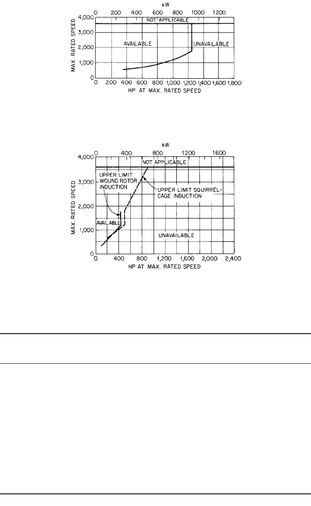
FIGURE 6C Approximate availability of explosion-proof vertical squirrel-cage induction motors (General
Electric)
FIGURE 6D Approximate availability of explosion-proof horizontal squirrel-cage and wound-rotor induction
motors (General Electric)
TABLE 2 Wound-rotor induction motor with liquid rheostat drive data
No. of
Drive Power Voltage Max rated Speed speed
element rating
a
rating speed, rpm range, % Enclosure Mounting points
Motor No limits for Any All established 60 Vertical: shielded Vert. and Infinite
open motors; NEMA by number dripproof, horiz.
see Figure 6A, standard of motor TEFC generally
B, D for poles and not TEWAC
restrictions supply available per
by enclosure frequency Figure 6A
Horizontal:
dripproof,
TEFC,
explosion-
proof per
Figure 6D
Control 25 hp (18.7 kW) For any . . . 60 NEMA 1 Lineup Infinite
min; no motor or singly
stated max secondary Floor
voltage only
a
Drive may be designed for constant torque or for torque varying at the square of the speed.
6.116 CHAPTER SIX
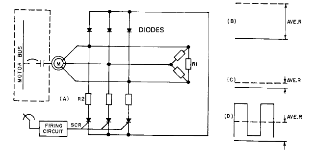
FIGURE 7 Block diagram for wound-rotor induction motor with Tirastat II secondary control power (General
Electric).
liquid rheostat. Figure 7A shows the configuration with the wound-rotor induction motor
and starter identical to those of Figure 4.
The Tirastat controller in its simplest form consists of the components shown in Fig-
ure 7A. Resistors identified as R1 are permanently connected across the motor secondary
phases. Additional resistors (R2) are connected across motor phases through SCR and
diodes.The SCR are individually turned on (become conducting) by minute current pulses
generated by the firing circuit. As the voltage loop across any SCR drops to zero, the SCR
shuts off and does not turn on again until the firing circuit refires it. The diodes allow
return of the current to the motor but block out current reversals to the SCR.
Drive speed varies as a function of changing controller average resistance. Thus, resis-
tance can be varied by adjusting time on-time off ratios in the SCR to give the desired
average resistance. Figure 7B shows controller secondary resistance with the SCR not fir-
ing (conducting). In this condition, the controller resistance value equals the resistance of
R1. Figure 7C shows controller resistance with all SCR firing continuously. The decrease
in resistance is due to additional resistance placed in parallel with resistor R1. Figure 7D
shows controller resistance varying from maximum to minimum in approximately equal
time periods. The average resistance value then approximates half of the sum of R1 and
R2. The time on
—
time off of the SCR can be varied automatically by the controller to pro-
vide the average resistance in the motor circuit necessary to give the desired motor speed.
The motor starter provides normal motor protective functions as well as short-circuit
protection of the motor cables and starter. The Tirastat II controller monitors motor cur-
rent and limits it to some preselected value, such as 150% of normal, under all conditions.
Packaging of the secondary controller is of particular interest. Both packaging and con-
figuration lend themselves to mounting the resistors on or near the control enclosure or
removing them some distance from the enclosure. By placing the resistors outdoors or at
some indoor location away from the operations, heat losses can be released to the envi-
ronment with impunity to operators.
The speed-torque ability of this drive would be very close to that illustrated by Figure
5. The comments contained in the text describing that figure apply equally well here. Table
3 presents significant data useful in drive selection.
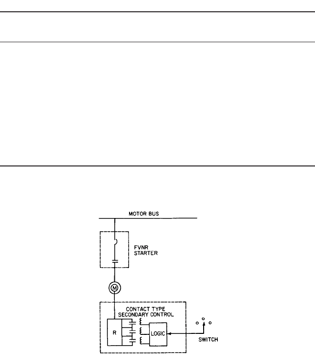
Contact Secondary Controls Many pump drives utilize a very simple combination of
FVNR starter, wound-rotor induction motor, and a form of contact making secondary con-
trol. Figure 8 shows the configuration with a motor and FVNR starter identical with those
of Figures 4 and 7A.
The main difference between this drive and the two described previously lies in the
construction of the secondary controller and the characteristics of the drive. Resistor R in
6.2.2 SINGLE-UNIT ADJUSTABLE-SPEED ELECTRIC DRIVES 6.117
TABLE 3 Wound-rotor induction motor with Tirastat II controller drive data
No. of
Drive Power Voltage Max rated Speed speed
element rating
a
rating speed, rpm range, % Enclosure Mounting points
Motor No limits for Any All established 60 Vertical; shielded Vert. and Infinite
open motors; NEMA by number dripproof, horiz.
see Figure 6A, standard of motor poles TEFC generally
B, D for and supply not available,
restrictions frequency TEWAC
by enclosure available per
Figure 6A.
Horizontal
dripproof, TEFC,
explosion-proof
per Figure 6D.
Control 5 hp (3.7 kW) For any . . . 50 NEMA 1, Lineup Infinite
min. 600 hp motor 70 NEMA 12 or singly
(448 kW) secondary
max. voltage
a
Drive may be designed for constant torque or for torque varying as the square of the speed.
FIGURE 8 Block diagram for wound-rotor induction motor with magnetic secondary control power (General
Electric)
Figure 8 is a three-phase resistor connected across the slip rings of the motor. Its resis-
tance rating is selected to provide minimum motor torque at standstill or adequate torque
at minimum speed. Contacts in the form of magnetic contactors, drum, cam, or dial
switches are closed by a logic device (generally magnetic) to short-circuit part or all of the
resistor. Thus, instead of a modulated or infinitely variable resistor as encountered with
the other two drives, this drive modifies secondary resistance in discrete steps, providing
discrete speed-torque curves instead of an infinite family. The number of speed-torque
curves the control generates will depend directly on the number of contacts provided in the
secondary-control circuit.
Either a manual switch or some automatic contact-making device actuated by the
process can be utilized to actuate the control logic.
Secondary controls are normally packaged in the factory with resistors and contact-
making secondary controller integrally assembled.

6.118 CHAPTER SIX
TABLE 4 Wound-rotor inductions motor with contact-type secondary control drive
data
No. of
Drive Power Voltage Max rated Speed speed
element rating
a
rating speed, rpm range, % Enclosure Mounting points
Motor No limits for Any All established 60 Vertical; shielded Vert. and
open motors; NEMA by number of dripproof, TEFC horiz.
see Figure 6A, standard motor poles generally not
B, D for and supply available,
restrictions frequency TEWAC
by enclosure available per
Figure 6A.
Horizontal
dripproof, TEFC,
explosion-proof
per Figure 6D.
Control No limits For any . . . 75 NEMA 1 Lineup Discrete
motor or singly only
secondary
voltage
a
Drive may be designed for constant torque or for torque varying as the square of the speed.
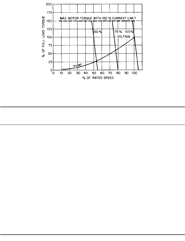
The speed-torque capability of this drive would be very close to that illustrated in Fig-
ure 5, with the exact number of curves determined by the number of contacts of the contact-
making secondary controller and the shape of the curves determined by the resistance
selected. Table 4 presents significant data useful in drive selection.
ADJUSTABLE-FREQUENCY DRIVES ____________________________________
Until recently, the most significant step in the improvement of adjustable drives was to
replace the autotransformer and rectified variable voltage power supply with SCR drives.
Although dc motors are seldom used for pump drives, except in automotive applications
and other special cases, the SCR and PWM adjustable speed dc drives are very highly
developed and available from a number of suppliers.
Pulse Width Modulation Frequency Inverters Adjustable-frequency drives consist of
an adjustable-frequency inverter control and a constant-speed motor, as shown in Figure
9. The inverter control has generally been built in either pulse width modulation or square
wave construction. An inverter control consists fundamentally of a circuit-protective
device, a diode bridge, and an inverter section having an SCR and a firing-control (FC)
section for the SCR, all packaged in a steel enclosure. Special power supplies, motor pro-
tective devices, and electrical protective devices complete the package.
Only low voltages are used to energize the motor bus. A diode bridge rectifies voltage
and an inverter inverts the direct current into an adjustable-frequency adjustable voltage
that varies linearly with frequency. This voltage is not necessarily sinusoidal; it can also
consist of a number of dc pulses of positive or negative polarity, as shown between the
inverter and the motor in Figure 9. The firing controls modulate the width of the pulses
and the number of pulses per half cycle to vary the apparent frequency and to maintain
motor voltage at a constant volts-per-cycle. The firing controls automatically introduce
additional pulses or withdraw pulses as bandwidths reach their limits.
Firing circuits composed of solid-state devices trigger the SCR in accordance with logic
controlled by the setting adjustment of a speed potentiometer (Figure 9) or the signal from
the process. The control provides normal protection of the motor as well as short-circuit
protection of the control, motor, and cables. Also, the control monitors and limits current
drawn by the motor under all conditions to a preadjusted value, such as 150% of normal.
6.2.2 SINGLE-UNIT ADJUSTABLE-SPEED ELECTRIC DRIVES 6.119
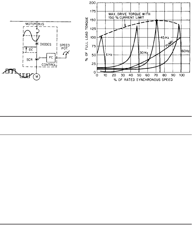
FIGURE 9 Block diagram for ac
adjustable-frequency drive (General
Electric)
FIGURE 10 Torque versus synchronous speed for adjustable-
frequency drive (General Electric)
TABLE 5 Adjustable-Frequency Drive Data
No. of
Drive Power Voltage Max rated Speed speed
element rating
a
rating speed, rpm range, % Enclosure Mounting points
Motor All NEMA 460 or 230 All established 100 Vertical shielded Vert. or Infinite
ratings for by number plus dripproof, TEFC horiz.
open motors; of motor limited per Figure 6B,
see Figure 6B, poles over- explosion-proof
C, D for and supply speed per Figure 6C.
restrictions frequency Horizontal:
by enclosures dripproof, TEFC
per Figure 6B
explosion-proof
per Figure 6D.
Control Up through 460 or 230 Capable of 150 NEMA 1 or Floor Infinite
800 hp (597 producing NEMA 12
kW); higher 150% of
ratings rated
available as frequency
custom-built but at
units reduced
torque
a
Drive may be designed for constant torque or for torque varying as the square of the speed.
Figure 10 displays some representative speed-torque characteristics of the drive uti-
lizing a squirrel-cage induction motor and a representative centrifugal pump. Note that
each characteristic intersects the zero-torque point at a different speed value.This differs
from those of other drives, illustrated in Figures 2 and 5.The steepness of the slope of each
characteristic as it rises from its zero-torque value indicates its low-speed regulation and
provides a clue as to its ability to maintain speed with little fluctuation as load torque
varies slightly. Motor speed is a function of frequency adjustment; the voltage is adjusted
only to accommodate moderate changes in motor impedance.Table 5 lists significant appli-
cation data.
Solid State Adjustable Frequency Inverters The opportunity for adjustable speed for
ac induction motors has been realized by the development of the adjustable frequency con-
trol as well as the more recent vector drives. Similar adjustable speed drives are now
6.120 CHAPTER SIX
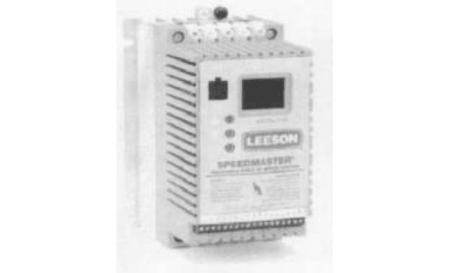
FIGURE 11 Low-power AC inverter (motor controller) for three phase motors with sine wave outputs and an
output frequency range from 1 to 120 Hz (courtesy of Leeson Electric Corp.)
available for the control of switched reluctance (SR) and permanent magnet (PM) brush-
less motors. These three technologies are well suited for pump applications that can ben-
efit from adjustable speed.
There are many manufacturers that offer variable frequency with constant or variable
voltage IGBT-driven PWM inverters for reliable and performance programmable
adjustable speed control of ac induction motors. These drives are available in power up to
the hundreds of horsepower (kilowatts). They offer many standard features that can be
useful for driving pumps. Some of these are summarized as follows:
• Wide input voltage range allowing standardization of motors.
• Dual frequency operation (50 or 60 Hz)
• PWM output for sine wave voltage at selected output frequency
• Constant or variable torque
• High starting torque at programmable linear acceleration/deceleration
• Over-current protection
• Phase to phase and phase to ground short circuit protection
• Maximum output frequency of 120 Hz for double motor speed
• External contacts for other uses
• Analog speed output proportional to frequency
The use of these types of adjustable speed drives provides pump speed ranges up to
nearly twice the base speed of the ac motor. The details of an actual selection of a system
should be discussed with an application from a supplier in order to select the right prod-
uct and size for the pump. An example of a low-power ac inverter is shown in Figure 11.
These classes of solid state adjustable ac motor drives take the 50 or 60 Hz ac line volt-
age from the grid (wide voltage tolerance range OK) and first rectify it into a dc voltage.
Some filter capacitors are sometimes used to attain a smooth dc voltage. Then the dc is
converted into sine waves, one for each phase, at a frequency that is selectable to achieve
the speed of the motor and pump according to the number of poles in the motor. The drive
6.2.2 SINGLE-UNIT ADJUSTABLE-SPEED ELECTRIC DRIVES 6.121
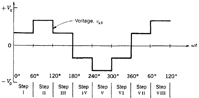
FIGURE 12 AC inverter (6) step simulated sine wave shown for one phase
is designed to maintain a constant volts/Hz relationship. Speed can be controlled to about
10% by inputting the frequency setting.The sine waves can be approximated, as shown in
Figure 12, by the use of a simple six-step transistor switching method. Alternatively, they
can be very precisely generated using a PWM switching topology at a high carrier fre-
quency to achieve a very low-distortion sine wave. The dynamic response of these systems
is sufficient for many pump applications. However, if there are sudden load changes and
speed must be accurately maintained, such as for metering pumps, a higher dynamic
response will probably be needed. For applications that require high acceleration, the con-
stant volts/Hz algorithm will not allow a fast enough dynamic response because the sys-
tem bandwidth will likely be too low.
Another problem with these drives is that they usually need a voltage boost at low
speeds because of the low frequency. This would be a problem only for metering pumps run
over a wide speed range, which is very rare.
Flux Vector Drives The highest performance class of solid-state adjustable speed dri-
ves for ac induction motors are known as flux vector drives. The rectification requirement
of the incoming ac power is the same as is the regeneration of sinusoidal currents for each
of the three phases to power the motor. The very important difference between them is
that the phases are controlled in a closed loop fashion. The control block of the flux vec-
tor drive must receive rotor pole angular position feedback information. With this infor-
mation, the inverter driven ac induction motor can be made to operate like a servomotor.
Most flux vector drives utilize a digital signal processor (DSP) for all of the control func-
tions using the software commands programmed by the supplier (user or supplier can
modify). These include the various control loops such as speed (within 0.5% if required),
acceleration (linear or to a function), current, torque, power, and several more over a very
wide speed range. Drives of this type are available for high power with output frequen-
cies of 800 Hz from several suppliers and up to 3 kHz from a few suppliers.
Flux vector drives can achieve a dynamic response in the 10-millisecond range and
very smooth speed regulation, down to zero with ordinary induction motors. The concept
of the vector control is to observe the present position of the rotor poles and formulate the
control to achieve a dc servomotor performance. The control scheme synthesizes the two
currents in the motor. If the calculation is done correctly, one of the synthesized currents
controls the flux in the motor and the other controls the torque. In other words, one cur-
rent vector in the stator phases lies along the vector of the rotor flux and the other current
vector lies in quadrature or at 90° out of phase. The DSP constantly receives rotor pole
position information and constantly recalculates this relationship at all speeds in spite of
load changes.
6.122 CHAPTER SIX
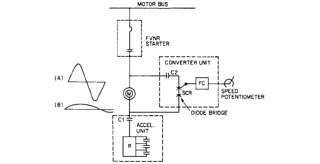
FIGURE 13 Block diagram for modified Kraemer drive
An important feature of flux vector drives is that with simple and minor software mod-
ifications they can easily be used to drive PM brushless motors. The drive has transistor
gate drivers controlled by the commands from the DSP that receives shaft angle position
information from a shaft sensor such as an encoder, resolver, or hall sensors. The poles on
the rotor do not move with respect to the shaft and rotor current (true synchronous oper-
ation without “slip”) as do the poles in the induction motor. It is actually much easier to use
this vector flux vector inverter for a PM brushless than for an ac induction motor. This is
because there are seldom any calculations to required to run the brushless motor unless
phase advance is needed. However, for pump drives, this requirement seems unlikely.
MODIFIED KRAEMER DRIVES__________________________________________
Kraemer drives have been used as heavy industrial drives for many years. Although func-
tioning very successfully, each has three rotating units requiring maintenance, and each
has significant losses.
In recent years, the advance of semiconductors has simplified the drive configuration
to that of Figure 13, which involves an FVNR starter, a wound-rotor induction motor, a
solid-state converter, and an acceleration section. The acceleration section and contactors
1 and 2 can be omitted if the converter rating is large. The FVNR starter switches power
to the motor and protects both the motor and the converter. Contactor C2, if, provided,
serves as a synchronizing contactor between converter and power line and is closed only
when converter and line frequencies and voltages are compatible. This contactor may be
placed on either aide of the converter unit.
Under running conditions, rotor slip energy of low voltage and frequency (Figure 13B)
flows to the low-frequency aide of the converter, The converter unit inverts this voltage to
a fixed line frequency. Thus all motor rotor slip energy except converter unit losses are
returned to the power source, thereby improving drive efficiency.
Under starting conditions, acceleration occurs with contactor C2 open and C1 closed.
Accelerating contactors progressively and automatically short-circuit the resistor H to
allow the motor to accelerate to some preselected speed. When converter output voltage
and frequency match line values, contactor C2 closes and C1 opens automatically. The
drive then operates as already described.
The converter generally consists of a diode bridge and SCRs with their firing circuitry
for inverting. Required auxiliaries, such as special power supplies, complete the package.
6.2.2 SINGLE-UNIT ADJUSTABLE-SPEED ELECTRIC DRIVES 6.123
Generally all control materials are packaged in a single lineup to facilitate building and
installation.
The motor starter provides normal protection of the motor as well as short-circuit pro-
tection of control, motor, cables, and converter. In addition, the converter monitors and lim-
its current drawn from the line under all conditions to a preadjusted value, such as 150%
of normal.
DIRECT-CURRENT MOTOR WITH SCR POWER-SUPPLY DRIVES _____________
General industries use many dc motors with SCR power supplies. These drives perform
very well in the exacting circumstances they normally face. Some of these drives are used
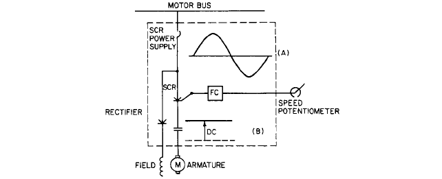
to drive pumps. They are configured as shown in Figure 14 and consist of a dc shunt
wound motor and an SCR power supply.
The dc power supply unit rectifies motor bus voltage to an adjustable dc voltage level,
which in turn energizes the armature of the motor. The second function of the power sup-
ply unit is to rectify motor bus voltage and apply this constant dc voltage to the motor
shunt field. By adjusting the dc voltage to the motor armature, the speed of the motor can
be adjusted to a desired value.
The SCR power supply unit consists primarily of a short-circuit protective device, a
switching contactor, SCR power modules, firing circuitry, a speed regulator, and a shunt
field rectifier. The firing circuitry responds to a low-energy-level speed potentiometer or
some process variable.The SCRs in turn respond to the firing circuitry and translate those
signals into the correct dc voltage to be applied to the armature of the motor. Control cir-
cuitry is included to monitor motor current and limit it to a preselected value, such as
150% of normal.
The SCR power supply unit comes packaged for easy installation in the field.
Speed-torque curves for the drive and for a representative centrifugal pump are shown
in Figure 15. The steepness of the motor torque provides a clue to its stiffness; that is, its
ability to resist speed change because of a change in load torque. Motor torques are lim-
ited to some ceiling, such as 150% of normal, by the current limit circuitry of the drive.
Table 6 provides significant data useful for drive selection.
DRIVE COMPARISONS ________________________________________________
When comparing drives, factors to be considered include the following:
• Drive costs
—
both initial and operating cost. Cost considerations must include not only
initial (installed) cost but also drive efficiency and power factor effects. Power factor may
FIGURE 14 Block diagram for dc motor with SCR power supply
6.124 CHAPTER SIX
FIGURE 15 Torque versus speed for dc motor with SCR power supply
TABLE 6 Direct-current motor with SCR power-supply drive data
Speed No. of
Drive Power Voltage Max rated range, speed
element rating
a
rating speed, rpm % Enclosure Mounting points
Motor Open 240 Rating At Vertical: open/ Vert. or Infinite
horizontal 500 increases least dripproof, horiz.
machines 550 inversely 95 upthrough
can be built with power 300 hp,
at least up rating; can (224 kW)
to 1500 hp match almost totally
(1120 kW); all pump enclosed up
see speed through
Enclosure requirements 200 hp
for other (149 kW)
limits Horizontal:
open/
dripproof,
totally
enclosed up
through
200 hp
(149 kW)
SCR Can be built at Any NEMA . . . At NEMA 1; Floor Infinite
power least up to ac input least NEMA 12
supply 1500 hp voltage; will 95
(1120 kW) match motor
voltage
a
Drive can power either constant-torque toads or those varying as the square of the speed.
be of critical importance in influencing total costs highly dependent on the terms of the
rate structure applied by the power supplier.
• Operating characteristics. All the drives discussed in this section compare favorably and
all are considered generally suitable to perform functionally as pump drives.
• Mechanical features include enclosure, mounting, bearing capabilities, and arrangement
(horizontal, vertical). Features are highly application related.
• Mechanical simplicity is one of most importance to operations personnel. It can consist
of the number of wear points (parts) in rotating and control equipment. The rationale is