Pump Handbook by Igor J. Karassik, Joseph P. Messina, Paul Cooper, Charles C. Heald - 3rd edition
Подождите немного. Документ загружается.

6.136 CHAPTER SIX
Because standard units have no provision for removal and replacement of the working
fluid, all cooling must be provided on the exterior surfaces of the rotating housing. This
becomes a decided limitation if the unit is to be used with constant-torque loads and has
limited the available sizes to some degree.
Hydroviscous Drive As would be expected, this device also follows the centrifugal laws:
power varies as speed raised to the third power and as diameter raised to the second. How-
ever, the density of the working fluid has little or no effect; instead, capacity varies directly
with viscosity. Thus, hydraulic capacity varies with speed, diameter, and viscosity. Mechan-
ical capability is a relatively simple matter of structural design. However, thermal design
is critical. Because power-transmitting capability varies with viscosity, which in turn
varies with temperature, disk design is most important. Free area available for cooling oil
flow varies with disk spacing, output speed, and heat load.
REGULATION________________________________________________________
The output speed of all fluid couplings (hydrostatic drives are not being considered) is
affected, to some degree, by changes in load. Although this may be significant in cases of
single-cylinder, low-speed reciprocating pumps, it is insignificant on multicylinder recip-
rocating and all centrifugal pumps. In these cases, 1% speed regulation is considered nor-
mal. In special cases, regulation has been guaranteed at 0.3%.
TURNDOWN _________________________________________________________
Standard catalog hydrokinetic and hydroviscous units offer the regulation described above
over a 5-to-1 turndown on centrifugal machines and 4-to-1 turndown when driving posi-
tive displacement pumps on constant-pressure systems. Specially designed fluid drives
have been sold that give stable control at 10-to-1 turndown. Hydrodynamic units are lim-
ited primarily by heat dissipation capabilities and range from turndown values of 100 to
1 to 1.2 to 1.
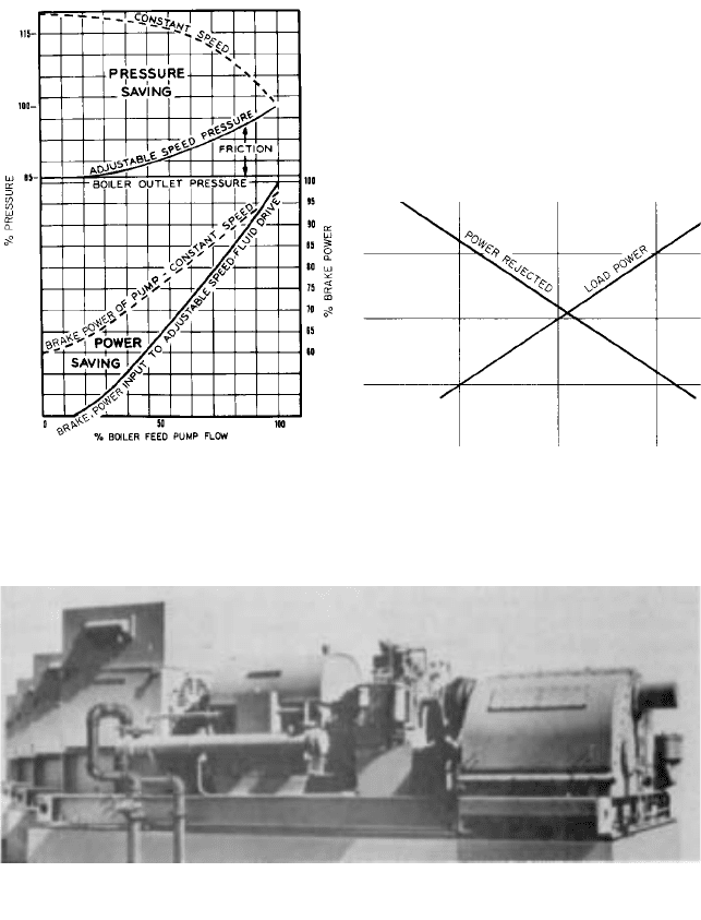
Figure 10 is typical of a boiler-feed pump where a high percentage of the developed
head is relatively constant. In this case, this fixed head is the boiler pressure. The figure
demonstrates the savings in pressure and power realized when this system is used rather
than a feedwater regulating valve.
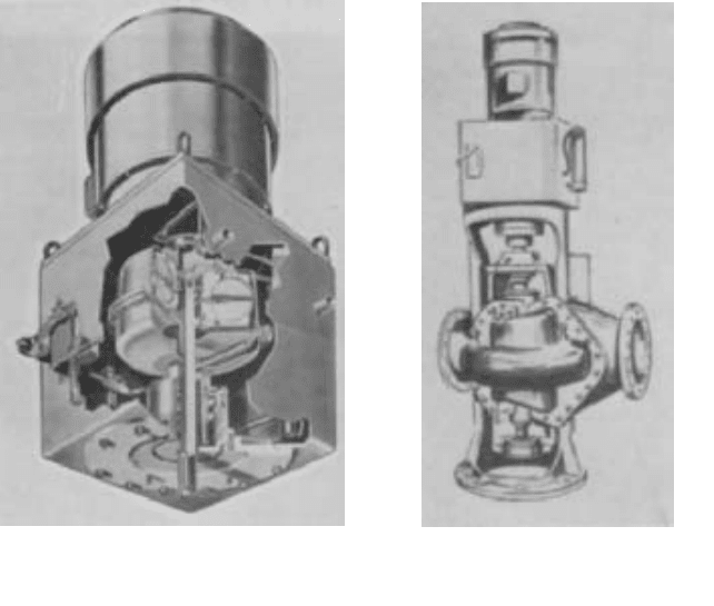
Figure 11 assumes that a positive displacement pump is working on a system where
pressure is constant. Although this type of system is seldom found, it is shown here to
demonstrate that the rapid reduction in fluid drive efficiency does not require overmotor-
ing the pump.Although system efficiency is much poorer than that of a bypass valve, fluid
drives are used to provide no-load starting, isolation of torsional vibrations in reciprocat-
ing pumps, and elimination of the bypass valve in slurry systems where erosion is severe.
Response It must be recognized that all fluid couplings being discussed here are slip
devices. Thus, any demand speed change cannot be accomplished in microseconds or mil-
liseconds. However, the time required to change the torque applied varies from one type
of unit to another.
Hydrokinetic Drive In the scoop-trimming fluid drive, response speed is affected by
many factors.The speed with which oil can be added to the working circuit (a factor of the
size of the oil pumps) or removed from it (a factor of the size of the scoop tube) influences
response capability.
In the leakoff unit, the size of the leakoff ports determines how quickly the unit will
empty. However, the oil pumps must be sized to replace this oil and have additional capac-
ity to fill the coupling in a reasonably short time.
Scoop-control units are limited by the ability of the scoop tube to pump oil from the
reservoir into the working circuit and by the ability of the leakoff ports to return it to the
6.2.3 FLUID COUPLINGS 6.137
FIGURE 11 Positive displacement pump with
constant discharge head
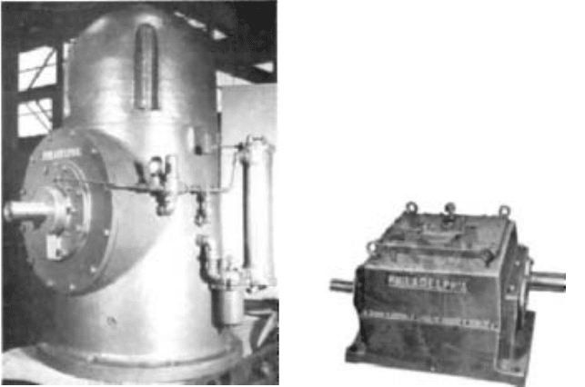
-FIGURE 12 Thirteen fluid drives driving reciprocating pumps on a coal pipeline. The fluid drive absorbs a large
percentage of the pulsations created by the reciprocating pumps and controls their speed to provide proper pipeline
flow (American Davidson).
FIGURE 10 Comparison of adjustable-speed and
constant-speed pressure and power characteristics for a
typical centrifugal boiler-feed pump
reservoir. Some special marine couplings utilize quick-dumping valves, but these are sel-
dom, if ever, used with pump drives.
Obviously the speed at which the scoop tube is moved is also significant. Large polar
moments of inertia (WK
2
values) of the driven equipment will increase response time.
The scoop-trimming coupling offers the best overall response characteristics of the
hydrokinetic drives, and standard catalog machines have normal fill times ranging from
10 to 15 s. They will accomplish 90% of a 10% step speed change in the 40 to 100% speed
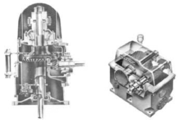
6.138 CHAPTER SIX
FIGURE 14 Fluid drive of Figure 13 mounted on a
vertical-shaft pump (American Davidson)
FIGURE 13 Cutaway view of vertical fluid drive
suitable for operation with vertical pumps. Note the
NEMA P pump flange and output shaft (American
Davidson)
range in 7 to 20 s if coupled to a “normal load inertia.” Special units are in operation where
this change is accomplished in 2 to 6 s.
Hydrodynamic and Hydroviscous Drive Both hydrodynamic and hydroviscous cou-
plings respond very quickly to a change in demand for torque output. Both require a
mechanical motion (change in valve position or change in spacing between disks) followed
immediately by a change in pressure or in film thickness.
In most cases, the torque available for speed change and the WK
2
values involved are
of such a magnitude that the major portion of the response time is caused by inertial
effects rather than by the time required to change torque. This is particularly true in the
deceleration of centrifugal pumps. Unless auxiliary brakes are built-in, none of the hydro-
kinetic, hydrodynamic, or hydroviscous drives can provide dynamic braking. On a demand
to decrease speed, they can at best reduce driving torque to zero. Under these circum-
stances, the only retarding force to slow the inertia of the driven machine is the load it
developed. In the case of centrifugal pumps on fixed systems, this load would fall off as the
cube of speed, and below 40% of full speed, such pumps have an almost insignificant brak-
ing effect.
EFFICIENCY_________________________________________________________
There are two kinds of losses present in hydrokinetic, hydrodynamic, and hydroviscous
couplings. First, we will consider what are termed circulation losses. They are made up of

6.2.3 FLUID COUPLINGS 6.139
bearing friction, windage, and the power required to accelerate the oil in the rotor. On
internal pump units, the power required to drive the oil pump is included. As an average,
these losses represent approximately 1.5% of the unit rating, and for most purposes these
losses may be considered as being constant, regardless of output speed.
Second are slip losses. As is the case on similar slip machines such as mechanical
clutches and eddy-current couplings, the torque on the input shaft equals the torque on
the output shaft. Therefore any reduction in the speed of the output shaft has a directly
related power loss inside the machine. In other words,
The total fluid drive losses are the sum of the two inefficiencies. The complete energy
formula is
In USCS units
In SI units
At maximum designed operating speed (which is usually about 98% of driven speed),
the total coupling efficiency is approximately 96.5%, with 1.5% of the losses being circula-
tion losses and 2% being slip losses. The hydroviscous unit can be operated at 100% dri-
ven speed, but under these conditions it is not a fluid coupling.
Because the circulation losses become relatively insignificant at reduced speeds,
approximate calculations may be made using the formula
CONTROLLERS______________________________________________________
Of the hydrokinetic devices, the scoop-trimming and scoop-control units require that a
mechanical motion be imparted to the scoop tubes for control, and some device must be
furnished to provide this motion. This may be a hand crank on a manual control system.
Simple mechanical systems are often used
—
a typical example is a weighted float with a
rope connected to the scoop tube, controlling level in a tank. However, most installations
utilize electric, electrohydraulic, hydraulic, or pneumatic actuating devices. It is not sur-
prising that the pipeline and refinery industries use electrohydraulic actuators similar to
those used on valves. The electric utility industry prefers pneumatic or electric damper
operators.The only criterion for actuator selection is compatibility with the other elements
of the control system.
The leakoff devices require a signal to the control valve. At present, this is standard-
ized as a hydraulic-pressure signal, although special transducers would permit the use of
other types of signals. The hydrodynamic devices are available with manual level control
(which could be adapted to actuators) or with closed-loop constant-pressure or constant-
temperature systems. All hydroviscous drives utilize oil pressure applied to a piston to
“clamp” or vary the spacing of the disks. This hydraulic pressure may be varied by almost
any type of signal, provided that the proper servos are utilized. Thus the signal may be
electric, hydraulic, or pneumatic.
Efficiency
output speed
input speed
Fluid drive input kilowatts
output kilowatts
output speed>input speed
a
circulation
kilowatt losses
b
Fluid drive input horsepower
output horsepower
output speed>input speed
a
circulation horse-
power losses
b
Slip efficiency
output speed
input speed
100

6.140 CHAPTER SIX
TABLE 1 Variable-speed coupling capacities
Hydrokinetic
Min/max
input hp for Max input hp Hydrodynamic Hydroviscous
Input speed, horizontal- for vertical-shaft min/max input min/max
rpm shaft units
a
units
a
hp
b
input hp
b
720 40,000
—
45,000 .... .... 3,000
—
8,000
900 1,000
—
7,500 6,000 1
—
25 3.000
—
10,000
1,200 1,000
—
14,000 17,000 1
—
30 3,000
—
15,000
1,800 1,000
—
14,000 18,000 1
—
60 3,000
—
20,000
3,600 1,000
—
30,000 29,000 .... 3,000
—
20,000
a
1 hp 0.746kW
b
Horsepowers apply to either horizontal or vertical units.
TABLE 2 Hydrokinetic drive dimensions
Power at 1800 rpm,
input hp (kW) Length, in (cm) Width, in (cm) Shaft height, in (cm)
5 (3.73) 24 (61.0) 15 (38.1) 11 (29.2)
20 (14.9) 39 (99.1) 18 (45.7) 12 (31.7)
50 (37.3) 38 (96.5) 28 (71.1) 19 (48.3)
100 (74.6) 38 (96.5) 28 (71.1) 19 (48.3)
1000 (746) 74 (188) 50 (127) 30 (76.2)
4000 (29811) 102 (259) 62 (157) 42 (107)
1
2
1
2
CAPACITIES AVAILABLE ______________________________________________
Standard catalog variable-speed fluid couplings are available from one or more manufac-
turers in the speeds and powers shown in Table 1. Special designs are available for higher
power ratings.
DIMENSIONS ________________________________________________________
To give some idea of physical dimensions,Table 2 lists approximate dimensions for hydro-
kinetic drives of one U.S. manufacturer. These feature a scoop-trimming coupling and are
probably the largest unit for a given speed and power.
SELECTION AND PRICING_____________________________________________
Because of variations in fluid coupling design for different sizes and speeds, it is virtually
impossible to develop rule-of-thumb methods of estimating costs. The price list of one
major fluid drive manufacturer indicates that prices can range from $60 per horsepower
for sophisticated machines down to $25 per horsepower for others (in 1984 dollars). Fluid
couplings prices can be increased dramatically by specific requirements for exotic controls,
backup pumps and heat exchanger equipment, and other accessories. Because of this fact,
it is recommended that the manufacturers be contacted to obtain even budget prices.
6.2.3 FLUID COUPLINGS 6.141
The basic information required by the manufacturer for selection and pricing is as
follows:
1. Speed and type of driver
2. Power required by the driven machine at, or at least, one operating point
3. Character of driven machine-smooth or pulsating load; how torque requirements
change with speed
4. Cooling medium available and temperature of medium
5. Control type
6. Accessories
7. Special specification requirements
Reasonable budget figures can usually be obtained with items 1 to 3 only.
CONCLUSION _______________________________________________________
Fluid couplings are utilized to drive pumps in virtually all pump applications requiring
variable flow or pressure. They are used primarily to improve efficiency and controllabil-
ity, to permit no-load starting, and to reduce pump and system wear. They are standard-
ized to the degree that units are available to handle most pumping applications. Most
manufacturers stand ready to develop new designs as the requirements of the market-
place change.
6.2.4
GEARS
H. O. KRON
F. L. VAN LANINGHAM
6.143
USE OF GEARS WITH PUMP DRIVES ____________________________________
The main use of gearing in pump drives is to reduce the speed of the prime mover (a motor
or an engine) to the level applicable to the pump. In some cases, however, the gears are
employed to step up the speed because the pump must operate at a speed higher than that
of the prime mover.
There are other jobs that gear drives must perform with pump units. For instance, a
vertical pump may be combined with a prime mover that must operate horizontally (as in
the case of a diesel engine). A right-angle gear set (Figures 1 and 4) can be incorporated
into the drive of such a combination to transmit the power “around the corner” even if the
gears are of a 1:1 ratio and no speed change is involved. See a word of caution concerning
even ratio gears, “Minimizing Gear Noise,” item 9.
At times, too, a gear drive must combine the power shafts of two prime movers; for
example, an electric motor and a diesel engine. This combination is desirable where there
is a need for emergency power in cases of electric power failure. The motor is used ordi-
narily and the diesel is reserved for emergencies. In such an arrangement, the motor may
be mounted vertically on top of the gear drive to drive right through the shaft, whereas the
diesel is geared at right angles to the motor.
Gear drives are also used to vary the speed of a pump. Change gear arrangements (Fig-
ure 2) may be used to vary the gear ratio. Also, numerous types of variable-speed devices,
such as variable-speed pulley belts, friction rollers, hydraulic couplings, hydrostatic and
hydroviscous drives, eddy-current and electric drives, are often utilized.
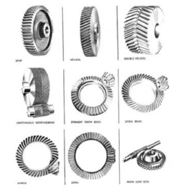
TYPES OF GEARS____________________________________________________
The gears generally used for pump applications are parallel-shaft helical or herringbone
gears and right-angle spiral-bevel gears. Spur gears are used on occasion, particularly in
6.144 CHAPTER SIX
FIGURE 2 Four-speed change gear, variable-speed
drive
FIGURE 1 Spiral-bevel gear, right-angle vertical
pump drive
low-power, low-speed pump drives. Straight bevel and hypoid gears are also occasionally
used in right-angle drives. As in the case of spur gears, straight-bevel gears are limited in
power and speed. Hypoid gears are employed only infrequently for pumps because they
are generally more costly than the other right-angle types.Worm gears, too, are employed
only on occasion, in cases where an overall package requires a compact gear arrangement
or when a high ratio of speeds is called for. Worm gears are limited in power capacity, and
the efficiency of this type of drive is lower than that of other types. Figure 3 shows the var-
ious types of gears.
Parallel-Shaft Gearing A high-speed parallel-shaft gear drive is shown in Figure 5.
HELICAL VERSUS SPUR GEARS
Spur gears transmit power between parallel shafts without
end thrust. They are simple and economical to manufacture and do not require thrust
bearings, but they are generally used only on moderate-speed drives.
One of the first decisions that must be made when considering a parallel-shaft gear
reducer or power transmission drive is whether the gears should be spur or helical and, if
helical, whether they should be single or double. It is generally acknowledged that helical
gears offer better performance characteristics than do spur gears, but because helical
gears, size for size, often are somewhat more expensive, some users have shied away from
them to keep the cost of the gear drive to a minimum. However, cost studies that compared
similar size spur and helical gears found that helical gears are actually a better buy.
The geometries of spur and helical gears are both the involute tooth form. Slice a heli-
cal gear at right angles to its shaft axis and you have the typical spur gear profile.Typical
of a spur gear, however, is that, when driving another spur, its teeth make contact with the
teeth of the mating gear along the full length of the face. The load is transferred in
sequence from tooth to tooth.
A more gradual contact between mating gears is obtained by slanting the teeth in a
way to form helices that make a constant angle
—
a helix angle with the shaft axis. Tooth
contact between the teeth of mating helical gears is gradual, starting at one end and mov-
ing along the teeth so, at any instant, the line of contact runs diagonally across the teeth.
6.2.4 GEARS 6.145
FIGURE 3 Types of gears
The effect of the tooth helix is to give multiple tooth contact at any time. Gear geometry
can be arranged to give from two to six or more teeth at any time.
Because of the greater number of teeth in contact, a helical gear has a greater effective
face width (up to 75% more) than an equivalent spur gear. Also, the effect of the tooth helix
on the profile geometry in the plane of rotation is to make the pinion equivalent to a pin-
ion with a greater number of teeth, thereby increasing its power capacity. A helical gear is
capable of transmitting up to 100% more power than an equivalent spur gear. Further-
more, a helical gear set will give smoother, quieter operation.
The recommended upper limit of pitch line velocity for commercial spur gears is
around 1000 ft/min (300 m/min). The upper limit for equivalent helical gears is about five
times that, or 5000 ft/min (1500 m/min). Of course, as precision goes up, so do the permis-
sible operating speeds for both spur and helical gears. Velocities in the 30,000-ft/min
(9100-m/min) range are not uncommon for helical gears.
In addition to the normal radial loads produced by spur gears, helical gearing also pro-
duces an end thrust along the axis of rotation. The end thrust is a function of the helix
angle: the larger the helix angle, the greater the thrust produced. Mounting assemblies
and bearings for helical gearing must be designed to receive this thrust load.
6.146 CHAPTER SIX
FIGURE 5 High-speed parallel-shaft gear drive
FIGURE 4 Cross section of spiral-bevel vertical
pump drive
DOUBLE HELICAL GEARS
Gears of this type have two sets of opposed helical teeth. Each set
of teeth has the same helix angle and pitch, but the helices have opposing hands of cut.
Thus, the thrust loads in two sets of teeth counterbalance each other and no thrust is
transmitted to shaft and bearings. Also, because end thrust is eliminated, it is possible to
cut the teeth with greater helix angles than is generally used in helical gears. Tooth over-
lap is greater, producing a stronger and smoother tooth action.
The advantages attributed to helical gears are also applicable to double helical gears.
Double helical gearing finds application in high-speed pump applications where a large
helix angle must be combined with tooth sharing and elimination of end thrust for
extremely smooth gear action.
Single helical gears, however, have some attractive advantages over double helical
gears, the most significant being that, in the former, the external thrust loads do not affect
gear tooth action. With a double helical gearing, a thrust load on the member with a thrust
bearing tends to unload one of the helices and overload the opposite one. See transmission
of external thrust forces in Section 6.3.1, “Pump Couplings and Intermediate Shafting.”
Furthermore, the gear face for a single helical gear can be made narrower than for a
double helical gear because the need for a groove between the two helices is eliminated.
This leads to the use of a narrower, stiffer pinion with less tooth deflection and torsional
windup and, generally, to a more favorable critical speed condition.
An axial vibration of the pinion, without a thrust bearing on a double helical gear set,
is sometimes referred to as apex runout.This vibration can be caused by pitch circle runout
where one helix is out of phase with the other. This tends to unload one helix cyclically and
induce the vibration. The vibration will generally be the pinion because it has no thrust
bearing, but it will be at the frequency of the member with the thrust runout problem.
When pitch circle runout, tooth spacing errors or lead errors are present in an element
of a single helical gear set, the vibration will, when loaded, be radial because each mem-
ber has a thrust bearing to restrain its axial movement.
CONTINUOUS-TOOTH HERRINGBONE GEARS Gears of this type are double helical gears cut
without a groove separating the two rows of teeth. Because of the arched construction of