Pump Handbook by Igor J. Karassik, Joseph P. Messina, Paul Cooper, Charles C. Heald - 3rd edition
Подождите немного. Документ загружается.

6.2.2 SINGLE-UNIT ADJUSTABLE-SPEED ELECTRIC DRIVES 6.125
based on the concept that parts subject to wear are the eventual causes of failure; the
smaller the number of parts, the less cause for failure.
• Heat emission
—
removal requirements can be critical depending on where the equipment
is to be located. Heat can be emitted by both the equipment and the drive. If they are
located in an enclosed area or building, heat emission can be an important issue.
In the final analysis, no simple routine can be suggested for drive selection. Each drive
must be reviewed in the light of the application and its requirements. By reviewing the
capabilities and features of the various drives, one has a starting point leading to suc-
cessful drive selection.
The relative importance of these factors seldom remains stable but changes as appli-
cation circumstances change.
6.2.3
FLUID COUPLINGS
CONRAD L. ARNOLD
6.127
TYPES OF FLUID COUPLINGS__________________________________________
The term fluid coupling can be loosely used to describe any device utilizing a fluid to trans-
mit power. The fluid is invariably a natural or synthetic oil because oil is capable of trans-
mitting power, is a lubricant, and is able to absorb and dissipate heat. Manufacturers have
tried water as the fluid in fluid couplings, but sealing problems (keeping water out of the
bearings and oil out of the water) and corrosion have prevented its use in any standard
catalog drive.
All fluid couplings may be broken down in four categories:
1. Hydrokinetic
2. Hydrodynamic
3. Hydroviscous
4. Hydrostatic
HYDROKINETIC DRIVES_______________________________________________
Although all types of fluid couplings are used in starting and controlling pumps, the one
most commonly used is the hydrokinetic machine (Figure 1).
Basic Principle In the hydrokinetic drive, commonly known as a fluid drive or
hydraulic coupling, oil fluid particles are accelerated in the impeller (driving member) and
then decelerated as they impinge on the blades of the runner (driven member). Thus,
power is delivered in accordance with the basic law of kinetic energy:
6.128 CHAPTER SIX
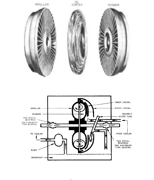
FIGURE 1 Power-transmitting elements of a hydrokinetic coupling (American Davidson)
FIGURE 2 Hydrokinetic coupling, scoop-trimming type (American Davidson)
where F represents energy, M is the mass of the working fluid, V is the velocity of the oil
particles before impingement, and V
2
is the velocity after impingement on the runner
blades.
This principle is used in traction units and, with modification, in torque converters.
Neither of these offers controlled variable speed.
In variable-speed units, the mass of the working fluid can be changed while the
machine is operating and infinitely variable output speed is achieved. Variation of oil
quantity can be accomplished in four ways: scoop-trimming couplings, leakoff couplings,
scoop-control couplings, and put-and-take couplings (Figures 2 to 5).
Components The following components are common to all the above types with few
exceptions.
The housing of the fluid drive serves four purposes
—
as a reservoir for the nonworking
oil, as a support for the bearings and scoop tube, as a guard to surround the moving parts,
and as a container for oil particles and vapors that prevents their escape to the atmos-
E
1
2
M1V
2
1
V
2
2
2
6.2.3 FLUID COUPLINGS 6.129
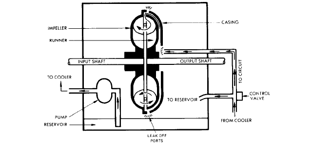
FIGURE 3 Hydrokinetic coupling, leakoff type (American Davidson)
phere. It also supports the oil pump when an internal pump is used. On small units, the
housing is of end-bell construction; all others are split on the horizontal centerline to facil-
itate inspection and maintenance.
Bearings are used to support the shafts radially and axially. In the case of smaller
industrial units, ball or roller bearings are usually used; larger machinery utilizes babbitt
radial bearings and Kingsbury thrust bearings. Input sleeve bearing pillow blocks often
support the internal oil pump driving and driven gears. In most cases, the thrust bearings
are designed to handle only the internal thrust of the fluid drive. Thrust developed by
sleeve bearing driving motors can be accepted by the hydraulic couplings, but driven
machines must usually have provisions to absorb their own thrust.
Shafts support the rotors and transmit driving torque to and from them. In some cases,
shafts are hollow and are used to supply oil to the bearings and to the working circuit (Fig-
ures 2 to 5).
Rotors are often compared to halves of grapefruit after the meat has been removed and
may be fabricated in three ways.The lightest-duty units are equipped with die-cast rotors
of SAE 356 aluminum. Heavier-duty units have rotors that are machined out of 4130 or
4340 aircraft-quality steel forgings.
Inner and outer casings are bowl-shaped members that bolt to the front of the impeller
to contain the oil in two connected areas known as the working circuit (Figure 2). One
chamber is formed by the impeller and inner casings. The other is formed between the
inner and outer casings and can be called the scoop-tube chamber. Ports in the inner cas-
ing permit oil to flow from one chamber to the other.
The scoop tube (Figure 2) can be moved radially or rotated inside the scoop tube cham-
ber and is supported by sleeve or antifriction bearings.The pickup end of the tube is between
the two casings facing the direction of oil rotation. Linkages permit the tube to be moved
from outside the housing, and seals prevent the leakage of oil or vapors at this penetration.
An oil pump is provided that may be an internally mounted gear pump driven from the
input shaft or an externally mounted positive displacement motor-driven pump. In cases
where extreme reliability is required, emergency standby ac- or dc-driven pumps may be
furnished. These pumps furnish light turbine oil to lubricate, transmit power, and remove
heat from the fluid drive. In many cases, they supply lubrication to the driver, the inter-
mediate gear boxes, and the driven machine.
Oil coolers are required on all drives rated above 3 hp (2.2 kw). These coolers remove
heat dissipated by the fluid drive and other machines for which they furnish lubrication.
Shell-and-tube water-to-oil exchangers are normally supplied, although finned-tube air-to-
oil exchangers are utilized where water is not available or economical. On pipeline work,
it is common to use in-line coolers. The product of the pipeline is put through one side of
the cooler to remove heat from the fluid-drive oil system.
6.130 CHAPTER SIX
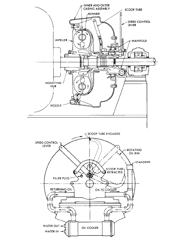
FIGURE 4 Hydrokinetic coupling, scoop-control type
Manifolds are usually used on scoop-controlled couplings in lieu of housings. They pro-
vide passages to permit oil flow to and from the working circuit and support the scoop tube
and, sometimes, one bearing on the output shaft.
Operation The flow of oil in the scoop-trimming fluid drive is begun by the circulating
pump, which is driven at constant speed by the input shaft, or external motor driver. The
circulating pump moves the oil from the reservoir at the bottom of the housing to an exter-
nal oil cooler (if used) and then to the rotating elements. Oil entering the rotating casing
is acted upon by centrifugal force caused by the casings rotating at the input speed. This
6.2.3 FLUID COUPLINGS 6.131
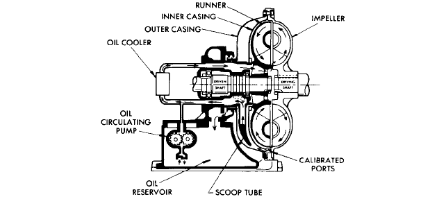
FIGURE 5 Hydrokinetic coupling, put-and-take type (American Davidson)
centrifugal force throws the oil outward against the side of the casing and into the impeller
and runner, or working circuit, where it takes the form of an annular ring. Communica-
tion ports in the inner casing permit the oil level to equalize in the two chambers.
The amount of oil in the working circuit is regulated by the scoop tube acting as a slid-
ing weir. The scoop tube removes the oil from the casing and empties it into the oil reser-
voir at the bottom of the housing, where it is ready to begin the cycle once more.
By either manual or automatic control, the scoop tube is moved in the casing. This, in
turn, sets the level of the oil is the working circuit because the oil tends to seek the same
level in the entire assembly. The scoop tube is designed to give fast response for both
increase and decrease of output speed as required. In the leakoff type of fluid drive (Fig-
ure 3), the scoop tube and outer casings are not used. Oil flow is initiated by a pump, usu-
ally of the viscous or centrifugal type, driven by the input shaft, through a heat exchanger
(if required) and to a two-way control valve. This control valve modulates between the two
extreme positions: all oil to the working circuit and all oil dumped back to the reservoir.
Oil in the working circuit is thrown out through orifices called leakoff ports. Flow is cre-
ated by centrifugal head, which varies with the depth of oil in the coupling.
If oil is added to the coupling faster than it is thrown out of the orifices, the quantity of
oil in the unit and the output speed increase. Obviously the converse is true as well, and
if oil is put into the working circuit at exactly the same rate that it is “leaked off,” the unit
runs at constant speed. This type of unit lends itself well to closed-loop automatic control,
which compensates for the differential flow through the leakoff ports. Manual control is
questionable because oil must be added at exactly the rate it is discharged or output speed
will drift.
In the scoop-control fluid drive, the communication ports in the inner casing are closed
to form orifices and the scoop tube casing is sealed at the shaft. This breaks the unit into
two separate chambers, the working circuit between the impeller and inner casing and the
rotating reservoir between the inner and outer casings.The two are connected only by the
orifices, or leakoff ports. Usually the housing, three bearings, and input shaft are omitted.
In this configuration, the input rotor and casings are supported by the driving motor. In
some cases, the mounting is accomplished through a solid hub as shown in Figure 4, and
in others through a disk capable of flexing to absorb slight misalignment. The runner and
output shaft are supported either by a pilot bearing and an outboard bearing or by a pilot
bearing and the driven machine through a piloted flexible coupling.
Oil flow is initiated by the scoop in the reservoir acting as a pump. This flow is
directed out through the manifold to the oil cooler, back to the manifold, and into the
working circuit.
A portion of the oil constantly flows through calibrated nozzles in the inner casing to
the outer casing, where it is held in an annular ring against the outer casing by centrifu-
gal force. The fluid drive is initially charged with just enough oil to fill the impeller and
6.132 CHAPTER SIX
FIGURE 6 Hydrodynamic coupling (American Davidson)
runner and the cooler circuit so the idle oil in the outer casing is a subtraction from the
working circuit. The movable scoop tube adjusts the oil quantity in the outer casing and
thus regulates the oil quantity in the working circuit. The scoop tube can be fully engaged,
where it skims off all the oil in the casing and thus fills the working circuit. Otherwise, it
can be retracted completely so all the oil lies idle in the outer casing and the unit is
“declutched.” Intermediate positions regulate torque and speed of the drive.
Put-and-take couplings (Figure 5) have not been manufactured in recent years. There
was, in the design of such couplings, a variation of the scoop control coupling wherein the
position of the scoop tube was fixed; thus, the tube provided circulation only between work-
ing circuit and cooler. The amount of oil in the coupling itself was regulated by a gear-type
pump that was operated in one direction to pump oil from a reservoir into a unit, stopped
to maintain constant coupling speed, or reversed to remove oil from the drive and pump it
into the reservoir. This created very unwieldy control systems having very poor response
characteristics with some bunting, and the design became obsolete.
Reversibility can be obtained by reversing the driving motor, provided that the unit
incorporates oil pumps that are not affected by input shaft rotations. In addition, units uti-
lizing scoop tubes must have dual tips that can accept the flow of oil from either side.
In all fluid drives, the same fluid is utilized to transmit power, to remove absorbed heat,
and to lubricate. Thus there is no requirement for internal seals, or slingers, and positive
lubrication is assured. Because the power-transmitting medium is the heat-absorbing
medium, there are no problems of heat transfer encountered in units utilizing oil pumps.
This type of unit can be selected with the capability of dissipating 100% or more of the
driving-motor rated power.
HYDRODYNAMIC DRIVES _____________________________________________
This type of fluid coupling is occasionally used to drive pumping equipment, usually in the
portable pump field (Figure 6).
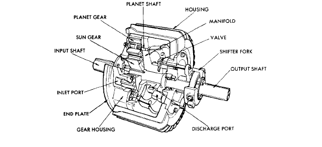
Basic Principle In the most common forms of hydrodynamic drives, planetary gear
trains utilize some components as oil pumps.Throttling the discharge of these pumps cre-
ates back pressure and increases drive torque.
Components The input shaft, supported by a bearing either on an independent bear-
ing pedestal or on a packaged subbase assembly, drives the housing, endplate, manifold,
and planetary gear shafts. These planet gears are partially surrounded by the manifold,
which forms a pump cavity. The sun gear drives the output shaft. The control yoke moves
the internal valve.
6.2.3 FLUID COUPLINGS 6.133
FIGURE 7 Hydroviscous coupling (American Davidson)
Operation When the driver is started, oil flow is initiated by planet gears rotating
against the sun gear. With the control yoke in the low-speed position, the mixing valve is
positioned to admit air mixed with oil, the pump discharge valve ports are wide open, and
the pump-developed head is approaching zero. The force on the pump gear teeth
approaches zero, and the output speed is minimum. As the control yoke is moved, the
pump discharge valves begin to close, less air is admitted, and the discharge pressure
rises. This develops resistance to pump rotation and imparts a force on the sun gear, and
the output shaft begins to rotate. If the oil discharge ports are closed, theoretically the
pump pressure will rise until the pump gear is locked to the sun gear. This would rotate
the output shaft at exactly input speed. In practice, leakage permits the pump to rotate
and the output shaft turns at a slightly lower speed than the input shaft. Reversibility
can be achieved simply by reversing the driving motor.
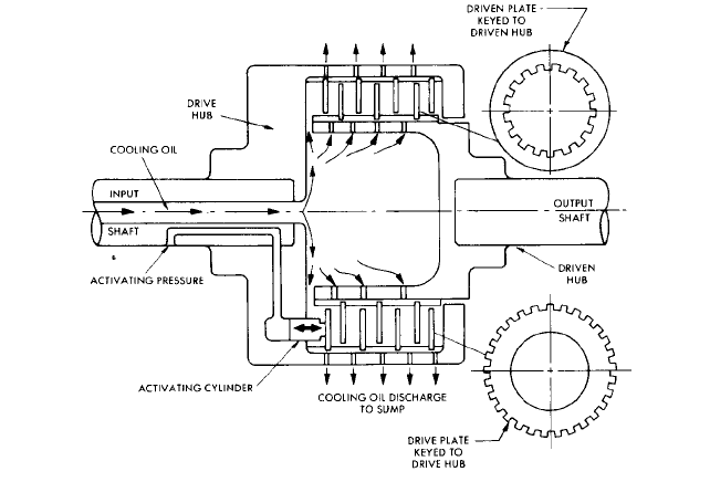
HYDROVISCOUS DRIVES______________________________________________
Hydroviscous drives are relatively new in commercial use. There are several manufactur-
ers in the United States who are marketing this type of drive for a wide range of pump
applications (Figure 7).
Basic Principle Hydroviscous drives operate on the basic principle that oil has viscos-
ity and energy is required to shear it. More energy is required to shear a thin film than
a thick one. The hydroviscous drive varies its torque capability by varying the film thick-
ness between driving and driven members.
Components The following components are common to all hydroviscous drives.The pri-
mary variations from one manufacturer to another are in the mechanics of control, the
numbers of disks, and the support of the rotors.
The housing serves the same purpose as in other fluid drives, supporting bearings,
guarding moving parts, and containing oil and vapors. In addition, one manufacturer uses
6.134 CHAPTER SIX
cored passages in the housing to introduce water to remove heat from the working fluid.
Bearings are usually of the antifriction type in small machines, with sleeve and Kingsbury
bearings available in large units. Shafts support rotors, transmit driving torque, and, in
most cases, are hollow to supply cooling oil and control oil.
The rotors have the driving hub keyed on the inside to driving disks and the driven hub
keyed at its inner diameter to the driven disks.
The disks are made of various materials and are usually grooved with some type of pat-
tern to direct cooling oil flow.
Pistons are hydraulic. When moved by control hydraulic oil, they force the disk stack
closer together.
Oil pumps are usually motor-driven, but sometimes are driven by the input shaft of the
coupling. It is not uncommon to have two separate pumping systems, one providing high-
pressure control oil and the other lower-pressure cooling oil.
Oil coolers are usually shell-and-tube water-to-oil heat exchangers, although air-to-
oil exchangers can be furnished and, as mentioned earlier, cored housings can sometimes
be used.
Operation Oil flow is initiated by the oil pumps, which force cooling oil through the disk
stack, draining into the sump. With the control set at minimum speed, the disks are at
maximum spacing and the coupling transmits minimum torque. As pressure is applied to
the piston, the disks are forced together. This decrease in film thickness between disks
increases the force transmitted from one plate to the next. At maximum piston pressure,
the spacing between plates is zero and the output shaft is driven at input shaft speed. In
the full-speed condition, this device is actually a lockup mechanical clutch; at reduced
speeds, it is an oil shear coupling; and in a narrow band between these two points of oper-
ation, it must be looked upon as an oil-cooled mechanical clutch. Reversibility can be
accomplished by reversing the driving motor if oil pumps are driven by separate motors.
HYDROSTATIC DRIVES________________________________________________
Basic Principle
There are many variations of hydrostatic variable-speed drives, but in
one form or another they invariably use positive displacement hydraulic pumps in con-
junction with positive displacement hydraulic motors.
In some cases, varying amounts of fluid are bypassed from the pump discharge back to
the pump suction. This provides a controllable variable flow to the positive displacement
motor and therefore a variable output speed. This system has no particular advantages
over the more common variable-speed drives. The higher-than-average first costs and
above-average maintenance required explain why this type of hydrostatic system is sel-
dom used.
In other cases, the hydrostatic drive system uses variable-flow positive displacement
pumps that may be of the sliding vane type or axial piston type (Figure 8). Reducing the
discharge flow on the hydraulic pump reduces output speed; increasing pump flow
increases output speed. This type of variable-speed drive is offered in package form with
pump, piping, and motor mounted in a common housing. It offers the capability of torque
multiplication, maintains a relatively constant efficiency regardless of speed, has excellent
control characteristics, and is widely used in the machine tool and other industries. The
output shaft can be reversed by valving (without changing motor rotation). This design
has inherently high first cost and maintenance requirements, precluding significant use
as a pump driver.
CAPACITY __________________________________________________________
Hydrokinetic Drive
Being centrifugal machines, fluid drives follow very familiar laws:
power varies as speed raised to the third power (Figure 9), as diameter to the second
power, and directly as the density of the working fluid.
6.2.3 FLUID COUPLINGS 6.135
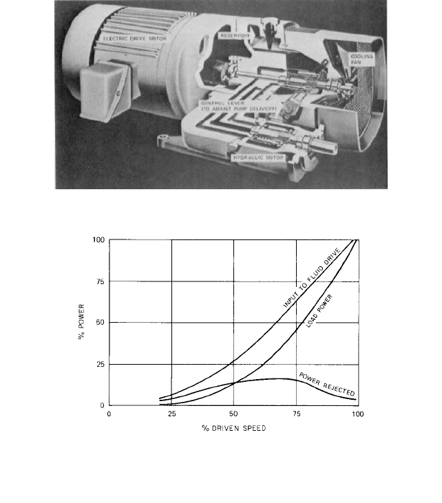
FIGURE 8 Typical package hydrostatic drive (Sperry Vickers)
FIGURE 9 Load power varies as speed cubed. This figure represents a pump operating in a system where all the
head is frictional, or where head varies as flow squared. In this system, the driven pump operates at only one point
on its characteristic curve, and therefore the shape of the pump curve is academic. Although the rapid loss of
hydraulic coupling efficiency at reduced speeds is quite obvious, the dramatic decrease in pump power
requirements results in a total system power that is most acceptable. Note that the heat rejection requirements
in the fluid drive are maximum at about 18% of the total load power.
Thus hydraulic capacity is governed by speed, diameter, and operating fluid; mechan-
ical capability is governed by the structural design of housing, bearings, shafts, rotors, and
casings; thermal capacity is limited by the capacity of the oil pumps, the specific heat and
thermal conductivity of the oil, and the ability of the heat exchanger to dissipate heat.
It should be noted that in scoop-trimming couplings, the oil pumps are usually sized
solely for heat dissipation. In the leakoff coupling, the orifices are sized to permit enough
oil flow to dissipate heat, and the pumps must handle this plus enough to fill the coupling
in a reasonable time. The scoop-control coupling has limited flow and pressure because
both are generated by the scoop tube. This may preclude its uses in certain positive dis-
placement pumping applications or where installation of coolers at a remote location is
required.
Hydrodynamic Drive This type of coupling varies so much in configuration that it is
impossible to establish similar laws. Because any given machine has a definable torque
limitation, we can state that power varies directly with speed.