Short T.A. Electric Power Distribution Handbook
Подождите немного. Документ загружается.


Transformers 215
where
V
kV
= rated line-to-line voltage, kV
f = frequency, Hz
C = capacitance from one phase to ground, mF
Normally, ferroresonance occurs without equipment failure if the crew
finishes the switching operation in a timely manner. The loud banging,
rumbling, and rattling of the transformer during ferroresonance may alarm
line crews. Occasionally, ferroresonance is severe enough to fail a trans-
former. The overvoltage stresses the transformer insulation, and the repeated
saturation may cause tank heating as flux leaves the core (although many
modes of ferroresonance barely saturate the transformer and do not cause
significant tank heating). Surge arresters are the most likely equipment casu-
alty. In attempting to limit the ferroresonant overvoltage, an arrester may
absorb more current than it can handle and thermally run away. Gapped
silicon-carbide arresters were particularly prone to failure, as the gap could
not reseal the repeated sparkovers from a long-duration overvoltage. Gapless
metal-oxide arresters are much more resistant to failure from ferroresonance
and help hold down the overvoltages. Ferroresonant overvoltages may also
fail customer’s equipment from high secondary voltages. Small end-use
arresters are particularly susceptible to damage.
Ferroresonance is more likely with
• Unloaded transformers — Ferroresonance disappears with load as
little as a few percent of the transformer rating.
• Higher primary voltages — Shorter cable lengths are required for
ferroresonance. Resonance is more likely even without cables, just
due to the internal capacitance of the transformer. With higher volt-
ages, the capacitances do not change significantly (cable capacitance
increases just slightly because of thicker insulation), but vars are
much higher for the same capacitance.
• Smaller transformers — Smaller no-load losses.
• Low-loss transformers — Smaller no-load losses.
Severe ferroresonance with voltages reaching peaks of 4 or 5 per unit
occurs on three-phase transformers with an ungrounded high-voltage wind-
ing during single-pole switching. If the transformer is fed by underground
cables and crews switch the transformer remotely, ferroresonance is likely.
On overhead circuits, ferroresonance is common with ungrounded primary
connections on 25- and 35-kV distribution systems. At these voltages, the
internal capacitance of most transformers is enough to ferroresonate. The use
of low-loss transformers has caused ferroresonance to appear on overhead
15-kV distribution systems as well. Amorphous core and low-loss silicon-
steel core transformers have much lower core losses than previous designs.
With less core losses, ferroresonance happens with lower amounts of capac-
1791_C04.fm Page 215 Thursday, August 7, 2003 11:18 AM
(C) 2004 by CRC Press LLC

216 Electric Power Distribution Handbook
itance. Tests by the Southern California Edison Company on three-phase
transformers with ungrounded primary connections found that ferroreso-
nance occurred when the capacitive power per phase exceeded the trans-
former’s no-load losses per phase by the following relationship (Jufer, 1994):
The phase-to-ground capacitance of overhead transformers is primarily
due to the capacitance between the primary and secondary windings (the
secondary windings are almost at zero potential). A typical 25-kVA trans-
former has a phase-to-ground capacitance of about 2 nF (Walling et al., 1995).
For a 7.2-kV line-to-ground voltage, 0.002 mF is 39 vars. So, if the no-load
losses are less than 39 vars/1.27 = 30.7 W per phase, the transformer may
ferroresonate under single-pole switching.
Normally, ferroresonance occurs on three-phase transformers, but ferrores-
onance can occur on single-phase transformers if they are connected phase to
phase, and one of the phases is opened either remotely or at the transformer.
Jufer (1994) found that small single-phase padmounted transformers con-
nected phase to phase ferroresonate when remotely switched with relatively
short cable lengths. Their tests of silicon-steel core transformers found that a
25-kVA transformer resonated with 50 ft (15 m) of 1/0 XLPE cable at 12 kV.
A 50-kVA transformer resonated with 100 ft of cable, and a 75-kVA unit
resonated with 150 ft of the cable. Peak primary voltages reached 3 to 4 per
unit. Secondary-side peaks were all under 2 per unit. Longer cables produced
slightly higher voltages during ferroresonance. Jufer found that ferroresonance
didn’t occur if the resistive load in watts per phase (including the transformer’s
no-load losses and the resistive load on the secondary) exceeded 1.15 times
the capacitive vars per phase (P
NL
+ P
L
> 1.15B
C
). Bohmann et al. (1991)
describes a feeder where single-phase loads were switched to a phase-to-phase
configuration, and the reconfiguration caused a higher-than-normal arrester
failure rate that was attributed to ferroresonant conditions on the circuit.
It is widely believed that a grounded-wye primary connection eliminates
ferroresonance. This is not true if the three-phase transformer has windings
on a common core. The most common underground three-phase distribution
transformer has a five-legged wound core. The common core couples the
phases. With the center phase energized and the outer phases open, the
coupling induces 50% voltage in the outer phases. Any load on the outer
two phases is effectively in series with the voltage induced on the center
phase. Because the coupling is indirect and the open phase capacitance is in
parallel with a transformer winding to ground, this type of ferroresonance
is not as severe as ferroresonance on configurations with an ungrounded
primary winding. Overvoltages rarely exceed 2.5 per unit.
Five-legged core ferroresonance also depends on the core losses of the
transformer and the phase-to-ground capacitance. If the capacitive vars
exceed the resistive load in watts, ferroresonance may occur. Higher capac-
BP
CNL
≥ 127.
1791_C04.fm Page 216 Thursday, August 7, 2003 11:18 AM
(C) 2004 by CRC Press LLC
Transformers 217
itances — longer cable lengths — generally cause higher voltages (see Figure
4.28). To limit peak voltages to below 1.25 per unit, the capacitive power
must be limited such that [equivalent to that proposed by Walling (1992)]:
with B
C
in vars and P
NL
in watts; both are per phase.
Ferroresonance can occur with five-legged core transformers, even when
switching at the transformer terminals, due to the transformer’s internal line-
to-ground capacitance. On 34.5-kV systems, transformers smaller than 500
kVA may ferroresonate if single-pole switched right at the transformer ter-
minals. Even on 15-kV class systems where crews can safely switch all but
the smallest 5-legged core transformers at the terminals, we should include
the transformer’s capacitance in any cable length calculation; the trans-
former’s capacitance is equivalent to several feet (meters) of cable. The
capacitance from line-to-ground is mainly due to the capacitance between
the small paper-filled layers of the high-voltage winding. This capacitance
is very difficult to measure since it is in parallel with the coil. Walling (1992)
derived an empirical equation to estimate the line-to-ground transformer
capacitance per phase in mF:
FIGURE 4.28
Five-legged core ferroresonance as a function of no-load losses and line-to-ground capacitance.
(Adapted from Walling, R. A., Barker, K. D., Compton, T. M., and Zimmerman, L. E., “Ferrores-
onant Overvoltages in Grounded Wye-Wye Padmount Transformers with Low-Loss Silicon
Steel Cores,” IEEE Trans. Power Delivery, 8(3), 1647-60, July 1993. With permission. ©1993 IEEE.)
0 5 10
1.0
1.5
2.0
2.5
Susceptance/Core loss (%/%)
Maximum overvoltage, per unit
BP
CNL
£ 186.
C
S
V
kVA
kV
=
0 000469
04
025
.
.
.
1791_C04.fm Page 217 Thursday, August 7, 2003 11:18 AM
(C) 2004 by CRC Press LLC

218 Electric Power Distribution Handbook
where
S
kVA
= transformer three-phase kVA rating
V
kV
= rated line-to-line voltage in kV
In vars, this is
where f is the system frequency, Hz.
To determine whether the transformer no-load losses exceed the capacitive
power, the transformer’s datasheet data is most accurate. For coming up
with generalized guidelines, using such data is not realistic since so many
different transformer makes and models are ordered. Walling (1992) offered
the following approximation between the three-phase transformer rating and
the no-load losses in watts per phase:
Walling (1992) used his approximations of transformer no-load losses and
transformer capacitance to find cable length criteria for remote single-pole
switching. Consider a 75-kVA 3-phase 5-legged core transformer at 12.47 kV.
Using these approximations, the no-load losses are 60.5 W per phase, and
the transformer’s capacitance is 27.4 vars per phase. To keep the voltage
under 1.25 per unit, the total vars allowed per phase is 1.85(60.5W) = 111.9
vars. So, the cable can add another 84.5 vars before we exceed the limit. At
12.47 kV, a 4/0 175-mil XLPE cable has a capacitance of 0.412 mF/mi, which
is 1.52 vars per foot. For this cable, 56 ft is the maximum length that we
should switch remotely. Beyond that, we may have ferroresonance above
1.25 per unit. Table 4.16 shows similar criteria for several three-phase trans-
formers and voltages. The table shows critical lengths for 4/0 cables; smaller
cables have less capacitance, so somewhat longer lengths are permissible.
At 34.5 kV, crews should only remotely switch larger banks.
Another situation that can cause ferroresonance is when a secondary has
ungrounded power factor correction capacitors. Resonance can even occur
on a grounded wye – grounded wye connection with three separate trans-
formers. With one phase open on the utility side, the ungrounded capacitor
bank forms a series resonance with the magnetizing reactance of the open
leg of the grounded-wye transformer.
Ferroresonance most commonly happens when switching an unloaded
transformer. It also usually happens with manual switching; ferroresonance
can occur because a fault clears a single-phase protective device, but this is
much less common. The main reason that ferroresonance is unlikely for most
situations using a single-phase protective device is that either the fault or
the existing load on the transformer prevents ferroresonance.
BfVS
C
kV kVA
= 0 000982
175 04
.
..
PS S
NL
kVA kVA
=-
()
()
454 113 3
10
..log
1791_C04.fm Page 218 Thursday, August 7, 2003 11:18 AM
(C) 2004 by CRC Press LLC

Transformers 219
If the fuse is a tap fuse and several customers are on a section, the trans-
formers will have somewhat different characteristics, which lowers the prob-
ability of ferroresonance (and ferroresonance is less likely with larger
transformers).
Solutions to ferroresonance include
• Using a higher-loss transformer
• Using a three-phase switching device instead of a single-phase
device
• Switching right at the transformer rather than at the riser pole
• Using a transformer connection not susceptible to ferroresonance
• Limiting remote switching of transformers to cases where the capac-
itive vars of the cable are less than the transformer’s no load losses
Arrester application on transformer connections susceptible to ferroreso-
nance brings up several interesting points. Ferroresonance can slowly heat
arresters until failure. Ferroresonance is a weak source; even though the per-
unit magnitudes are high, the voltage collapses when the arrester starts to
conduct (we cannot use the arresters time-overvoltage curve [TOV] to predict
failure). Normally, extended ferroresonance of several minutes can occur
before arresters are heated enough to enter thermal runaway. The most
vulnerable arresters are those that are tightly applied relative to the voltage
rating. Tests by the DSTAR group for ferroresonance on 5-legged core trans-
formers in a grounded wye – grounded wye connection (Lunsford, 1994;
Walling et al., 1994) found
TABLE 4.16
Cable Length Limits in Feet for Remote Single-Pole
Switching to Limit Ferroresonant Overvoltages to
Less than 1.25 per Unit
Transformer
Rating
kVA
Critical Cable Lengths, ft
12.47 kV
4/0 XLPE
175 mil
0.412 mF/mi
1.52 vars/ft
24.94 kV
4/0 XLPE
260 mil
0.261 mF/mi
4.52 vars/ft
34.5 kV
4/0 XLPE
345 mil
0.261 mF/mi
7.08 vars/ft
75 56 5 0
112.5 81 10 0
150 103 16 0
225 144 26 1
300 181 36 6
500 265 59 16
750 349 82 27
1000 417 100 36
1500 520 128 49
2000 592 146 56
1791_C04.fm Page 219 Thursday, August 7, 2003 11:18 AM
(C) 2004 by CRC Press LLC

220 Electric Power Distribution Handbook
• Arrester currents were always less than 2 A.
• Under-oil arresters, which have superior thermal characteristics,
reached thermal stability and did not fail.
• Porcelain-housed arresters showed slow heating — sometimes
enough to fail, sometimes not, depending on the transformer type,
cable lengths, and arrester type. Elbow arresters showed slow heat-
ing — slower than the riser-pole arresters. Failure times for either
type were typically longer than 30 min.
With normal switching times of less than one minute, arresters do not have
enough time to heat and fail. Crews should be able to safely switch trans-
formers under most circumstances. Load — even 5% of the transformer
rating — prevents ferroresonance in most cases. The most danger is with
unloaded transformers. If an arrester fails, the failure may not operate the
disconnect, which can lead to a dangerous scenario. When a line worker
recloses the switch, the stiff power-frequency source will fail the arrester.
The disconnect should operate and draw an arc. On occasion, the arrester
may violently shatter.
One option to limit the exposure of the arresters is to put the arresters
upstream of the switch. At a cable riser pole this is very difficult to do without
seriously compromising the lead length of the arrester.
4.10.3 Switching Floating Wye – Delta Banks
Floating wye – delta banks present special concerns. As well as being prone
to ferroresonance, single-pole switching can cause overvoltages due to a
neutral shift. On a floating wye – delta, the secondary delta connection fixes
the transformer’s primary neutral close to ground potential. After one phase
of the primary wye is opened, the neutral can float far from ground. This
causes overvoltages, both on the secondary side and the primary side. The
severity depends on the balance of the load.
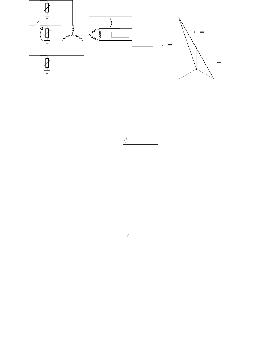
When crews open one of the power-leg phases, if there is no three-phase
load and only the single-phase load on the lighting leg of the transformer,
the open primary voltage V
open
reaches 2.65 times normal as shown in Figure
4.29. The voltage across the open switch also sees high voltage. The voltage
from B to B¢ in Figure 4.29 can reach over 2.75 per unit. Secondary line-to-
line voltages on the power legs can reach 1.73 per unit. The secondary delta
forces the sum of the three primary line-to-neutral voltages to be equal. With
single-phase load on phase C and no other load, the neutral shifts to the C-
phase voltage. The delta winding forces V
B¢N
to be equal to –V
AN
, which
significantly shifting the potential of point B¢.
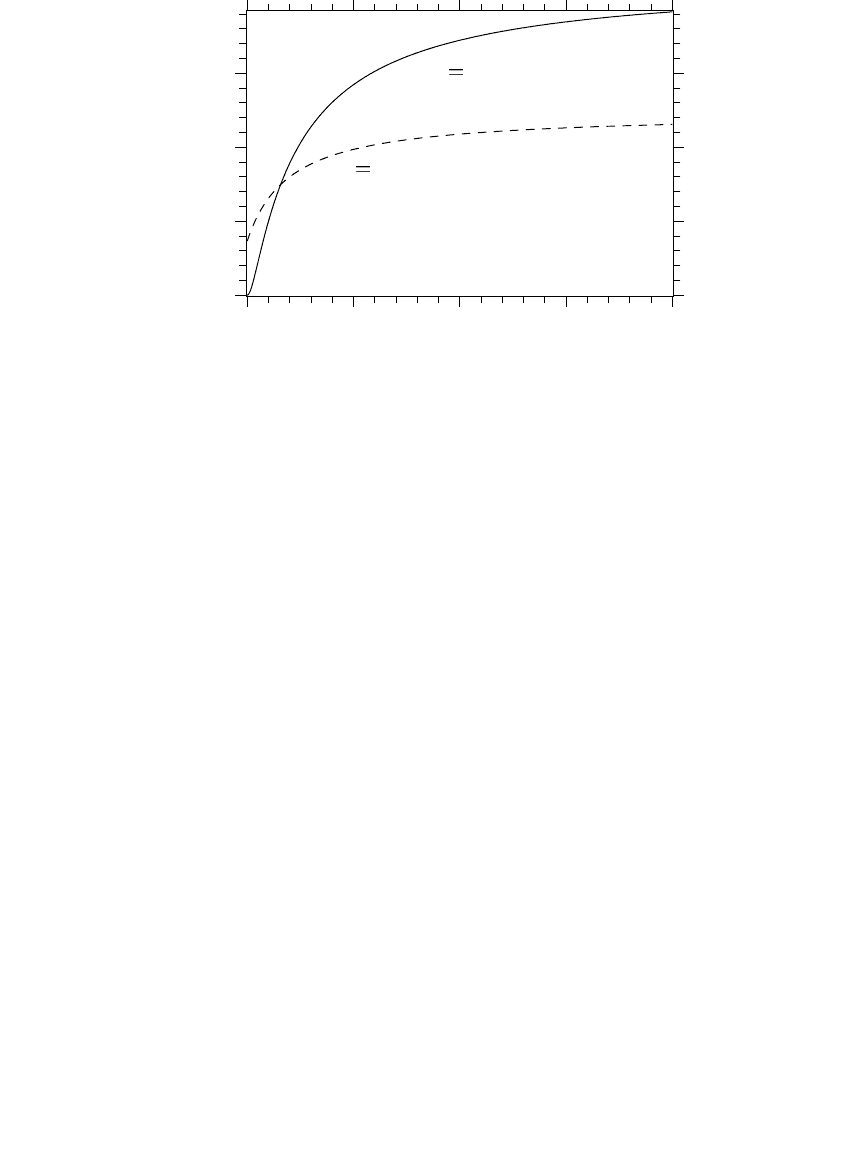
The line-to-ground voltage on the primary-side of the transformer on the
open phase is a function of the load unbalance on the secondary. Given the
ratio of the single-phase load to the three-phase load, this voltage is [assum-
1791_C04.fm Page 220 Thursday, August 7, 2003 11:18 AM
(C) 2004 by CRC Press LLC
Transformers 221
ing passive loads and that the power factor of the three-phase load equals
that of the single-phase load (Walling et al., 1995)]
where
On the secondary side, the worst of the two line-to-line voltages across
the power legs have the following overvoltages depending on loading bal-
ance (PTI, 1999):
Figure 4.30 shows these voltages as a function of the ratio K.
Contrary to a widespread belief, transformer saturation does not signifi-
cantly reduce the overvoltage. Walling et al.’s (1995) EMTP simulations
showed that saturation did not significantly reduce the peak voltage mag-
nitude. Saturation does distort the waveforms significantly and reduces the
energy into a primary arrester.
Some ways to avoid these problems are
• Use another connection — The best way to avoid problems with this
connection is to use some other connection. Some utilities do not
FIGURE 4.29
Neutral-shift overvoltages on a floating wye – delta transformer during single-pole switching.
1 phase
3-phase
balanced
load
Vectors for single-phase load
connected to the transformer
and no three-phase load
N = C
G
N
B’
C
A
AB
B’
G
B
V
open
V
s
V
B N
173%
V
B G
265%
V
AN
173%
V
KK
K
open
=
++
+
71
2
2
K =
Single-phase load
Balanced three-phase load
V
K
K
s
=
+
+
3
1
2
1791_C04.fm Page 221 Thursday, August 7, 2003 11:18 AM
(C) 2004 by CRC Press LLC
222 Electric Power Distribution Handbook
offer an open wye – delta connection and instead move customers
to grounded-wye connections.
• Neutral grounding — Ground the primary-wye neutral during
switching operations, either with a temporary grounding jumper or
install a cutout. This prevents the neutral-shift and ferroresonant
overvoltage. The ground-source effects during the short-time switch-
ing are not a problem. The line crew must remove the neutral jumper
after switching. Extended operation as a grounding bank can over-
heat the transformer and interfere with a circuit’s ground-fault pro-
tection schemes.
• Switching order — Neutral shifts (but not ferroresonance) are elimi-
nated by always switching in the lighting leg last and taking it out first.
Arrester placement is a sticky situation. If the arrester is upstream of the
switch, it does not see the neutral-shift/ferroresonant overvoltage. But the
transformer is not protected against the overvoltages. Arresters downstream
of the switch protect the transformer but may fail. One would rather have
an arrester failure than a transformer failure, unless the failure is near a line
crew (since an arrester is smaller, it is more likely than a transformer to
explode violently — especially porcelain-housed arresters). Another concern
was reported by Walling (2000): during switching operations, 10-per-unit
overvoltage bursts for 1/4 cycle ringing at about 2 kHz when closing in the
second phase. These were found in measurements during full-scale tests and
also in simulations. This transient repeats every cycle with a declining peak
magnitude for more than one second. If arresters are downstream from the
switches, they can easily control the overvoltage. But if they are upstream
of the switches, this high voltage stresses the transformer insulation.
FIGURE 4.30
Neutral-shift overvoltages as a function of the load unbalance.
0 5 10 15 20
0.5
1.0
1.5
2.0
Voltage, per unit
V
open
primary phase-to-ground
voltage on the open phase
V
s
secondary phase-to-phase voltage
K,ratio of single-phase load to three-phase load
1791_C04.fm Page 222 Thursday, August 7, 2003 11:18 AM
(C) 2004 by CRC Press LLC
Transformers 223
Overall, grounding the transformer’s primary neutral is the safest
approach.
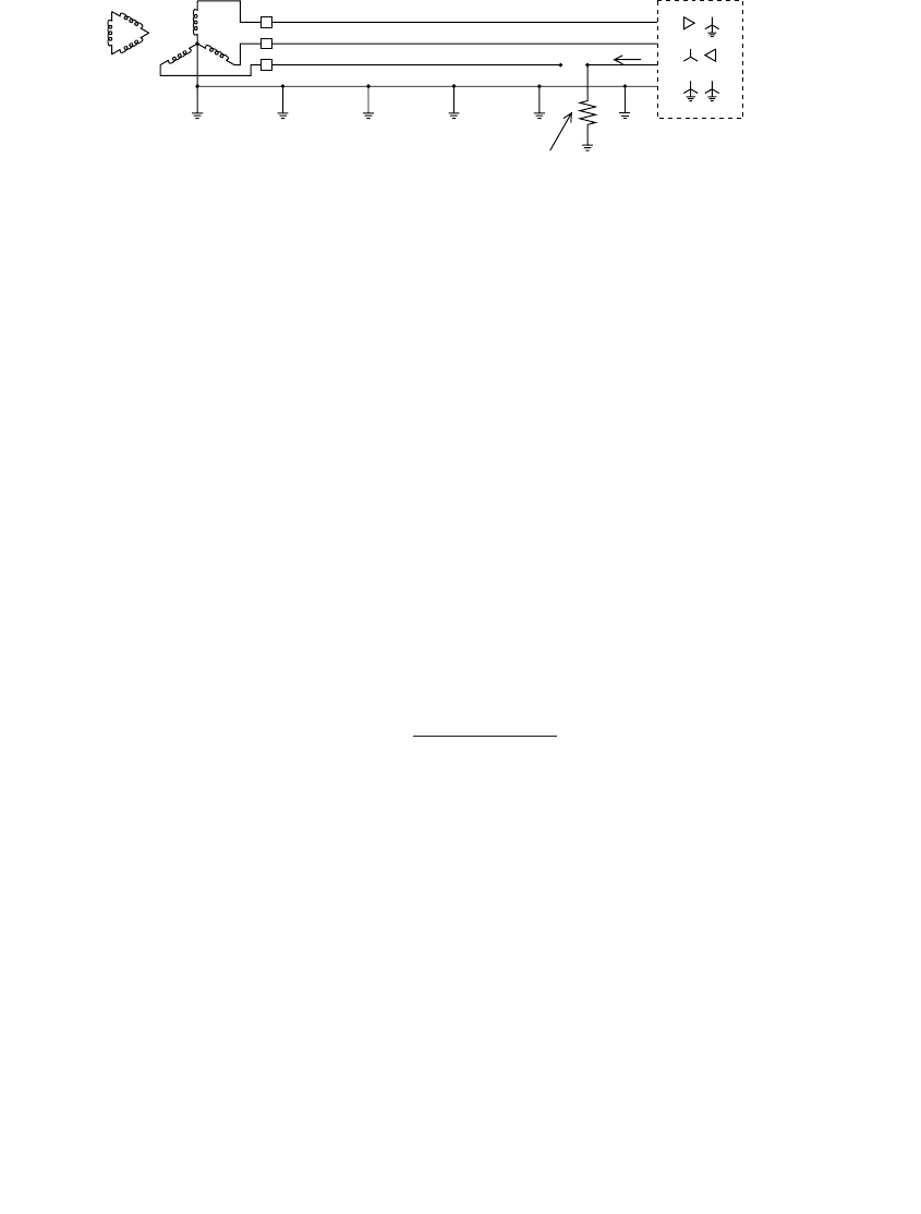
4.10.4 Backfeeds
During a line-to-ground fault where a single-phase device opens, current may
backfeed through a three-phase load (see Figure 4.31). It is a common mis-
conception that this type of backfeed can only happen with an ungrounded
transformer connection. Backfeed can also occur with a grounded three-phase
connection. This creates hazards to the public in downed wire situations.
Even though it is a weak source, the backfed voltage is just as dangerous.
Lineworkers also have to be careful. A few have been killed after touching
wires downstream of open cutouts that they thought were deenergized.
The general equations for the backfeed voltage and current based on the
sequence impedances of the load (Smith, 1994) are
where
A =
Z
1
= positive-sequence impedance of the load, W
Z
2
= negative-sequence impedance of the load, W
Z
0
= zero-sequence impedance of the load, W
R
F
= fault resistance, W
V = line-to-neutral voltage, V
The line and source impedances are left out of the equations because they
are small relative to the load impedances. Under an open circuit with no
fault (R
F
= •), the backfeed voltage is
FIGURE 4.31
Backfeed to a downed conductor.
Three-phase transformer(s)
with any of the
connections shown
R
F
distribution
substation
broken conductor
with the load side down
I
AZZV
ZZZ RA
F
F
=
-
()
+
3
3
02
012
VRI
FFF
=
ZZ ZZ ZZ
01 12 02
++
1791_C04.fm Page 223 Thursday, August 7, 2003 11:18 AM
(C) 2004 by CRC Press LLC

224 Electric Power Distribution Handbook
For an ungrounded transformer connection (Z
0
= •), the backfeed current is
The backfeed differs depending on the transformer connection and the
load:
•Grounded wye – grounded wye transformer connection
•Will not backfeed the fault when the transformer is unloaded or
has balanced line-to-ground loads (no motors). It will backfeed
the fault with line-to-line connected load (especially motors).
• Ungrounded primary transformer
•Will backfeed the fault under no load. It may not be able to
provide much current with no load, but there can be significant
voltage on the conductor. Motor load will increase the backfeed
current available.
Whether it is a grounded or ungrounded transformer, the available back-
feed current depends primarily on the connected motor load. Motors dom-
inate since they have much lower negative-sequence impedance; typically
it is equal to the locked-rotor impedance or about 15 to 20%. With no fault
impedance (R
F
= 0), the backfeed current is approximately:
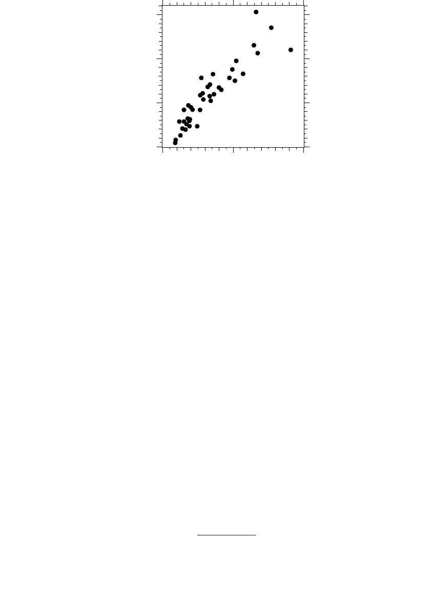
where M
kVA
is the three-phase motor power rating in kVA (and we can make
the common assumption that 1 hp = 1 kVA), V
LG,kV
is the line-to-ground
voltage in kV, and Z
2,pu
is the per-unit negative-sequence (or locked-rotor)
impedance of the motor(s). Figure 4.32 shows the variation in backfeed
current versus motor kVA on the transformer for a 12.47-kV system (assum-
ing Z
2,pu
= 0.15).
The voltage on the open phases depends on the type of transformer con-
nection and the portion of the load that is motors. Figure 4.33 shows the
backfeed voltage for an open circuit and for a typical high-impedance fault
(R
F
= 200 W).
As discussed in Chapter 7, the maximum sustainable arc length in inches
is roughly where I is the rms current in amperes, and V is the
V
AZZV
A
F
=
-
()
3
02
I
ZZV
ZZ R Z Z
F
F
=
-
()
++
()
12
12 1 2
2
3
I
M
VZ
F
kVA
LG kV
pu
=
◊9
2
,
,
lIV=◊
1791_C04.fm Page 224 Thursday, August 7, 2003 11:18 AM
(C) 2004 by CRC Press LLC