Short T.A. Electric Power Distribution Handbook
Подождите немного. Документ загружается.

Voltage Regulation
245
5.4 Regulators
Voltage regulators are autotransformers with automatically adjusting taps.
Commonly, regulators provide a range from –10 to +10% with 32 steps. Each
step is 5/8%, which is 0.75 V on a 120-V scale.
A single-phase regulator has three bushings: the source (S), the load (L),
and the source-load (SL). The series winding is between S and L. Figure 5.2
shows a straight regulator (ANSI type A) with the taps on the load side. An
ANSI type B, the inverted design, has the taps on the source bushing. The
regulator controller measures current with a CT at the L bushing and mea-
sures the voltage with a PT between L and SL. Regulators have a reversing
switch that can flip the series winding around to change back and forth
between the boost and the buck connection.
Regulators are rated on current (IEEE Std. C57.15-1999). Regulators also
have a kVA rating which is the two-winding transformer rating and not the
load-carrying capability. A regulator at 7.62 kV line to ground with a
±
10%
range and a load current rating of 100 A has a kVA rating of 0.1(7.62
kV)(100A) = 76 kVA. The load-carrying capability is ten times the regulator’s
kVA rating.
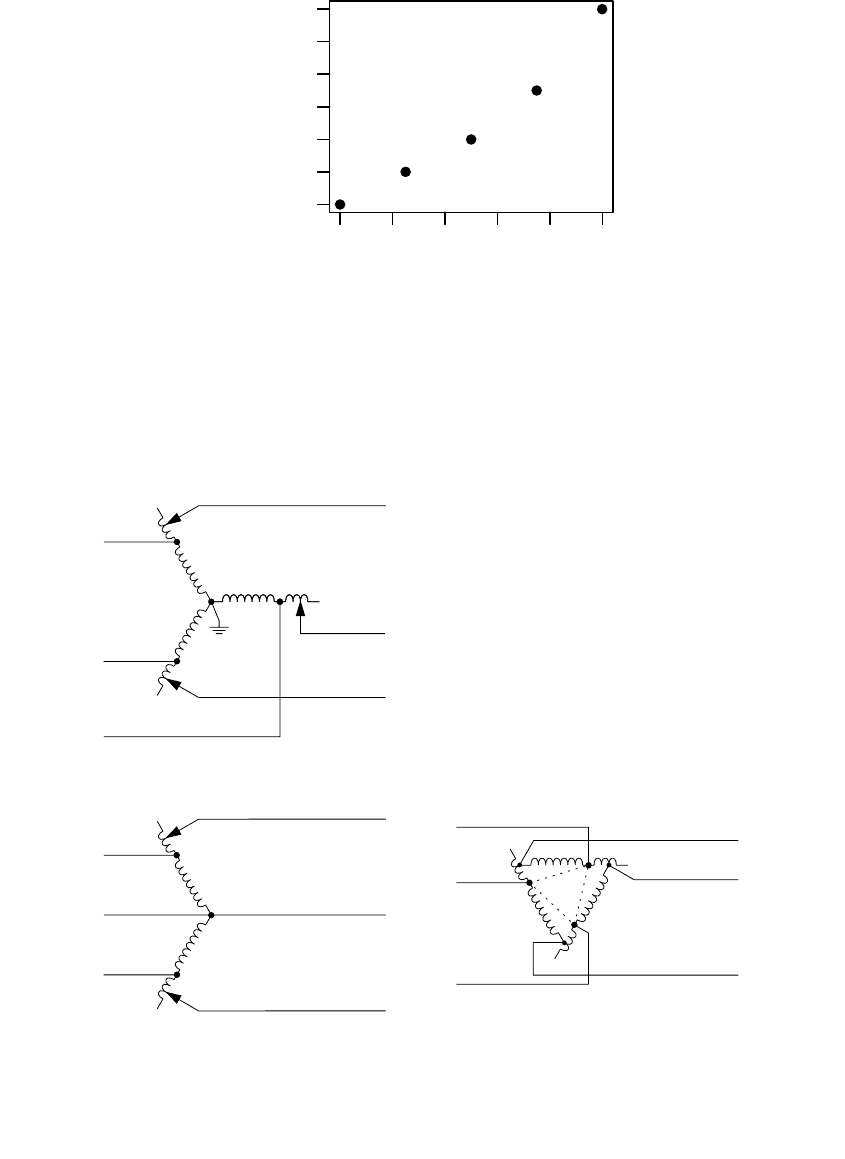
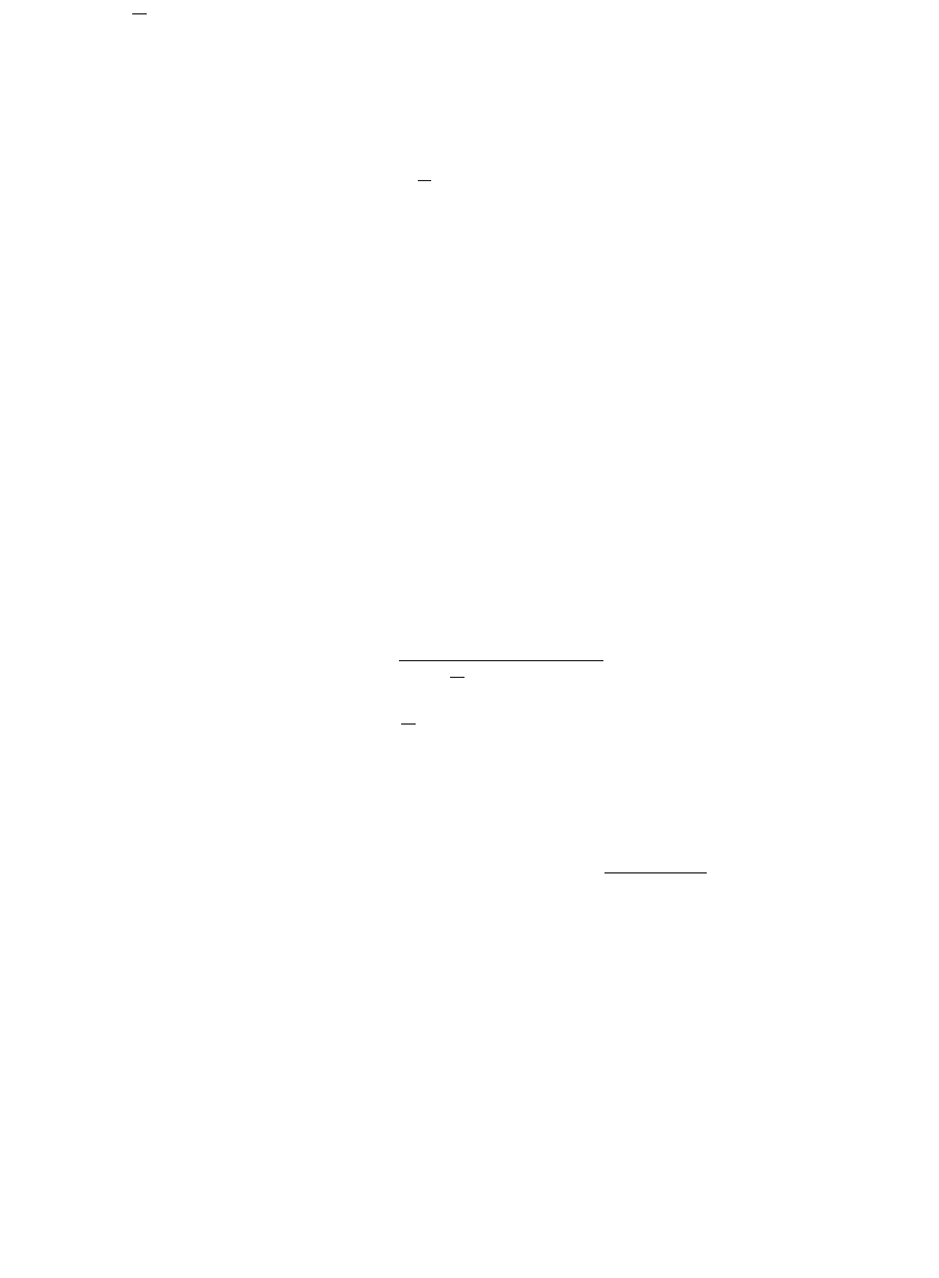
By reducing the range of regulation, we can extend the rating of the
regulator. Reducing the range from
±
10 to
±
5% increases the rating by 60%
(see Figure 5.3).
The impedance is the two-winding impedance times a base value about
ten times as large. Because the impedance is so small, we can normally
neglect it.
Three-phase regulators, often used in stations, are used on wye or delta
systems. A three-phase regulator controls all three phases simultaneously.
These are normally larger units. The normal connection internally is a wye
connection with the neutral point floating.
Commonly, utilities use single-phase units, even for regulating three-phase
circuits. We can connect single-phase regulators in several ways [see Figure
5.4 and (Bishop et al., 1996)]:
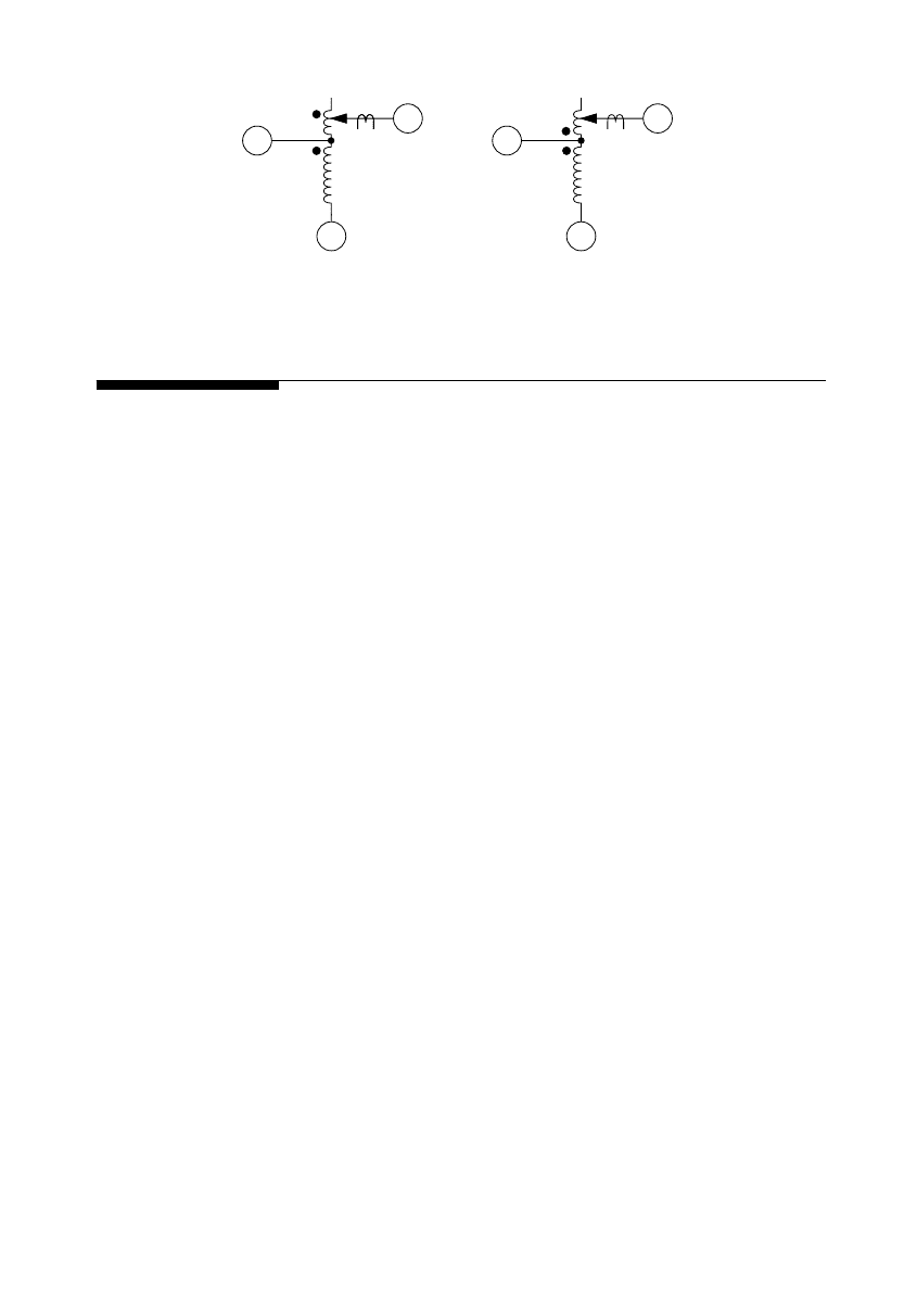
FIGURE 5.2
ANSI type A single-phase regulator, meaning taps on the load bushing.
Boost connection
S
L
SL
Buck connection
S
L
SL
1791_book.fm Page 245 Monday, August 4, 2003 3:20 PM
(C) 2004 by CRC Press LLC
246
Electric Power Distribution Handbook
FIGURE 5.3
Increased regulator ratings with reduced regulation range.
FIGURE 5.4
Three-phase regulator connections.
Percent regulation range (+/–)
Rating, percent of nameplate
10 98765
100 120 140 160
Grounded-wye connection
Open-delta connection Closed-delta (leading) connection
lagging unit
leading unit
1791_book.fm Page 246 Monday, August 4, 2003 3:20 PM
(C) 2004 by CRC Press LLC
Voltage Regulation 247
• Line to neutral — On four-wire systems, three-phase circuits normally
have three single-phase regulators connected line to neutral. Line-
to-neutral connections are also appropriate for single-phase and two-
phase circuits. Each regulator independently controls voltage, which
helps control voltage unbalance as well as steady-state voltage.
• Open delta — Only two single-phase regulators are needed, each
connected phase to phase.
• Closed delta — Three regulators are connected phase to phase. Using
the closed delta extends the regulation range by 50%, from ±10 to
±15%.
In both of the delta connections, the regulators see a current phase-shifted
relative to the voltage. In the leading connection with unity power factor
loads, the line current through the regulator leads the line-to-line voltage by
30∞. The lagging connection has the current reversed: for a unit power factor
load, the line current lags the line-to-line voltage by 30∞. In the open-delta
configuration, one of the units is leading and the other is lagging. In the
closed-delta arrangement, all three units are either leading or all three are
lagging. Although uncommon, both of the delta connections can be applied
on four-wire systems.
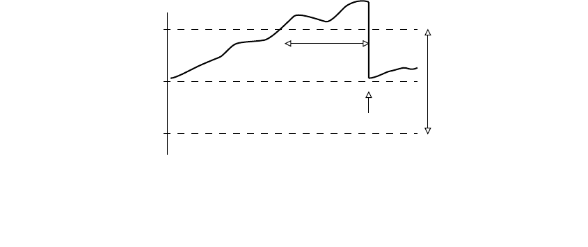
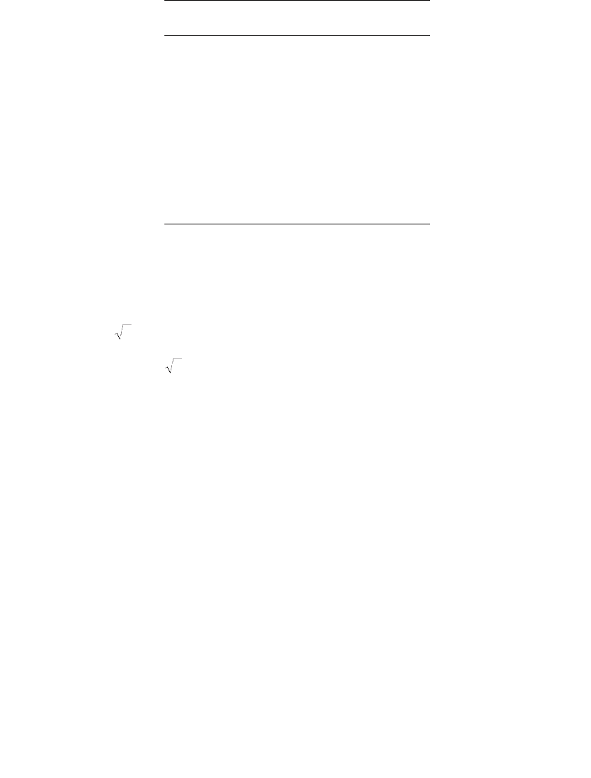
Regulators have a voltage regulating relay that controls tap changes. This
relay has three basic settings that control tap changes (see Figure 5.5):
• Set voltage — Also called the set point or bandcenter, the set voltage
is the desired output of the regulator.
• Bandwidth — Voltage regulator controls monitor the difference
between the measured voltage and the set voltage. Only when the
difference exceeds one half of the bandwidth will a tap change start.
Use a bandwidth of at least two times the step size, 1.5 V for ±10%,
32-step regulators. Settings of 2 and 2.5 V are common.
• Time delay — This is the waiting time between the time when the
voltage goes out of band and when the controller initiates a tap
FIGURE 5.5
Regulator tap controls based on the set voltage, bandwidth, and time delay.
BandwidthSet voltage
Time delay
Tap change
1791_book.fm Page 247 Monday, August 4, 2003 3:20 PM
(C) 2004 by CRC Press LLC

248 Electric Power Distribution Handbook
change. Longer time delays reduce the number of tap changes. Typ-
ical time delays are 30 to 60 sec.
If the voltage is still out of bounds after a tap change, the controller makes
additional tap changes until the voltage is brought within bounds. The exact
details vary by controller, and some provide programmable modes. In some
modes, controllers make one tap change at a time. In other modes, the
controller may initiate the number of tap changes it estimates are needed to
bring the voltage back within bounds. The time delay relay resets if the
voltage is within bounds for a certain amount of time.
A larger bandwidth reduces the number of tap changes, but at a cost. With
larger bandwidth, the circuit is not as tightly regulated. We should include
the bandwidth in voltage profile calculations to ensure that customers are
not given over or under voltages. Voltage that was used for bandwidth can
be used for voltage drop along the circuit. With a higher bandwidth we may
need more regulators on a given line. So, use at least two times the step size,
but do not use excessively high bandwidths such as 3 or 3.5 V.
In addition to these basics, regulator controllers also have line-drop com-
pensation to boost voltages more during heavy load. Controllers also may
have high and low voltage limits to prevent regulation outside of a desired
range of voltages. In addition to the regulator and control application infor-
mation provided here, see Beckwith (1998), Cooper Power Systems (1978),
General Electric (1979), and Westinghouse (1965).
Many regulators are bi-directional units; they can regulate in either direc-
tion, depending on the direction of power flow. A bi-directional regulator
measures voltage on the source side using an extra PT or derives an estimate
from the current. If the regulator senses reverse power flow, it switches to
regulating the side that is normally the source side. We need reverse mode
for a regulator on circuits that could be fed by an alternate source in the
reverse direction. Without a reverse mode, the regulator can cause voltage
problems during backfeeds. If a unidirectional regulator is fed “backwards,”
the regulator PT is now on the side of the source. Now, if the voltage drops,
the regulator initiates a tap raise. However, the voltage the PT sees does not
change because it is on the source side (very stiff). What happened was the
voltage on the load side went down (but the regulator controller does not
know that because it is not measuring that side). The controller still sees
low voltage, so it initiates another tap raise which again lowers the voltage
on the other side of the regulator. The controller keeps trying to raise the
voltage until it reaches the end of its regulation range. So, we have an already
low voltage that got dropped by an extra 10% by the unidirectional regulator.
If the controller initially sees a voltage above its set voltage, it ratchets all
the way to the high end causing a 10% overvoltage. Also, if the incoming
voltage varies above and below the bandwidth, the regulator can run back
and forth between extremes. A bi-directional regulator prevents these run-
aways. Depending on its mode, under reverse power, a bi-directional reg-
ulator can regulate in the reverse direction, halt tap changes, or move to the
1791_book.fm Page 248 Monday, August 4, 2003 3:20 PM
(C) 2004 by CRC Press LLC
Voltage Regulation 249
neutral point (these last two do not require PTs on both sides but just power
direction sensing).
Regulators also have an operations counter. The counter helps identify
when a regulator is due for refurbishment. Regulators are designed to per-
form many tap changes, often over one million tap changes over the life of
a regulator. A regulator might change taps 70 times per day, which is 25,000
times per year (Sen and Larson, 1994). A regulator counter also provides a
good warning indicator; excessive operations suggest that something is
wrong, such as wrong line drop compensation settings, a bandwidth or time
delay that is too small, or widely fluctuating primary voltages.
Regulators have “drag hands” — markers on the tap position indicator
that show the maximum and minimum tap positions since the drag hands
were last reset. The drag hands are good indicators of voltage problems. If
maintenance reviews continually show the drag upper hand pegging out at
+10%, the upstream voltage is probably too low. More work is needed to
correct the circuit’s voltage profile. Advanced controllers record much more
information, including tap change records and demand metering to profile
voltages, currents, and power factors.
5.4.1 Line-Drop Compensation
LTC transformer and regulator controls can be augmented with line-drop
compensation. During heavy load, the controller boosts voltage the most,
and during light load, voltage is boosted the least. The line-drop compen-
sator uses an internal model of the impedance of the distribution line to
match the line impedance. The user can set the R and X values in the
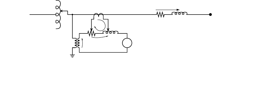
compensator to adjust the compensation. The controller adjusts taps based
on the voltage at the voltage regulating relay, which is the PT voltage plus
the voltage across the line-drop compensator circuit (see Figure 5.6). With
no compensation, the voltage regulating relay adjusts the taps based on the
PT voltage.
Since load on a typical distribution line is distributed, R and X compen-
sator settings are chosen so that the maximum desired boost is obtained
FIGURE 5.6
Line drop compensator circuit.
PT
CT Regulation point
Voltage
Regulating
Relay
R
X
RX
I
I/ct
V/pt
(R+jX)(I/ct)
1791_book.fm Page 249 Monday, August 4, 2003 3:20 PM
(C) 2004 by CRC Press LLC

250 Electric Power Distribution Handbook
under heavy load while a given voltage is obtained under light load. There
are two main approaches for selecting settings:
• Load center — The settings are chosen to regulate the voltage at a
given point downstream of the regulator.
• Voltage spread — The R and X settings are chosen to keep the voltage
within a chosen band when operating from light load to full load.
The R and X settings may or may not be proportional to the line’s
R and X.
The main complication of all of the methods is that the load and power
factors change (especially with downstream capacitor banks). Many regula-
tors are set up without line drop compensation. It is obviously easier and
less prone to mistakes, but we are losing out on some significant capability.
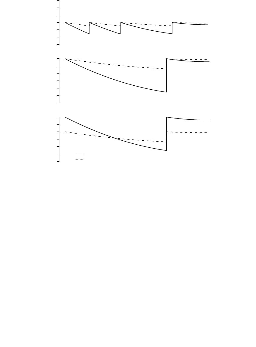
If we set the regulator set voltage at 120 V, and we do not get enough boost
along the line, we will need more regulators. With a higher set voltage such
as 126 V, we do not need as many regulators, but we have high voltages at
light load and possibly overvoltages if the circuit has capacitors. With line
drop compensation, we have boost when we need it during heavy load, but
not during light load (see Figure 5.7). Line-drop compensation also normally
leads to a smaller range of fluctuations in voltage through the day for
customers along the circuit.
5.4.1.1 Load-Center Compensation
The classic way to set compensator settings is to use the load-center method.
Consider a line with impedances R
L
and X
L
with a load at the end. Now, if
we pick the R
set
and X
set
of the compensator to match those of the line, as
the load changes the regulator responds and adjusts the regulator taps to
keep the voltage constant, not at the regulator but at the load. To achieve
this, we can set the R
set
and X
set
of the regulator as
where
R
set
= regulator setting for resistive compensation, V
X
set
= regulator setting for reactive compensation, V
I
CT
= primary rating of the current transformer, A
N
PT
= potential transformer ratio (primary voltage/secondary voltage)
R
L
= primary line resistance from the regulator to the regulation point, W
X
L
= primary line reactance from the regulator to the regulation point, W
R
I
N
R
X
I
N
X
set
CT
PT
L
set
CT
PT
L
=
=
1791_book.fm Page 250 Monday, August 4, 2003 3:20 PM
(C) 2004 by CRC Press LLC
Voltage Regulation 251
A regulator’s R and X compensator settings are in units of volts. By using
volts as units, we can directly see the impact of the regulator on a 120-V
scale. Consider an example where the set voltage is 120 V. With a current at
unity power factor and R
set
= 6 V (X
set
does not matter at unity power factor),
the controller regulates the voltage to 120 + 6 = 126 V when the current is
at the peak CT rating. If the current is at half of the CT rating, the controller
regulates to the set voltage plus 3 or 123 V. Available compensator settings
are normally from –24 to +24 V.
Note that the primary CT rating is an important part of the conversion to
compensator settings. The CT rating may be the same as the regulator rating
or it may be higher. The CT rating is given on the nameplate. Table 5.6 shows
the regulator ratings and primary CT current rating for one manufacturer.
Regulators may be applied where the nameplate voltage does not match the
system voltage if they are close enough to still allow the desired regulation
range at the given location. Also, some regulators have taps that allow them
to be used at several voltages. Make sure to use the appropriate PT ratio for
the tap setting selected.
FIGURE 5.7
Voltage profiles on a circuit with various forms of regulation.
Vset=120 V, No line drop compensation
114 118 122 126
Vset=126 V, No line drop compensation
Voltage
114 118 122 126
Line drop compensation
Source End
114 118 122 126
Full load
Light load
1791_book.fm Page 251 Monday, August 4, 2003 3:20 PM
(C) 2004 by CRC Press LLC
252 Electric Power Distribution Handbook
When specifying impedances for the line-drop compensator, use the cor-
rect line impedances. For a three-phase circuit, use the positive-sequence
impedance. For a single-phase line, use the loop impedance Z
S
which is
about twice the positive-sequence impedance.
On a delta regulator, either an open delta or a closed delta, divide the PT
ratio by . On a delta regulator the PT connects from phase to phase, but
the internal circuit model of the line-drop compensator is phase to ground,
so we need the factor to correct the voltage.
Line-drop compensation works perfectly for one load at the end of a line,
but how do we set it for loads distributed along a line? If loads are uniformly
distributed along a circuit that has uniform impedance, we can hold the
voltage constant at the midpoint of the section by using:
• 3/8 rule — For a uniformly distributed load, a regulator can hold
the voltage constant at the midpoint of the circuit if we use line-drop
compensation settings based on 3/8 of the total line impedance. A
circuit with a uniformly distributed load has a voltage drop to the
end of the circuit of one half of the drop had all of the loads been
lumped into one load at the end of the circuit. Three-fourths of this
drop is on the first half of the circuit, so (1/2)(3/4) = 3/8 is the
equivalent voltage drop on a uniformly distributed load.
Make sure not to allow excessive voltages. We can only safely compensate
a certain amount, and we will have overvoltages just downstream of the
regulator if we compensate too much. Check the voltage to the voltage
regulating relay to ensure that it is not over limits. The maximum voltage is
V
max
= V
set
+ (pf ◊R
set
+ qf ◊X
set
) I
max
TABLE 5.6
Regulator and Primary CT Ratings in Amperes
Regulator Current
Ratings
CT
Primary Current
25 25
50 50
75 75
100 100
150 150
167, 200 200
219, 231, 250 250
289, 300 300
328, 334, 347, 400 400
418, 438, 463, 500 500
548, 578, 656, 668 600
833, 875, 1000, 1093 1000
1332, 1665 1600
3
3
1791_book.fm Page 252 Monday, August 4, 2003 3:20 PM
(C) 2004 by CRC Press LLC

Voltage Regulation 253
where
V
set
= regulator set voltage
R
set
= resistive setting for compensation, V
X
set
= reactive setting for compensation, V
pf = load power factor
qf = load reactive power factor = sin(cos
–1
(pf))
I
max
= maximum load current in per unit relative to the regulator CT rating
If V is more than what you desired, reduce R
set
and X
set
appropriately to meet
your desired limit.
5.4.1.2 Voltage-Spread Compensation
In another method, the voltage-spread method, we find compensator settings
by specifying the band over which the load-side voltage should operate. For
example, we might want the regulator to regulate to 122 V at light load and
126 V at full load. If we know or can estimate the light-load and full-load
current, we can find R and X compensator settings to keep the regulated
voltage within the proper range. If we want the regulator to operate over a
given compensation range C, we can choose settings to satisfy the following:
C = V – V
set
= pf ◊R
set
+ qf ◊X
set
where
R
set
= resistive setting for compensation, V
X
set
= reactive setting for compensation, V
pf = load power factor
qf = load reactive power factor = sin(cos
–1
(pf))
C = total desired compensation voltage, V
V
set
= regulator set voltage, V
V = voltage that the controller will try to adjust the regulator to, V
With line current operating to the regulator CT rating limit (which is often
the regulator size) and the current at the given power factor, these settings
will boost the regulator by C volts on a 120-V scale. Any number of settings
for R
set
and X
set
are possible to satisfy this equation. If we take
where the X/R ratio is selectable, the settings are
XR
set
X
R
set
=
R
C
pf qf
X
C
pf qf
R
set
X
R
set
X
R
X
R
X
R
set
=
+
=
+
=
1791_book.fm Page 253 Monday, August 4, 2003 3:20 PM
(C) 2004 by CRC Press LLC
254 Electric Power Distribution Handbook
where
= X/R ratio of the compensator settings
Note that C must be given as seen on the regulator PT secondaries, on a
120-V base. As an example, if the feeder voltage should be not more than
126 V at the limit of the regulator, and the desired voltage at no load is 122 V,
set the regulator set voltage at 122 V and find R
set
and X
set
to give C = 4 V.
For a power factor of 0.85 and = 3, the equations above give R
set
= 1.64
V and X
set
= 4.94 V.
To control the voltage range for a light load other than zero and for a peak
load other than the regulator CT rating, we can use the following to find the
voltage swing from light load to full load as
V
max
– V
min
= (pf ◊R
set
+ qf ◊X
set
)I
max
– (pf ◊R
set
+ qf ◊X
set
)I
min
where
V
max
= desired voltage at the maximum load current on a 120-V base, V
V
min
= desired voltage at the minimum load current on a 120-V base, V
I
max
= maximum load current in per-unit relative to the regulator CT rating
I
min
= minimum load current in per-unit relative to the regulator CT rating
Now, the R and X settings are
And, the regulator set voltage is
With a compensator X/R ratio equal to the line X/R ratio, these equations
move the effective load center based on the choice of voltage and current
minimums and maximums.
Just like we can choose to have the compensator X/R ratio equal the line
X/R ratio, we can choose other values as well. There are good reasons why
we might want to use other ratios; this is done mainly to reduce the sensi-
tivity to power factor changes. The zero reactance method of selecting com-
pensator makes X
set
= 0 (and the compensator X/R = 0) but otherwise uses
the same equations as the voltage spread method (General Electric, 1979).
X
R
X
R
R
V
pf qf I I
XR
set
X
R
set
X
R
set
=
-
+-
=
max min
max min
V
()( )
VV pfRqfX I
set set set
=-◊+◊ =-
-
-
min min min
max min
max min
min
V
VV
II
I()
1791_book.fm Page 254 Monday, August 4, 2003 3:20 PM
(C) 2004 by CRC Press LLC