Short T.A. Electric Power Distribution Handbook
Подождите немного. Документ загружается.


Voltage Regulation 255
By making X
set
zero, the compensator is not sensitive to variations in power
factor caused by switched capacitors or load variation; only real power
changes cause regulator movement. This method also simplifies application
of regulators. The equations become
And, the regulator set voltage is
V
set
= V
min
– (pf ◊R
set
)I
min
The equations simplify more if we assume that I
min
= 0 (our error with this
is that voltages run on the high side during light load). A further simplifi-
cation is to assume that the power factor is one. If the power factor is less
than that at full load, the regulator will not boost the voltage quite as much.
Often, we do not know the power factor at the regulator location anyway.
This method is useful with switched capacitor banks close to the regulator.
It does not perform well for low power factors if we have assumed a power
factor near unity. With this control, the regulator will not provide enough
boost with poor power-factor load.
Another option is to take X/R = 0.6, which weights the real power flow
more than the reactive power flow, but not as extremely as the zero reactance
compensation method. So, although the controller is somewhat desensitized
to changes in power factor, the regulator provides some action based on
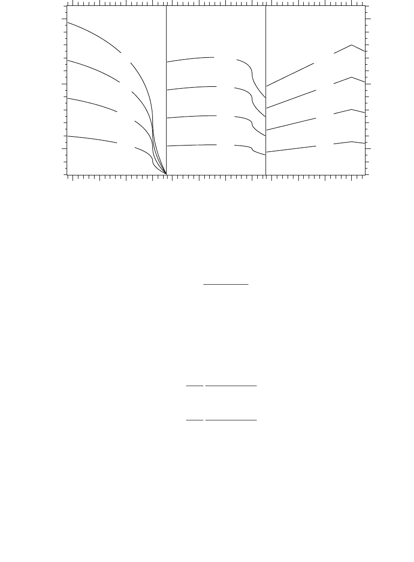
reactive power. Figure 5.8 shows several X/R compensator settings chosen
to provide an operating band from 121 V at light load to 127 V at full load.
The settings were chosen based on a power factor of 0.9, and the curves
show the voltage as the power factor varies. The middle graph with X/R =
0.6 performs well over a wide range of power factors. The graph on the left,
where X/R = 3 which is the line X/R ratio, has the most variation with changes
in power factor. If power factor is lower than we expected, the compensator
will cause high voltages.
With X/R = 0.6 and pf = 0.9, the voltage spread equations are
And, the regulator set voltage is
R
X
set
set
=
-
-
=
VV
pf(I I )
max min
max min
0
R
XR
set
set set
=
-
-
=
086
06
.
.
VV
(I I )
max min
max min
1791_book.fm Page 255 Monday, August 4, 2003 3:20 PM
(C) 2004 by CRC Press LLC
256 Electric Power Distribution Handbook
The universal compensator method fixes compensation at R
set
= 5 V and X
set
= 3 V to give a 6-V compensation range with current ranging up to the
regulator CT rating (General Electric, 1979). For other voltage ranges and
maximum currents, we can use:
And we assume that I
min
= 0, so the regulator set voltage is
V
set
= V
min
To make this even more “cookbook,” we can standardize on values of V
max
and V
min
, for example, values of 126 V and 120 V. If the full-load is the CT
FIGURE 5.8
Regulated voltage based on different compensator settings and power factors with the percent-
age loadings given on the graph. All settings are chosen to operate from 121 V at light load
(33%) to 127 V at full load (100% of the primary CT ratio) at a power factor of 0.9.
R=4.1V, X=12.2V
V
set
=118.0V
25%
50%
75%
100%
0.7 0.8 0.9 1.0
120
125
130
R=7.7V, X=4.6V
V
set
=118.0V
25%
50%
75%
100%
0.7 0.8 0.9 1.0
R=10.0V, X=0.0V
V
set
=118.0V
25%
50%
75%
100%
0.7 0.8 0.9 1.0
Power factor
VV
VV
II
I
set min
max min
max min
min
=-
-
-
R
I
X
I
set
set
=
-
=
-
5
6
3
6
max
max min
max
max min
VV
VV
()
()
1791_book.fm Page 256 Monday, August 4, 2003 3:20 PM
(C) 2004 by CRC Press LLC

Voltage Regulation 257
rating (which we might want in order to be conservative), the default settings
become R
set
= 5 V and X
set
= 3 V. The universal compensation method is easy
yet relatively robust.
With any of the voltage-spread methods of setting the R and X line-drop
compensation, the peak current is an important parameter. If we underesti-
mate the load current, the regulator can overcompensate and cause high volt-
ages (if we do not have a voltage override limiter or if it is disabled). Check
regulator loadings regularly to ensure that the compensation is appropriate.
5.4.1.3 Effects of Regulator Connections
On an open-delta regulator, one regulator is connected leading, and the other
lagging. We need to adjust the compensator settings to account for the 30∞
phase shift. On the leading regulator, the current leads the voltage by 30∞;
so we need to subtract 30∞ from the compensator settings, which is the same
as multiplying by 1–30∞ or (cos 30∞ – j sin 30∞). Modify the settings for the
leading regulator (Cooper Power Systems, 1978; Westinghouse Electric Cor-
poration, 1965) with
R¢
set
= 0.866 R
set
+ 0.5X
set
X¢
set
= 0.866 X
set
– 0.5R
set
And for the lagging regulator we need to add 30∞, which gives
R¢
set
= 0.866 R
set
– 0.5X
set
X¢
set
= 0.866 X
set
+ 0.5R
set
For an X/R ratio above 1.67, R¢
set
is negative on the lagging regulator; and
for a ratio below 0.58, X¢
set
is negative on the leading regulator. Most con-
trollers allow negative compensation.
In the field, how do we tell between the leading and the lagging regulator?
Newer regulator controllers can tell us which is which from phase angle
measurements. For older controllers, we can modify the compensator set-
tings to find out (Lokay and Custard, 1954). Set the resistance value on both
regulators to zero, and set the reactance setting on both to the same nonzero
value. The unit that moves up the most number of tap positions is the lagging
unit (with balanced voltages, this is the unit that goes to the highest raise
position). If the initial reactance setting is not enough, raise the reactance
settings until the leading and lagging units respond differently.
With a closed-delta regulator, all three regulators are connected either
leading or lagging. All three regulators have the same set of compensator
settings; adjust them all with either the leading or the lagging equations
described for the open-delta regulator.
1791_book.fm Page 257 Monday, August 4, 2003 3:20 PM
(C) 2004 by CRC Press LLC

258 Electric Power Distribution Handbook
On a three-phase regulator, even on a delta system, the compensator set-
tings do not need adjustment. The controller accounts for any phase shift
that might occur inside the regulator.
5.4.2 Voltage Override
Use the voltage override feature on the regulator controller. No matter how
we select the line-drop compensation settings, an important feature is an
upper voltage limit on the regulation action. The regulator keeps the regu-
lated voltage below this limit regardless of the line-drop compensation set-
tings. Always use this feature to protect against overvoltages caused by
incorrect line-drop compensation settings or unusually high loadings. This
upper voltage limiter is also called “first house protection,” as it is the first
few customers downstream that could have overvoltages due to regulator
action. With a voltage limit, we can set line-drop compensator settings more
aggressively and not worry about causing overvoltages to customers. On a
regulator without an upper limit (normally older units), increase estimated
peak loadings when calculating line-drop compensation settings in order to
reduce the risk of creating overvoltages. Voltage override functions usually
have a deadband type setting on the voltage limit to prevent repeated tap
changes. For example, we might set a 126-V upper limit with a deadband
of an extra 2 V. Above 128 V the controller immediately taps the regulator
down to 126 V, and between 126 and 128 V the controller prohibits tap raises
(different controllers implement this function somewhat differently; some
include time delays). Even without line-drop compensation, the voltage
override function helps protect against sudden changes in upstream voltages
(the out-of-limit response is normally faster than normal time-delay settings
programmed into regulators).
5.4.3 Regulator Placement
With no feeder regulators, the entire voltage drop on a circuit must be within
the allowed primary voltage range. One feeder regulator can cover primary
voltage drops up to twice the allowed voltage variation. Similarly, two sup-
plementary regulators can cover primary voltage drops up to three times
the allowed variation. For a uniformly distributed load, optimum locations
for two regulators are at distances from the station of approximately 20% of
the feeder length for one and 50% for the other. For one feeder regulator, the
optimum location for a uniformly distributed load is at 3/8 of the line length
from the station.
When placing regulators and choosing compensator settings, allow for
some load growth on the circuit. If a regulator is applied where the load is
right near its rating, it may not be able to withstand the load growth. How-
ever, it is more than just concern about the regulator’s capability. If we want
to keep the primary voltage above 118 V, and we add a regulator to a circuit
1791_book.fm Page 258 Monday, August 4, 2003 3:20 PM
(C) 2004 by CRC Press LLC

Voltage Regulation 259
right at the point where the primary voltage falls to 118 V, that will correct
the voltage profile along the circuit with present loadings. If loadings
increase in the future, the voltage upstream of the regulator will drop below
118 V. As previously discussed, when setting line-drop compensator settings,
the maximum load on the regulator should allow room for load growth to
reduce the chance that the regulator boosts the voltage too much.
Several regulators can be strung together on a circuit. Though this can
meet the steady-state voltage requirements of customers, it will create a very
weak source for them. Flicker problems from motors and other fluctuating
loads are more likely.
Also consider the effect of dropped load on regulators. A common case is
a recloser downstream of a line regulator. If the regulator is tapped up
because of heavy load and the recloser suddenly drops a significant portion
of the load, the voltage downstream of the regulator will pop up until the
regulator controller shifts the taps back down.
5.4.4 Other Regulator Issues
Normally, voltage regulators help with voltage unbalance as each regulator
independently controls its phase. If we aggressively compensate, the line-drop
compensation can cause voltage unbalance. Consider a regulator set to operate
between 120 V at no load and 126 V at full load. If one phase is at 50% load
and the other two are at 0% load, the line-drop compensator will tap to 123 V
on the loaded phase and to 120 V on the unloaded phases. Depending on
customer placements, this may be fine if the voltages correct themselves along
the line. But if the unbalance is due to a large tapped lateral just downstream
of the regulator, the regulator needlessly unbalances the voltages.
Capacitor banks pose special coordination issues with regulators. A fixed
capacitor bank creates a constant voltage rise on the circuit and a constant
reactive contribution to the current. Either fixed or switched, capacitors
upstream of a regulator do not interfere with the regulator’s control action.
Downstream capacitors pose the problem. A capacitor just downstream of
a regulator affects the current that the regulator sees, but it does not mea-
surably change the shape of the voltage profile beyond the regulator. In this
case, we would like the line-drop compensation to ignore the capacitor. The
voltage-spread compensation with a low compensator X/R or the zero-reac-
tance compensator settings work well because they ignore or almost ignore
the reactive current, so it works with fixed or switched banks downstream
of the regulator. The load-center approach is more difficult to get to work
with capacitors.
We do not want to ignore the capacitor at the end of a circuit section we
are regulating because the capacitor significantly alters the profile along the
circuit. In this case, we do not want zero-reactance compensation; we want
some X to compensate for the capacitive current.
Switched capacitors can interact with the tap-changing controls on regu-
lators upstream of the capacitors. This sort of interaction is rare but can
1791_book.fm Page 259 Monday, August 4, 2003 3:20 PM
(C) 2004 by CRC Press LLC

260 Electric Power Distribution Handbook
happen if the capacitor is controlled by voltage (not radio, not time of day,
not vars). A regulator may respond to an upstream or downstream capacitor
switching, but that does not add up to many extra tap changes since the
capacitor switches infrequently. Normally, the capacitor cannot cycle back
and forth against the regulator. The only case might be if the regulator has
negative settings for the reactive line-drop compensation.
With several regulators in series, adjustments to the time delay settings
are the proper way to coordinate operations between units. Set the down-
stream regulator with the longest time delay so it does not change taps
excessively. For multiple regulators, increase the time delay with increasing
distance from the source. Tap changes by a downstream regulator do not
change the voltage upstream, but tap changes by an upstream regulator
affect all downstream regulators. If a downstream regulator acts before the
upstream regulator, the downstream regulator may have to tap again to meet
its set voltage. Making the downstream regulator wait longer prevents it
from tapping unnecessarily. Separate the time delays by at least 10 to 15 sec
to allow the upstream unit to complete tap change operations.
5.5 Station Regulation
Utilities most commonly use load tap changing transformers (LTCs) to con-
trol distribution feeder voltages at the substation. In many cases (short, urban,
thermally limited feeders) an LTC is all the voltage support a circuit needs.
An LTC or a stand-alone voltage regulator must compensate for the voltage
change on the subtransmission circuit as well as the voltage drop through
the transformer. Of these, the voltage drop through the transformer is nor-
mally the largest. Normally, the standard ±10% regulator can accomplish
this. A regulator can hit the end of its range if the load has especially poor
power factor. The voltage drop across a transformer follows:
V
drop
= I
R
· R + I
X
·X
Since a transformer’s X/R ratio is so high, the reactive portion of the load
creates the most voltage drop across the transformer. Consider a 10% imped-
ance transformer at full load with a load power factor of 0.8, which means
the reactive power factor is 0.6. In this case, the voltage drop across the
transformer is 6%. If the subtransmission voltage is 120 V (on a 120-V scale),
the maximum that the regulator can boost the voltage to is 124 V. If this
example had a transformer loaded to more than its base open-air rating
(OA or ONAN), the regulator would be more limited in range. In most
cases, we do not run into this problem as power factors are normally much
better than these.
1791_book.fm Page 260 Monday, August 4, 2003 3:20 PM
(C) 2004 by CRC Press LLC

Voltage Regulation 261
In most cases, bus regulation suffices. For cases where circuits have sig-
nificant voltage drop, individual feeder regulation can be better. Individual
feeder regulation also performs better on circuits with different load cycles.
If commercial feeders are on the same bus as residential feeders, it is less
likely that a bus regulator can keep voltages in line on all circuits. Normally,
we handle this by using bus regulation and supplementary line regulators.
In some cases, individual feeder regulation in the station is more appropriate.
The voltage on feeders serving secondary networks is controlled at the
primary substation with LTC transformers. These circuits are short enough
that feeder regulators are unnecessary. Network feeders are often supplied
by parallel station transformers; paralleling LTC units raises several issues
that are discussed in the next section.
5.5.1 Parallel Operation
With care, we can parallel regulators. The most common situation is in a
substation where a utility wants to parallel two LTC transformers. If two
paralleled transformers do not have the same turns ratio, current will circu-
late to balance the voltages. The circulating current is purely reactive, but it
adds extra loading on the transformer.
Some of the methods to operate LTC transformers in parallel (Jauch, 2001;
Westinghouse Electric Corporation, 1965) include
• Negative-reactance control — The reactance setting in the line-drop
compensator is set to a negative value, so higher reactive current
forces the control to lower taps. The transformer with the higher tap
has more reactive current, and the transformer with the lower tap
is absorbing this reactive current (it looks capacitive to this trans-
former). So, a negative-reactance setting forces the transformer with
the highest tap (and most reactive current) to lower its taps and
bring it into alignment with the other unit. This method limits the
use of line-drop compensation and can lead to lower bus voltages.
• Master-follower — One controller, the master, regulates the voltage
and signals the other tap changers (the followers) to match the tap
setting. The master control normally gets feedback from the follow-
ers to confirm their operation.
• Var balancing — The controller adjusts taps as required to equalize
the vars flowing in parallel transformers. Auxiliary circuitry is
required. This method has the advantage that it works with trans-
formers fed from separate transmission sources.
• Circulating current method — This is the most common control. Aux-
iliary circuitry is added to separate the load current through each
transformer from the circulating current. Each transformer LTC con-
trol is fed the load current. The controller adjusts taps to minimize
1791_book.fm Page 261 Monday, August 4, 2003 3:20 PM
(C) 2004 by CRC Press LLC

262 Electric Power Distribution Handbook
the difference in current between parallel units. Removing a unit
does not require changing controller settings.
The complications associated with paralleling regulators are another rea-
son utilities normally avoid closed bus ties in distribution substations.
5.5.2 Bus Regulation Settings
Although too often left unused, bus regulators (whether stand-alone regu-
lators or load tap changing transformers) can use line-drop compensation.
The concept of a load center rarely has good meaning for a bus supporting
several circuits, but the voltage spread methods allow the regulator to boost
voltage under heavy load.
The voltage-spread equations assume that the power factor at full load is
the same as the power factor at light load. If the power factor is different at
light and peak loads, we can use this information to provide more precise
settings. We could solve the following to find new R and X settings with
different power factors
V
max
– V
min
= (pf
max
◊ R
set
+ qf
max
◊ X
set
)I
max
– (pf
min
◊ R
set
+ qf
min
◊ X
set
)I
min
However, it is easier to use the equations in Section 5.4.1.2 and use the
average of the power factor at peak load and the power factor at light load.
With line-drop compensation for bus regulation, the voltage-override feature
helps to ensure that the LTC or regulator does not cause excessive voltages.
Individual substation feeder regulators are set the same as line feeder
regulators. We can tune controller settings more precisely based on the
individual characteristics of a given feeder. If the first part of the feeder is
an express feeder with no load on it, we could boost the voltage higher than
normal, especially if the circuit is voltage limited. Our main constraint is
making sure that the first customer does not have high voltage.
5.6 Line Loss and Voltage Drop Relationships
Line losses are from the line current flowing through the resistance of the
conductors. After distribution transformer losses, primary line losses are the
largest cause of losses on the distribution system. Like any resistive losses,
line losses are a function of the current squared multiplied by the resistance
(I
2
R). Ways to reduce line losses include
• Use a higher system voltage
• Balance circuits
1791_book.fm Page 262 Monday, August 4, 2003 3:20 PM
(C) 2004 by CRC Press LLC

Voltage Regulation 263
• Convert single-phase circuits to three-phase circuits
• Reduce loads
• Increase power factor (capacitors)
• Reconductor with a larger size
Because losses are a function of the current squared, most losses occur on
the primary near the substation. Losses occur regardless of the power factor
of the circuit. Reducing the reactive portion of current reduces the total
current, which can significantly impact losses.
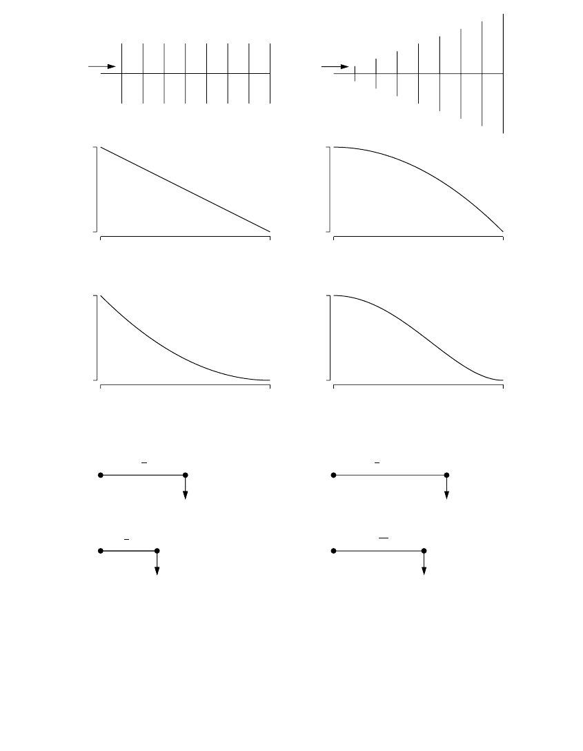
Approximations using uniform load distributions are useful. A uniformly
distributed load along a circuit of length l has the same losses as a single
lumped load placed at a length of l/3 from the source end. For voltage drop,
the equivalent circuits are different: a uniformly distributed load along a
circuit of length l has the same voltage drop as a single lumped load placed
at a length of l/2 from the source end. This 1/2 rule for voltage drop and
the 1/3 rule for losses are helpful approximations when doing hand calcu-
lations or when making simplifications to enter in a load-flow program.
For a uniformly increasing load, the equivalent lumped load is at 0.53l of
the length from the source. Figure 5.9 shows equivalent circuits for a uniform
load and a uniformly increasing load.
Line losses decrease as operating voltage increases because the current
decreases. Schultz (1978) derived several expressions for primary feeder I
2
R
losses on circuits with uniform load densities. His analysis showed that most
15 to 35 kV circuits are not voltage-drop limited — most are thermally
limited. As the system voltage varies, the losses change the most for voltage-
limited circuits (Schultz, 1978):
where
V
1
, V
2
= voltage on circuits 1 and 2
L
1
, L
2
= feeder I
2
R losses on circuits 1 and 2
On a system-wide basis, losses are expected to change with voltage with
an exponent somewhere between 2/3 and 2.
Losses, voltage drop, and capacity are all interrelated. Three-phase circuits
have the highest power transfer capacity, the lowest voltage drop, and the
lowest losses. Table 5.7 compares capacity, voltage drop, and losses of a
balanced three-phase system with several other phasing configurations.
L
V
V
L
L
V
V
L
2
1
2
2
1
2
1
2
23
1
=
Ê
Ë
Á
ˆ
¯
˜
=
Ê
Ë
Á
ˆ
¯
˜
for a voltage-limited circuit
for a thermally-limited circuit
/
1791_book.fm Page 263 Monday, August 4, 2003 3:20 PM
(C) 2004 by CRC Press LLC
264 Electric Power Distribution Handbook
FIGURE 5.9
Equivalent circuits of uniform loads.
Uniform load
Uniformly increasing load
0
I
0
I
2
0
l
0
I
l
0
l
0
l
0
I
I
2
I
I
I
Equivalent circuits with one lumped load
Equivalent voltage drop
Equivalent linelosses
1
2
l
1
3
l
Equivalent voltage drop
1
2
l
I
I
Equivalent voltage drop
2
3
l
8
15
l
Equivalent linelosses
Line currents
Line currents squared
0
1791_book.fm Page 264 Monday, August 4, 2003 3:20 PM
(C) 2004 by CRC Press LLC