Short T.A. Electric Power Distribution Handbook
Подождите немного. Документ загружается.

276
Electric Power Distribution Handbook
So, the discharge resistor must continually dissipate at least the following
power in watts:
where
Q
kvar
is the capacitor rating (single or three phase). For 7.2-kV capac-
itors, the lower bound on losses is 0.047 W/kvar.
Some utilities use a shorting bar across the terminals of capacitors during
shipping and in storage. The standard recommends waiting for 5 min to
allow the capacitor to discharge through the internal resistor.
Capacitors have very low losses, so they run very cool. But capacitors are
very sensitive to temperature and are rated for lower temperatures than
other power system equipment such as cables or transformers. Capacitors
do not have load cycles like transformers; they are always at full load. Also,
capacitors are designed to operate at high dielectric stresses, so they have
less margin for degraded insulation. Standards specify an upper limit for
application of 40 or 46
∞
C depending on arrangement (see Table 6.5). These
limits assume unrestricted ventilation and direct sunlight. At the lower end,
IEEE standard 18 specifies that capacitors shall be able to operate continu-
ously in a –40˚C ambient.
6.2 Released Capacity
In addition to reducing losses and improving voltage, capacitors release
capacity. Improving the power factor increases the amount of real-power
load the circuit can supply. Using capacitors to supply reactive power
reduces the amount of current in the line, so a line of a given ampacity can
TABLE 6.5
Maximum Ambient Temperatures for Capacitor Application
Mounting Arrangement
Ambient Air Temperature
(˚C)
4-h Average
a
Isolated capacitor 46
Single row of capacitors 46
Multiple rows and tiers of capacitors 40
Metal-enclosed or -housed equipments 40
a
The arithmetic average of the four consecutive highest hourly read-
ings during the hottest day expected at that location.
Source:
IEEE Std. 18-2002. Copyright 2002 IEEE. All rights reserved.
P
Q
V
watts
kvar
=-
Ê
Ë
Á
ˆ
¯
˜
113 2
35 36
.
ln
.
1791_book.fm Page 276 Monday, August 4, 2003 3:20 PM
(C) 2004 by CRC Press LLC
Capacitor Application
277
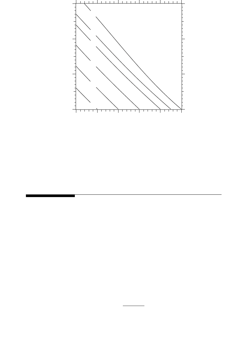
carry more load. Figure 6.4 shows that capacitors release significant capacity,
especially if the original power factor is low. Figure 6.5 shows another way
to view the extra capacity, as a function of the size of capacitor added.
6.3 Voltage Support
Capacitors are constant-impedance devices. At higher voltages, capacitors
draw more current and produce more reactive power as
I
=
I
rated
V
pu
and
Q
kvar
=
Q
rated
V
pu
2
where
V
pu
is the voltage in per unit of the capacitor’s voltage rating. Capac-
itors applied at voltages other than their rating provide vars in proportion
to the per-unit voltage squared.
Capacitors provide almost a fixed voltage rise. The reactive current
through the system impedance causes a voltage rise in percent of
FIGURE 6.4
Released capacity with improved power factor.
0.60
0.70
0.80
0.90
0.95
1.00
Corrected power factor
0.5 0.6 0.7 0.8 0.9 1.0
0
20
40
60
Original power factor
Extra capacity, percent of the original load
V
QX
V
rise
kvar
L
kV l l
=
-
10
2
,
1791_book.fm Page 277 Monday, August 4, 2003 3:20 PM
(C) 2004 by CRC Press LLC
278
Electric Power Distribution Handbook
where
X
L
= positive-sequence system impedance from the source to the capac-
itor,
W
V
kV, l-l
= line-to-line system voltage, kV
Q
kvar
= three-phase bank rating, kvar
While this equation is very good for most applications, it is not exactly
right because the capacitive current changes in proportion to voltage. At a
higher operating voltage, a capacitor creates more voltage rise than the
equation predicts.
Since the amount of voltage rise is dependent on the impedance upstream
of the bank, to get the voltage boost along the entire circuit, put the capacitor
at the end of the circuit. The best location for voltage support depends on
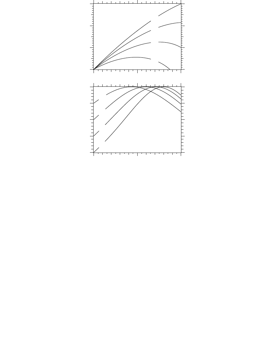
where the voltage support is needed. Figure 6.6 shows how a capacitor
changes the voltage profile along a circuit. Unlike a regulator, a capacitor
changes the voltage profile upstream of the bank.
Table 6.6 shows the percentage voltage rise from capacitors for common
conductors at different voltages. This table excludes the station transformer
FIGURE 6.5
Extra capacity as a function of capacitor size.
0.6
0.7
0.8
0.9
Original power factor
0 50 100
0.6
0.7
0.8
0.9
1.0
0.6
0.7
0.8
0.9
Original power factor:
0 50 100
0
20
40
60
Capacitor kvar in percent of original load kVA
New power factor
Extra capacity in
percent of the original load
1791_book.fm Page 278 Monday, August 4, 2003 3:20 PM
(C) 2004 by CRC Press LLC
Capacitor Application
279
FIGURE 6.6
Voltage profiles after addition of a capacitor bank. (Copyright © 2002. Electric Power Research
Institute. 1001691.
Improved Reliability of Switched Capacitor Banks and Capacitor Technology.
Re-
printed with permission.)
TABLE 6.6
Percent Voltage Rise for Various Conductors and Voltage Levels
Conductor Size
X
L
WW
WW
/mi
Percent Voltage Rise per Mile with 100 kvar per Phase
Line-to-Line System Voltage, kV
4.8 12.47 24.9 34.5
4 0.792 1.031 0.153 0.038 0.020
2 0.764 0.995 0.147 0.037 0.019
1/0 0.736 0.958 0.142 0.036 0.019
4/0 0.694 0.903 0.134 0.034 0.017
350 0.656 0.854 0.127 0.032 0.017
500 0.635 0.826 0.122 0.031 0.016
750 0.608 0.791 0.117 0.029 0.015
Note:
Impedance are for all-aluminum conductors with GMD=4.8 ft.
Voltage rise from the capacitor
Voltage profile with the capacitor
Volta
g
e
p
rofile without the ca
p
acitor
100
102
104
96
98
100
With no load
With load
Voltage profile without the capacitor
Fee
d
er vo
l
tage, percent
1791_book.fm Page 279 Monday, August 4, 2003 3:20 PM
(C) 2004 by CRC Press LLC

280
Electric Power Distribution Handbook
impedance but still provides a useful approximation. Inductance does not
change much with conductor size; the voltage change stays the same over
a wide range of conductor sizes. For 15-kV class systems, capacitors increase
the voltage by about 0.12% per mi per 100 kvar per phase.
On switched capacitor banks, the voltage change constrains the size of
banks at some locations. Normally, utilities limit the voltage change to 3 to
4%. On a 12.47-kV circuit, a three-phase 1200-kvar bank boosts the voltage
4% at about 8 mi from the substation. To keep within a 4% limit, 1200-kvar
banks must only be used within the first 8 mi of the station.
6.4 Reducing Line Losses
One of the main benefits of applying capacitors is that they can reduce
distribution line losses. Losses come from current through the resistance of
conductors. Some of that current transmits real power, but some flows to
supply reactive power. Reactive power provides magnetizing for motors and
other inductive loads. Reactive power does not spin kWh meters and per-
forms no useful work, but it must be supplied. Using capacitors to supply
reactive power reduces the amount of current in the line. Since line losses
are a function of the current squared,
I
2
R
, reducing reactive power flow on
lines significantly reduces losses.
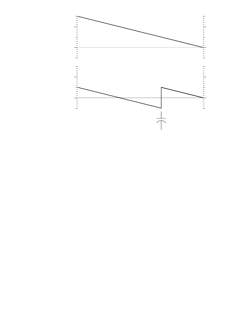
Engineers widely use the “2/3 rule” for sizing and placing capacitors to
optimally reduce losses. Neagle and Samson (1956) developed a capacitor
placement approach for uniformly distributed lines and showed that the
optimal capacitor location is the point on the circuit where the reactive power
flow equals half of the capacitor var rating. From this, they developed the
2/3 rule for selecting and placing capacitors. For a uniformly distributed
load, the optimal size capacitor is 2/3 of the var requirements of the circuit.
The optimal placement of this capacitor is 2/3 of the distance from the
substation to the end of the line. For this optimal placement for a uniformly
distributed load, the substation source provides vars for the first 1/3 of the
circuit, and the capacitor provides vars for the last 2/3 of the circuit (see
Figure 6.7).
A generalization of the 2/3 rule for applying
n
capacitors to a circuit is to
size each one to 2/(2
n
+1) of the circuit var requirements. Apply them equally
spaced, starting at a distance of 2/(2
n
+1) of the total line length from the
substation and adding the rest of the units at intervals of 2/(2
n
+1) of the
total line length. The total vars supplied by the capacitors is 2
n
/(2
n
+1) of
the circuit’s var requirements. So to apply three capacitors, size each to 2/7
of the total vars needed, and locate them at per unit distances of 2/7, 4/7,
and 6/7 of the line length from the substation.
Grainger and Lee (1981) provide an optimal yet simple method for placing
fixed capacitors on a circuit with any load profile, not just a uniformly
1791_book.fm Page 280 Monday, August 4, 2003 3:20 PM
(C) 2004 by CRC Press LLC
Capacitor Application
281
distributed load. With the Grainger/Lee method, we use the reactive load
profile of a circuit to place capacitors. The basic idea is again to locate banks
at points on the circuit where the reactive power equals one half of the
capacitor var rating. With this 1/2
-kvar rule
, the capacitor supplies half of its
vars downstream, and half are sent upstream. The basic steps of this
approach are:
1.
Pick a size —
Choose a standard size capacitor. Common sizes range
from 300 to 1200 kvar, with some sized up to 2400 kvar. If the bank
size is 2/3 of the feeder requirement, we only need one bank. If the
size is 1/6 of the feeder requirement, we need five capacitor banks.
2.
Locate the first bank
— Start from the end of the circuit. Locate the
first bank at the point on the circuit where var flows on the line are
equal to half of the capacitor var rating.
3.
Locate subsequent banks
— After a bank is placed, reevaluate the var
profile. Move upstream until the next point where the var flow
equals half of the capacitor rating. Continue placing banks in this
manner until no more locations meet the criteria.
There is no reason we have to stick with the same size of banks. We could
place a 300-kvar bank where the var flow equals 150 kvar, then apply a 600-
FIGURE 6.7
Optimal capacitor loss reduction using the two-thirds rule. (Copyright © 2002. Electric Power
Research Institute. 1001691.
Improved Reliability of Switched Capacitor Banks and Capacitor Tech-
nology.
Reprinted with permission.)
0
2
0
2
reactive line
flow
Mvar
Uniform load—2/3’s rule for placing one capacitor
Substation
Feeder end
0
2
0
2
reactive line
flow
Mvar
Without capacitors
2-Mvar bank
Without capacitors
With one capacitor
1791_book.fm Page 281 Monday, August 4, 2003 3:20 PM
(C) 2004 by CRC Press LLC
282
Electric Power Distribution Handbook
kvar bank where the var flow equals 300 kvar, and finally apply a 450-kvar
bank where the var flow equals 225 kvar. Normally, it is more efficient to
use standardized bank sizes, but different size banks at different portions of
the feeder might help with voltage profiles.
The 1/2-kvar method works for any section of line. If a line has major
branches, we can apply capacitors along the branches using the same
method. Start at the end, move upstream, and apply capacitors at points
where the line’s kvar flow equals half of the kvar rating of the capacitor. It
also works for lines that already have capacitors (it does not optimize the
placement of all of the banks, but it optimizes placement of new banks). For
large industrial loads, the best location is often going to be right at the load.
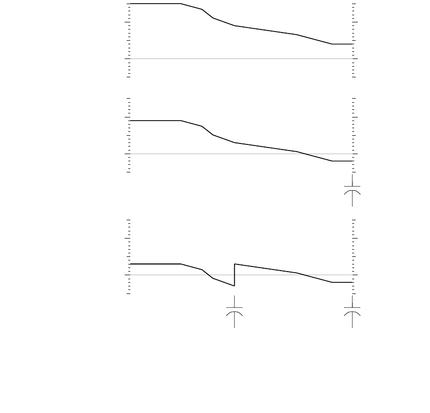
Figure 6.8 shows the optimal placement of 1200-kvar banks on an example
circuit. Since the end of the circuit has reactive load above the 600-kvar
threshold for sizing 1200-kvar banks, we apply the first capacitor at the end
FIGURE 6.8
Placement of 1200-kvar banks using the 1/2-kvar method.
0
2
0
2
reactive line
flow
Mvar
Substation Feeder end
0
2
0
2
reactive line
flow
Mvar
Without capacitors
1200 kvar
After the first capacitor placement
0
2
0
2
1200 kvar
After the second capacitor placement
1200 kvar1200 kvar
reactive line
flow
Mvar
1791_book.fm Page 282 Monday, August 4, 2003 3:20 PM
(C) 2004 by CRC Press LLC
Capacitor Application
283
of the circuit. (The circuit at the end of the line could be one large customer
or branches off the main line.) The second bank goes near the middle. The
circuit has an express feeder near the start. Another 1200-kvar bank could
go in just after the express feeder, but that does not buy us anything. The
two capacitors total 2400 kvar, and the feeder load is 3000 kvar. We really
need another 600-kvar capacitor to zero out the var flow before it gets to the
express feeder.
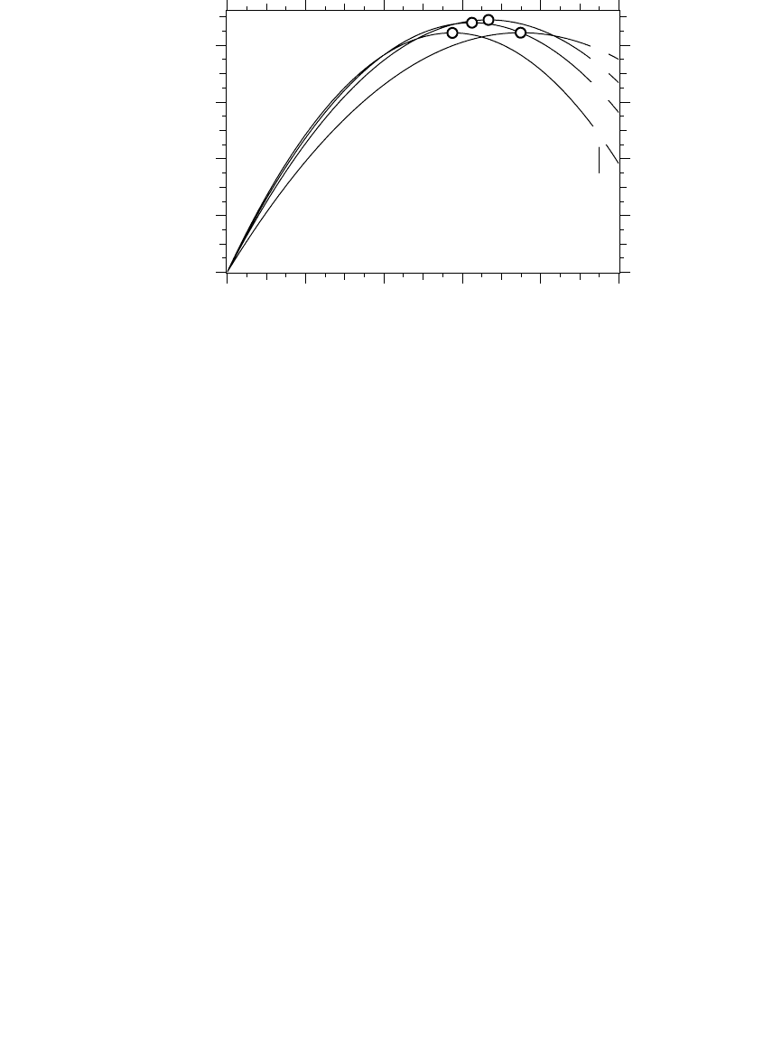
Fortunately, capacitor placement and sizing does not have to be exact.
Quite good loss reduction occurs even if sizing and placement are not exactly
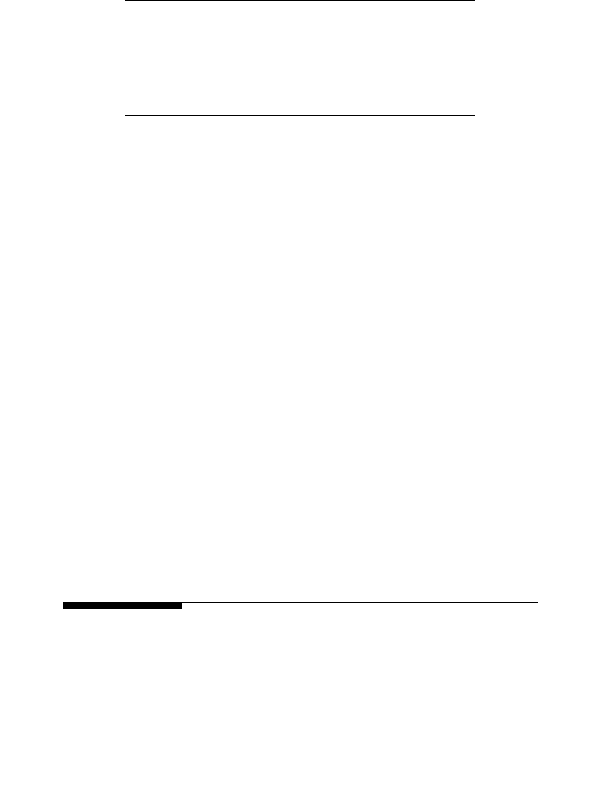
optimum. Figure 6.9 shows the loss reduction for one fixed capacitor on a
circuit with a uniform load. The 2/3 rule specifies that the optimum distance
is 2/3 of the distance from the substation and 2/3 of the circuit’s var require-
ment. As long as the size and location are somewhat close (within 10%), the
not-quite-optimal capacitor placement provides almost as much loss reduc-
tion as the optimal placement.
Consider the voltage impacts of capacitors. Under light load, check that
the capacitors have not raised the voltages above allowable standards. If
voltage limits are exceeded, reduce the size of the capacitor banks or the
number of capacitor banks until voltage limits are not exceeded. If additional
loss reduction is desired, consider switched banks as discussed below.
6.4.1 Energy Losses
Use the average reactive loading profile to optimally size and place capaci-
tors for energy losses. If we use the peak-load case, the 1/2-kvar method
FIGURE 6.9
Sensitivity to losses of sizing and placing one capacitor on a circuit with a uniform load. (The
circles mark the optimum location for each of the sizes shown.)
50
67
75
85
Capacitor size as a percentage
of the feeder’s reactive load
0 20 40 60 80 100
0
20
40
60
80
Capacitor location, percent of the total line length
Loss reduction in percent
of the total losses due to reactive power
1791_book.fm Page 283 Monday, August 4, 2003 3:20 PM
(C) 2004 by CRC Press LLC
284
Electric Power Distribution Handbook
optimizes losses during the peak load. If we have a load-flow case with the
average reactive load, the 1/2-kvar method or the 2/3 rule optimizes energy
losses. This leads to more separation between banks and less kvars applied
than if we optimize for peak losses.
If an average system case is not available, then we can estimate it by scaling
the peak load case by the reactive load factor,
RLF
:
The reactive load factor is similar to the traditional load factor except that
it only considers the reactive portion of the load. If we have no information
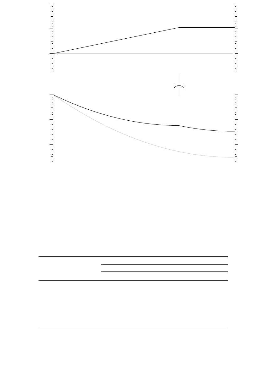
on the reactive load factor, use the total load factor. Normally, the reactive
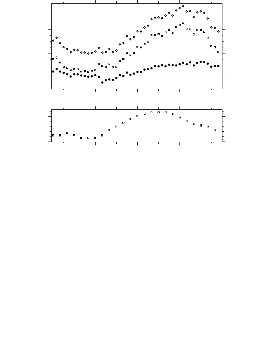
load factor is higher than the total load factor. Figure 6.10 shows an example
of power profiles; the real power (kW) fluctuates significantly more than the
reactive power (kvar).
6.5 Switched Banks
Switched banks provide benefits under the following situations:
•
More loss reduction
— As the reactive loading on the circuit changes,
we reduce losses by switching banks on and off to track these
changes.
•
Voltage limits
— If optimally applied banks under the average load-
ing scenario cause excessive voltage under light load, then use
switched banks.
In addition, automated capacitors — those with communications — have
the flexibility to also use distribution vars for transmission support.
Fixed banks are relatively easy to site and size optimally. Switched banks
are more difficult. Optimally sizing capacitors, placing them, and deciding
when to switch them are difficult tasks. Several software packages are avail-
able that can optimize this solution. This is an intensely studied area, and
technical literature documents several approaches (among these Carlisle and
El-Keib, 2000; Grainger and Civanlar, 1985; Shyh, 2000).
To place switched capacitors using the 1/2-kvar method, again place the
banks at the location where the line kvar equals half the bank rating. But
instead of using the average reactive load profile (the rule for fixed banks),
use the average reactive flow during the time the capacitor is on. With time-
switched banks and information on load profiles (or typical load profiles),
RLF =
Average kvar Demand
Peak kvar Demand
1791_book.fm Page 284 Monday, August 4, 2003 3:20 PM
(C) 2004 by CRC Press LLC
Capacitor Application
285
we can pick the on time and the off time and determine the proper sizing
based on the average reactive flow between the on and off times. Or, we can
place a bank and pick the on and off times such that the average reactive
line flow while the bank is switched on equals half of the bank rating. In
these cases, we have specified the size and either the placement or switching
time. To more generally optimize — including sizing, placement, number of
banks, and switching time — we must use a computer, which iterates to find
a solution [see Lee and Grainger (1981) for one example].
Combinations of fixed and switched banks are more difficult. The fol-
lowing approach is not optimal but gives reasonable results. Apply fixed
banks to the circuit with the 1/2-kvar rule based on the light-load case.
Check voltages. If there are undervoltages, increase the size of capacitors,
use more capacitor banks, or add regulators. Now, look for locations suit-
able for switched banks. Again, use the average reactive line flows for the
time when the capacitor is on (with the already-placed fixed capacitors in
the circuit model). When applying switched capacitors, check the light-
load case for possible overvoltages, and check the peak-load case for under-
voltages.
FIGURE 6.10
Example of real and reactive power profiles on a residential feeder on a peak summer day with
95% air conditioning. (Data from East Central Oklahoma Electric Cooperative, Inc. [RUS 1724D-
112, 2001].)
kVA
kW
kvar
00:00 06:00 12:00 18:00 24:00
40
60
80
100
00:00 06:00 12:00 18:00 24:00
70
80
90
Percent of the daily kVA peakTemperature, degF
1791_book.fm Page 285 Monday, August 4, 2003 3:20 PM
(C) 2004 by CRC Press LLC