Short T.A. Electric Power Distribution Handbook
Подождите немного. Документ загружается.

Voltage Sags and Momentary Interruptions 507
10.7.3 Voltage Class
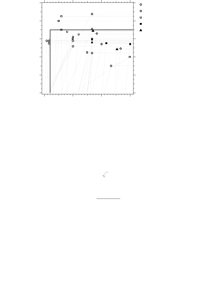
Figure 10.18 shows that 5-kV systems have much lower numbers of voltage
sags and interruptions. Lower voltage systems have less feeder exposure,
and higher line impedance relative to the station transformer. Fault rates are
often lower on 5-kV systems. Somewhat surprisingly, the 25 and 35-kV
systems were not worse than the 15-kV systems.
10.7.4 Comparison and Ranking of Factors
We analyzed data available on the DPQ site characteristics to determine what
parameters most affected power quality events. Figure 10.19 shows the vari-
ations of SARFI
ITIC
with site characteristics.
The three most significant predictors of excursions below the lower ITI
curve are:
1. Circuit exposure — The total exposure on the circuit including three-
phase and single-phase portions is a good predictor of voltage sags.
Any fault on the circuit sags the voltage.
2. Lightning — Lightning causes many faults on distribution systems,
and lightning strongly correlates with voltage sags (based on the 10-
year average, 1988–98, from the U.S. National Lightning Detection
Network). In addition, lightning predicts weather patterns — areas
with high lightning tend to have more storms and more wind and
tree-related faults.
3. Transformer impedance and number of feeders — The n
f
◊ kV
2
/MVA
xfrmr
term in Figure 10.19 contains the number of feeders off of the trans-
former bus along with an estimate of the transformer impedance.
The transformer impedance is Z
%
kV
2
/MVA; but since the per-unit
FIGURE 10.18
Comparison of feeder sites by voltage class in the DPQ data.
5 kV
15 kV
25 & 35 kV
0 20 40 60
0
25
50
75
100
0
25
50
75
100
0
25
50
75
100
Sarfi
ITIC
Percent of locations
exceeding the x-axis value
1791_book.fm Page 507 Monday, August 4, 2003 3:20 PM
(C) 2004 by CRC Press LLC
508 Electric Power Distribution Handbook
impedance of station transformers is roughly constant (7 to 10%),
we use kV
2
/MVA.
This last term requires a bit more explanation. The number of bus sags is
directly proportional to n
f
, the number of feeders off the bus and to Z
S
, the
source impedance (a lower station transformer impedance — a bigger trans-
former or lower percent impedance — improves voltage sags at the station
bus). We approximate these two terms as n
f
◊ kV
2
/MVA
xfrmr
.
FIGURE 10.19
Variations in the number of excursions below the lower ITI curve (which are mainly voltage
sags) vs. various site parameters. The correlation coefficients (r) are given in the upper-left
corner of each plot.
Total feeder exposure, miles
0.33
SARF-IITIC
020406080
020406080 120
Total 3-phase exposure, miles
0.29
01020304050
Flash density, flashes km
2
year
0.24
024681012
n
f
kV
base
2
MVA
xfmr
0.41
SARF-IITIC
020406080 120
020406080 120
Nominal line-to-line voltage, kV
0.2
51015202530
Station transformer base MVA
0.08
020406080100
Percentage tree coverage
0.08
SARF-IITIC
10 20 30 40 50 60 70
020406080 120
Number of feeders
0.05
1234567
1791_book.fm Page 508 Monday, August 4, 2003 3:20 PM
(C) 2004 by CRC Press LLC

Voltage Sags and Momentary Interruptions 509
Other variables have much less impact on the number of voltage sags than
the three main parameters given.
10.8 Prediction of Quality Indicators Based on Site
Characteristics
We derive a formula for predicting the number of events for a quality indi-
cator based on a few of the characteristics of the site. If no measurement or
historical data is available, this is useful in estimating the utility-side quality.
Regression techniques are commonly used to find a model prediction
formula. A generalized linear model is a least-squares fit to an equation of
the following form:
The x’s are site characteristics (such as base voltage or lightning flash
density), and the a’s are coefficients fitted to the model. The generalized
linear model is somewhat different from a standard linear model; we used
a generalization where the distribution of the error e is assumed to be a
gamma distribution rather than a normal distribution in a strictly linear
model. A gamma distribution skews to the right, like the log-normal
distribution.
A model for estimating SARFI
ITIC
is
where
N
ITIC
= predicted annual number of events which fall under the lower
ITI curve
l = total exposure (including three-phase and single-phase por-
tions) on the circuit, mi (multiply kilometers by 1.609)
N
g
= lightning ground flash density, flashes/km
2
/year
kV = base line-to-line voltage, kV
n
f
= total number of feeders off of the substation bus
MVA
xfmr
= station transformer base rating (open-air rating), MVA
If any of the circuit characteristics are unknown, we could use the follow-
ing medians from the DPQ data:
yax ax ax
nn
=++++
11 2 2
L e
NlN
nkV
MVA
ITIC g
f
xfmr
=+ + +
◊
+
474 076 247 0192
82
2
.. . .
. if moderate to heavy tree coverage
1791_book.fm Page 509 Monday, August 4, 2003 3:20 PM
(C) 2004 by CRC Press LLC
510 Electric Power Distribution Handbook
where
l = 14.5 mi (23.4 km)
N
g
= 2.57 flashes/km
2
/year
= 25
All three variable terms in the linear regression are significant to at least
99% (there is less than a 1% chance that the terms of the model do not
influence the prediction). The tree coverage term is less certain; there is a 9%
chance that the term is not significant. We based the tree coverage term on
the University of Maryland’s Global Land Cover Facility data from the
Advanced Very High Resolution Radiometer (AVHRR). Half of the DPQ sites
had more than 19% of the land area covered by trees, which we defined as
“moderate to heavy tree cover.”
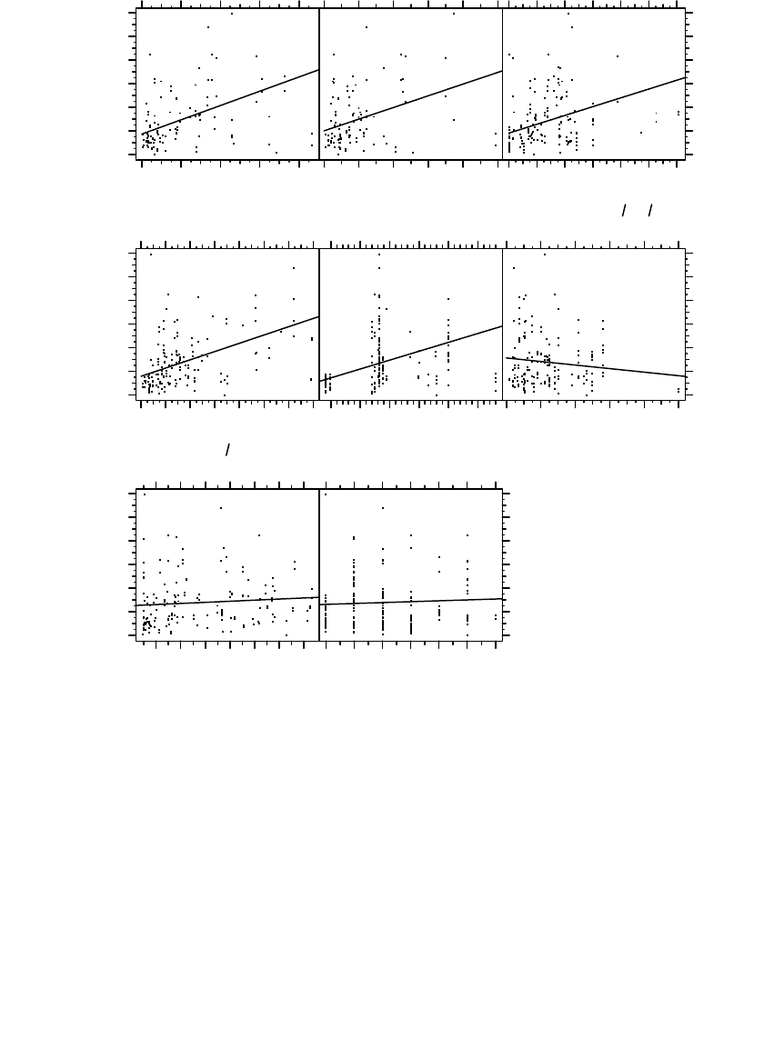
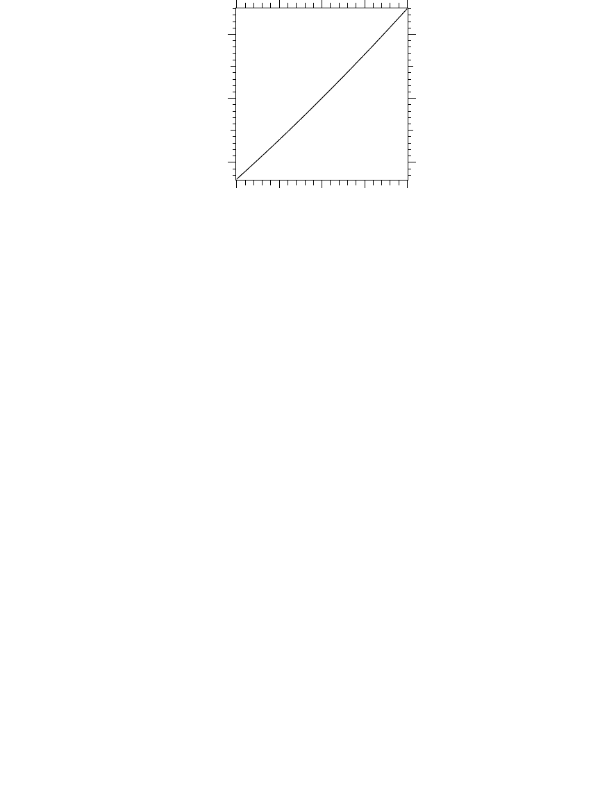
How good is the model? It is decent given all the factors that affect sags
and momentary interruptions and inherent variability. Given the variability
of power quality events, it is surprising that the model is this good: 34% of
the values are within 25% of the prediction, and 60% of the values are within
50% of the prediction. See Figure 10.20 for the prediction scatter.
For an example 12.47-kV case with three feeders, a 25-MVA transformer,
a flash density of 4 flashes/km
2
/year, moderate tree coverage, and a total
exposure of 32 km, the model predicts 29.8 events per year. For this case, the
data shows a prediction interval with a 50% confidence level of between 15.6
and 34.2 events per year (the 90% confidence prediction interval is between
0 and 68.3). The data is so dispersed that the model is not good enough to
use for precision estimates (such as in a contract for premium power).
FIGURE 10.20
Actual values vs. predicted values for the model predicting the annual average number of
events below the lower ITI curve.
nkV
MVA
f
xfmr
◊
2
0102030405060
020406080
Predicted value
Actual value
0102030405060
020406080
1791_book.fm Page 510 Monday, August 4, 2003 3:20 PM
(C) 2004 by CRC Press LLC

Voltage Sags and Momentary Interruptions 511
The site characteristics most affecting sags but not included in this model
(because no information was available) are (1) subtransmission exposure and
characteristics and (2) percentage of the circuit that was underground.
A reasonable model for predicting momentary interruptions is
where
N
10
= the predicted annual number of events with voltage less than 10% of
nominal for more than 0.4 sec
l
3
= the three-phase circuit exposure, mi
The parameters differ somewhat from SARFI
ITIC
predictors. Two of the
strongest indicators of momentary interruptions are load density and three-
phase circuit exposure. Other significant parameters are the lightning activity
and a term with voltage, number of feeders, and transformer MVA. The
model is not as good as the ITI model, but all parameters have more than a
95% probability of affecting the result. The site characteristic most affecting
momentaries that is not included in the model for lack of information is
whether fuse saving is used.
10.9 Equipment Sensitivities
10.9.1 Computers and Electronic Power Supplies
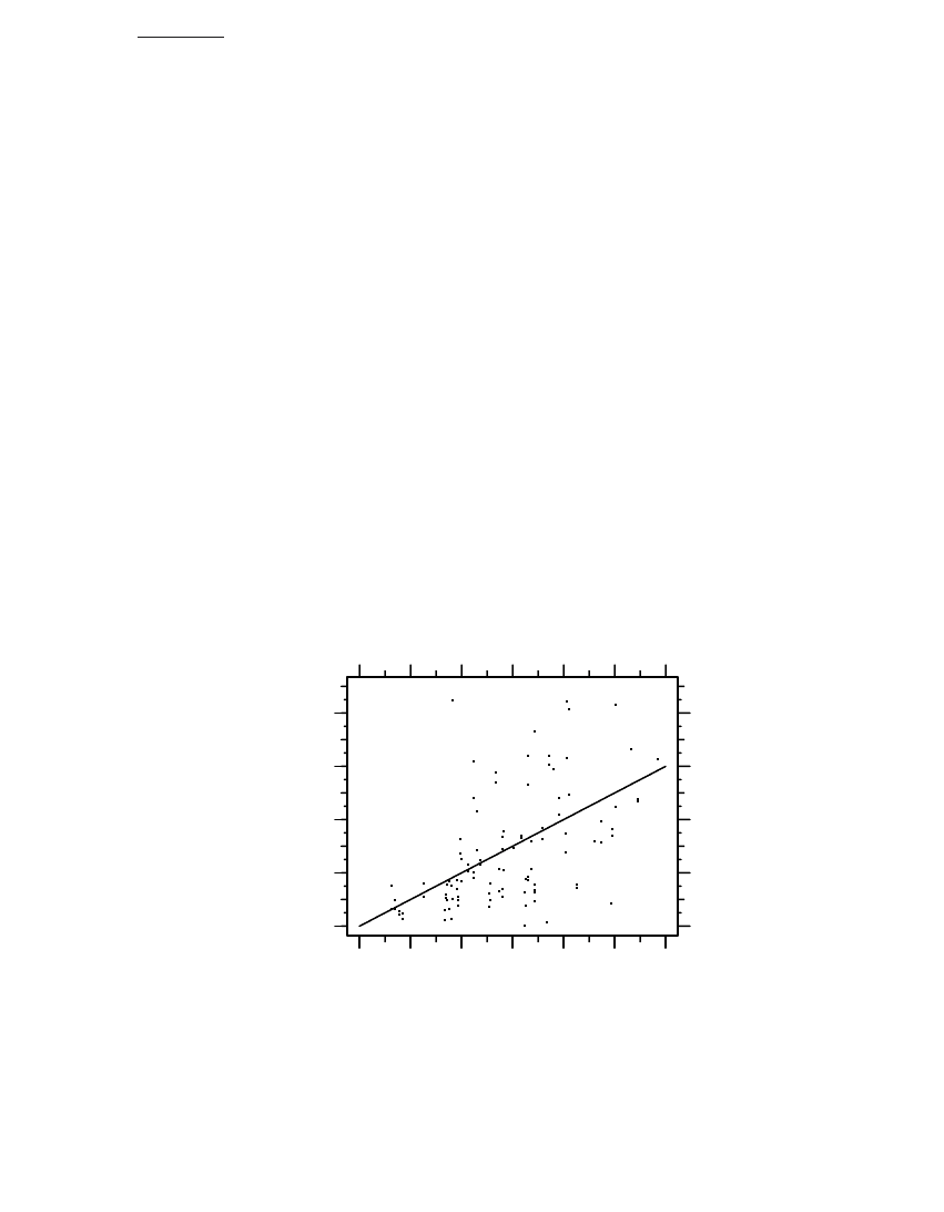
Computers and other equipment with electronic power supplies are the most
widely found equipment that is sensitive to power quality disturbances. The
power supply is typically a switched mode power supply as shown in Figure
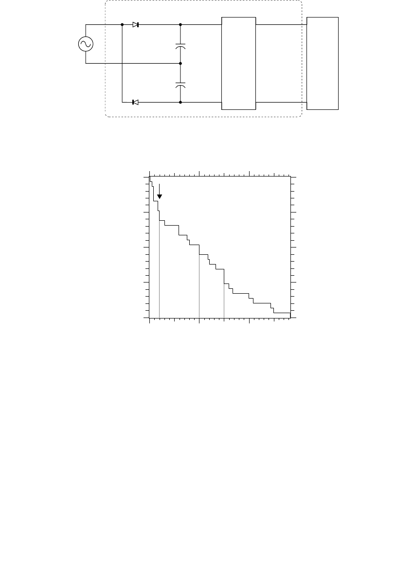
10.21. Computers have a wide range of sensitivities. The ride-through capa-
bility for interruptions of several computers is summarized in Figure 10.22.
Many of the computers had ride through of more than 0.1 sec (0.28 sec was
the best of this set of studies), and some could not even ride through a 0.01-
sec interruption.
The ride-through capability of computers is close to rectangular. Two
points describe the characteristic on a volt-time curve: the interruption ride
through time and the steady-state ride-through point. There is usually a
steep transition between the interruption ride-through point and the
steady-state ride-through point. Other characteristics of computer ride
through are:
NlN
nkV
MVA
g
f
xfmr
10 3
552
029
161
030 027 124=
-
Ê
Ë
Á
Á
ˆ
¯
˜
˜
++ +
◊
.
.
.
.. .
if Rural
if Suburban
if Urban
1791_book.fm Page 511 Monday, August 4, 2003 3:20 PM
(C) 2004 by CRC Press LLC
512 Electric Power Distribution Handbook
• There is little difference between the performance when the com-
puter is processing or accessing disk and when the computer is idle.
• The point on the waveform when the disruption occurs does not
matter.
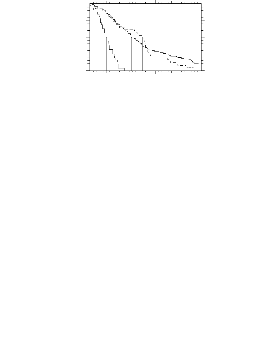
Figure 10.23 shows volt-time sensitivities of computers from several stud-
ies. The most sensitive units, those that violate the ITI curve, were made and
tested before the ITI curve was created. That is not much of an excuse as the
most sensitive computers also violated the CBEMA curve which was avail-
able to the manufacturers at that time (remember, there is no standard that
requires testing computers to meet the ITI/CBEMA curve).
FIGURE 10.21
Switch-mode power supply used in most computers.
FIGURE 10.22
Capability of computers to ride through an interruption (n = 27). (Data from [Bowes, 1990;
Chong, 2000; Courtois, 2001; Courtois and Deslauriers, 1997; EPRI PEAC Brief No. 7, 1992].)
Regulated
dc bus
dc
regulator
logic
circuits
Unregulated
dc bus
Switch-mode power supply
ITI threshold
0.0 0.1 0.2
0
25
50
75
100
Ride-through duration for an interruption, seconds
Percent of tested samples
exceeding the x-axis value
1791_book.fm Page 512 Monday, August 4, 2003 3:20 PM
(C) 2004 by CRC Press LLC
Voltage Sags and Momentary Interruptions 513
An important factor regarding the ride-through capability of computers is
that it varies significantly depending on the voltage just before the interrup-
tion. The energy storage in a switch-mode power supply is from the front-
end rectifier capacitors. The energy stored in a capacitor is 1/2CV
2
. Power
supplies typically have two 470-mF capacitors in series, and the voltage across
the two capacitors in series is . We can estimate the
ride-through capability of a computer as:
where
t = ride-through duration for an interruption, sec
P = load on the computer, W
C = capacitance on one half of the bridge rectifier, mF (470 is common)
V
p
= peak of the ac voltage, V (339.4 V for 120 V nominal)
V
d
= voltage on the unregulated dc bus where the computer will drop out
(use half of V
p
if unknown or 0 for the maximum ride through)
Since the energy is a function of V
2
, a voltage of 90% of nominal means
the capacitor stores only 81% of the energy that it would at nominal voltage.
FIGURE 10.23
Volt-time characteristics of several computers tested in different studies. (Data from [Bowes,
1990; Chong, 2000; Courtois, 2001; Courtois and Deslauriers, 1997; EPRI PEAC Brief No. 7, 1992;
Sekine et al., 1992]. Figure copyright © 2002. Electric Power Research Institute. 1007281. Analysis
of Extremely Reliable Power Delivery Systems. Reprinted with permission.)
ITI curve
0.0 0.1 0.2 0.3
0
20
40
60
80
100
Duration, seconds
Magnitude, percent
1990: Northeast Utilities
1992: EPRI PEAC
1992: Japanese
1997: Hydro Quebec
2000: U. of Queensland
V
p
=◊=22120 339 4. V
t
CV V
P
p
d
=
+
¥
()
22
6
410
1791_book.fm Page 513 Monday, August 4, 2003 3:20 PM
(C) 2004 by CRC Press LLC
514 Electric Power Distribution Handbook
Even worse, the computer drops out before all of the energy in the capacitor
is used. Figure 10.24 shows the relative ride through as a function of the
voltage prior to the interruption, assuming the computer drops out when
the unregulated dc bus voltage reaches half of nominal.
The pre-disturbance voltage affects ride through for any device that has
capacitance for energy storage, including most computer power supplies,
programmable-logic controllers, digital clocks, and adjustable-speed drives.
So, either on the utility side or the customer’s side, raise voltages to inex-
pensively increase ride through of devices.
Even more ride-through capability is possible with computers. EPRI PEAC
has done tests of a computer power supply modified with extra ride-through
capability (EPRI PEAC Brief No. 12, 1993). The enhanced supply, developed
by the New England Electric Company, had an extra 4500 mF of capacitors
installed in parallel with the existing capacitors, which increased the ride
through from 0.175 sec to 1.8 sec. In the near future, ultracapacitors may
supply an even more economical ride-through enhancement.
Intelligent power management might also increase ride through. Laptops
and most desktops have sophisticated ways of managing power to conserve
energy. We could apply similar techniques to short-duration power inter-
ruptions. The processor, disk, and other power-hungry equipment could be
“quick suspended” during a power interruption to increase the normal 0.05
to 0.2-sec ride-through capability. Just suspending the processor (30–50 W
typically in fast, hot chips) would extend the ride through considerably. This
enhancement requires very little extra hardware; a sensor to measure the
incoming ac power or the unregulated dc bus voltage would be needed —
no microprocessor-level changes are required.
FIGURE 10.24
Change in the ride-through capability of computers vs. the voltage prior to the interruption.
0.90 0.95 1.00 1.05 1.10
0.8
1.0
1.2
Per-unit voltage before the interruption
Interruption ride-through relative
to the ride through at nominal voltage
1791_book.fm Page 514 Monday, August 4, 2003 3:20 PM
(C) 2004 by CRC Press LLC

Voltage Sags and Momentary Interruptions 515
Industrial dc power supplies share the same characteristics as the com-
puter power supply. Heavily loaded power supplies are more susceptible to
voltage sags and interruptions. Use a supply rated at twice the load on the
supply to increase ride through.
A power supply with a universal input operates over a wide range of
voltages (85 to 264 V typically), but the ride-through capability changes
dramatically with operating voltage. Operation as close to the upper end as
possible improves ride through. For this reason, prefer a line-to-line connec-
tion (208 V) over a line-to-ground connection (120 V). The low-voltage limit
of 85 V is 71% of nominal at 120 V, but we obtain much better ride through
when applied at 208 V (now the lower limit is 41% of nominal). The difference
in 1/2CV
2
is dramatic in the two cases. By the same token, if the power supply
has alternate settings, use the setting that positions the actual voltage near
the high end of the range. Consider a power supply with a 95 to 250-V range
designed for Japanese and European loads and a 110 to 270-V range designed
for America. The range with an upper limit of 250 V for a 208-V line-to-line
connection results in the maximum ride through (McEachern, 2001).
Another option for some industrial supplies and large computer systems
is a three-phase power supply instead of a single-phase supply. A three-
phase supply is less sensitive to voltage sags. Single-phase sags only slightly
depress the dc bus voltage of a three-phase rectifier because the remaining
two phases can fully supply the load. Even a two-phase sag is significantly
less severe than a three-phase sag.
Linear power supplies have much less ride-through capability than switch-
mode power supplies (switch-mode supplies may have 100 times the capac-
itance). Fortunately, most power supplies are switch-mode supplies (prima-
rily because they are lighter, more efficient, and cost less).
10.9.2 Industrial Processes and Equipment
A variety of industrial equipment is sensitive to voltage sags. Some of the
main sensitive equipment used in industrial facilities are
•Programmable logic controllers (PLCs)
• Adjustable-speed drives (ASDs), also called variable-speed drives
(VFDs)
• Contactors
• Relays
• Control equipment
Depending on the process and load, any number of devices can be the
weak link. Table 10.10 shows the breakdown of weak links for semiconductor
tools serving the semiconductor manufacturing industry.
1791_book.fm Page 515 Monday, August 4, 2003 3:20 PM
(C) 2004 by CRC Press LLC

516 Electric Power Distribution Handbook
10.9.2.1 Relays and Contactors
Contactors are electromechanical switches used for a variety of power and
control applications. A contactor uses a solenoid to engage when an appro-
priate voltage is applied. More voltage is required to close the contactor than
is required to keep it closed.
Relays and contactors can drop out very quickly. Figure 10.25 shows the
ride-through duration for an interruption for several relays and contactors,
and Figure 10.26 shows the dropout levels for voltage sags. The devices are
somewhat dependent on the point on the wave where the voltage sag starts.
Ride through is longest for sags starting at the voltage zero crossing; but
unfortunately, faults tend to occur when the voltage is near its peak. The
fast dropout of contactors limits some of the utility-side solution options —
faster relaying, smaller fuses, or 1.5-cycle transfer switches may provide
good improvement to computers but offer little help for many relays and
contactors. Because they trip very quickly, voltage mainly dominates, not
the duration.
The volt-time capability of relays and contactors approximates a rectan-
gular shape. Contactors can have the unusual property that the ride-through
capability improves at lower voltages. An example volt-time ride-through
characteristic is shown in Figure 10.27. The reason for this property relates
to the fact that current, and not voltage, holds a contactor in. A contactor
contains shading rings, which are analogous to damper windings in a rotat-
ing machine. A shading ring is a shorted winding around the magnetic core.
In response to a voltage transient, the shading ring produces a back emf that
opposes the transient. A larger transient (deeper sag) creates more current
that holds the contactor in (Collins Jr. and Bridgwood, 1997).
A larger relay generally has more ride through; a contactor usually has
more ride through than a relay. Some of the most sensitive relays are small
industrial relays with clear plastic cases referred to as ice-cube relays.
Several options are available to help hold in contactors and relays (St.
Pierre, 1999):
TABLE 10.10
Breakdown of Semiconductor-Tool Voltage Sag Sensitivities (n = 33)
Weak Link
Overall
Percentage
Emergency off (EMO) circuit: pilot relay (33%), main contactor (14%) 47%
dc power supplies: PC (7%), controller (7%), I/O (5%) 19%
3-phase power supplies: magnetron (5%), rf (5%), ion (2%) 12%
Vacuum pumps 12%
Turbo pumps 7%
ac adjustable-speed drives 2%
Source: Stephens, M., Johnson, D., Soward, J., and Ammenheuser, J., Guide for the Design
of Semiconductor Equipment to Meet Voltage Sag Immunity Standards, International SE-
MATECH, 1999. Technology Transfer #99063760B-TR, available at http://www.semat-
ech.org/public/docubase/document/3760btr.pdf.
1791_book.fm Page 516 Monday, August 4, 2003 3:20 PM
(C) 2004 by CRC Press LLC