Smith G.T. Cutting Tool Technology: Industrial Handbook
Подождите немного. Документ загружается.


Universal Measuring Machine –
for Checking Tooling
In many machining circumstances, the tool’s prole
becomes part of the contoured form for the nal ma-
chined component. erefore, it is important aer the
milling cutter has been multi-axes ground to a desired
prole, that this form is rigorously inspected, as the
cutter’s ‘rotated-shape’ will become part of the nal
workpiece geometry. In order to establish this ground
complex cutter prole, special-purpose universal
tool measuring machines have been developed – see
Fig. 135. Such multi-axes machines have a range of
functions, from simply manually-checking elementary
cutter forms, to that of fully-automatic assessment of a
multi-faceted form cutters. e machine illustrated in
Fig. 135, is based upon ‘sound’ kinematic principles,
equipped with three linear axes and two rotary axes
(Fig. 135c). e high-precision linear guidance mo-
tions are controlled by re-circulating ballscrews
36
, these
being propelled by servo-motors.
e incident light measuring technology associated
with this type of machine is quite sophisticated (Fig.
135b), oering 3-D image processing, to permit three-
dimensional geometrical cutter elements to be fully-
automatically measured – using a ‘proximity method’
of assessment. e camera, lens and the LED incident
light in combination with its automatically dimmable
segments, have been designed to operate with: ground,
or eroded PCD, cemented carbide and HSS tooling.
Special-purpose ambient light lters and an automatic
lighting calibration function, ensure that tool coat-
i
ngs, such as: ‘chemically-blackened’ , TiN-coating, or
brightly-ground tool surfaces, can be scanned in 3-D,
plus their respective prole geometries.
e image processing soware is enhanced, al-
lowing a range of complex tool geometries and pro-
le forms to be evaluated. To gain an understanding
of this tool geometry complexity, some of ground
tool forms are depicted in Fig. 137 where ‘program-
36 Re-circulating ballscrews, their geometry is based upon the
‘Ogival’ , or ‘Gothic arch’ principle. is geometry, ensures that
point contact occurs between the ball, its nut and the screw,
contributing low friction with better that 90% eciency, at
high-velocity slideway translations. Such ‘Ballscrews’ oer
minimal backlash, with better than 5 µm accuracy/precision
over 300 mm, typically having high stiness values of up to
2000 N µm
–1
.
ming routines’ based upon an optical tool presetting
machine are shown, for prole assessments. Typically,
these universal tool measuring machines (Fig. 135)
have image processing soware, allowing for the fol-
lowing tooling-based metrological assessments:
•
Incident light image processing – with automatic
illumination control, oering ‘search-and-run’ and
auto-focus enhancements,
NB F
or manual measurement of radial, or axial
tool geometries, this is achieved at x200 magnica-
tion, having facilities for both image memory and
log output.
•
Contour-tracking tool/workpiece measurement –
without the need to write complex programs which
can be readily undertaken,
NB
ousands of tool geometry data points can be
measured in just seconds, backed-up with nomi-
nal/actual comparison for ‘best-t’ which can be
speedily and eciently achieved. is data can then
b
e either printed out – in a ‘test log’ , or saved on a
disk – for future reference.
•
Fully-automatic measurement of contour radii
(i.e. see Fig. 135d) – giving vertically exaggerated
graphical display of tool’s prole, with the speci-
ed tolerance range, allowing checking for ‘transi-
tions’ on both the cutter’s end and along the tool’s
shanks.
When a new tool requires measurement, it involves
entering only the most important nominal tooling di-
mensions, while performing any necessary corrections
during the automatic measuring procedure, aerward,
this information is permanently stored in the relevant
section of a tooling database. From this point, any fur-
ther inspection procedure on the tool geometry, will
be undertaken automatically – at the simple touch of a
button! Such universal tool measuring machines have
tooling-based soware measurement programs, that
permit, inspection of tools, such as: die-sinkers, and
thread-milling cutters, etc., to be readily inspected.
is automated cutter geometry inspection, allows
the information to be down-loaded back to the CNC
multi-axes cutter grinder – for further tool grinding
enhancement, or it can be sent to the equipment in the
tool presetting area.
252 Chapter 6
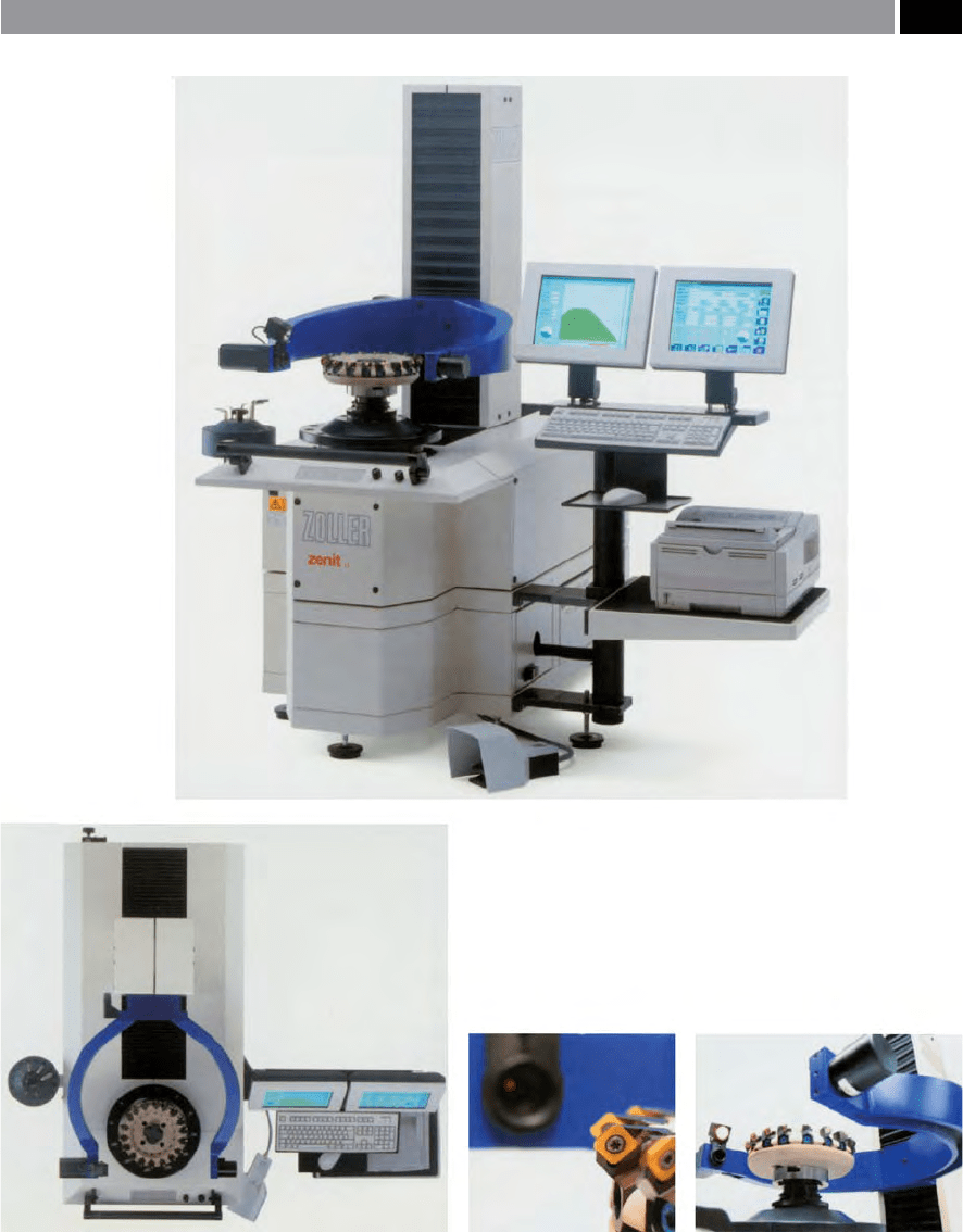
Figure 136. Optical tool presetting machine for sophisticated tool management control. [Courtesy of E. Zoller GmbH & Co. KG].
Modular Tooling and Tool Management 253

Presetting off the Machine Tool
High quality tool measuring equipment has been de-
veloped in order to eliminate the disadvantages of tool
presetting on the machine tool. Presetting machines
(Fig. 136), are usually designed so that they can ac-
curately and precisely locate the toolholder and its
respective cutter, in exactly the same orientation as it
would be situated within the intended machine tool’s
spindle. Once the tooling assembly has been securely
located in the presetter, the tooling’s cutting edge(s),
can then be measured by a range of means, including:
a non-contact optical device, a contacting mechani-
cal indicator, or more ‘primitively’ using some form
of comparator gauges. Hence, by making the neces-
sary tool adjustments whilst the tooling is located in
the presetter, the operator can ensure that when this
inspected tool is nally located in the machine tool, its
respective tool osets will be condently known and
applied to the cutting operation in hand.
By utilising a tool presetter to measure and set tools
o the machine tool, this has been shown to increase
the shop oor productivity by >12% for every machine
using preset tooling. Due to the demands for the high-
est ‘up-time’ possible in the automotive sector, virtu-
ally every production shop employs measured and
preset tools. In fact, studies conducted at manufactur-
ing companies using a presetting tooling facility, have
noted that by utilising a presetter, this has been shown
to save typical workshops >4.52 minutes every time
tools are changed. In the following example on the use
of presetters, it was noted that signicant productivity
time and hence cost-savings can be accrued, these cal-
culations being based upon 20 tool changes per eight-
hour shi, this gave the following savings:
•
Minimum time saved for each tool = 3 minutes,
•
Total minutes saved per shi = 60 minutes,
•
Calculated productivity increase = 12.5%
37
.
37 is 12.5% productivity gain, meant that one hour was saved
for every eight hours of shi operation. Hence, if the facility
was run at the ultimate level of operation, such as in a mass
production automotive machining facility, running a continu-
ous three-shi system, seven days per week. en, a total of
three hours per day, or 21 hours per week would be saved,
which would mean that the amortisation for the capital plant
(i.e. the presetter and its presetting environment), would be
very short indeed.
Signicant tool setting and changing time-savings
are only one major advantage from utilising a sophis-
ticated tool presetter like the one shown in Fig. 136
and its associated screen displays in Fig. 137, other
features include: integrated tool measurement and
inspection and data-storage facilities. Down-loading
this tool oset and other important data through a
DNC-link to each relevant machine tool, making them
a vital part of the overall tool-management system. A
high-quality tool presetting machine can set tools to
‘micron-levels’ of accuracy and precision (i.e. typically
± 2 µ
m), holding these preset levels with condence as
soon as they begin cutting chips – so no ‘trial cuts’
are necessary. Moreover, a range of toolholding ‘back-
ends’ can be accommodated in the machine’s spindle,
by using special-purpose adaptors. e tool presetting
soware guides an operator through the measuring
program and other tool management tasks. Within
the presetter’s computer memory, an operator can
store and retrieve tooling information as necessary,
allowing for repeat setups, or replacement tools to
be speedily and eciently measured and set. On the
presetter shown in Fig. 136, this machine allows typi-
cal tooling screen displays shown in Fig. 137, having
a photo-realistic input screen, which guides the user
t
hrough the measurement and setting program in
easy-to-follow steps. is data is stored for further
use and enables tooling repeatability, with very little
variability, allowing each individual set tool to have
almost identical oset dimensions. is repeatability
ensures that the operator can load the machine tool’s
spindle with condence, allowing for tool-data opti-
misation to be achieved on the machine – when these
tools are operating under batch, or mass production
runs.
For many of today’s presetting machines, they al-
low the operator to inspect the tooling with ‘video-
technology’ (Fig. 137) to assess for tool wear and its
measurement. Flank wear in particular, is oen a good
guide as to the probable life le in the tooling, prior
to a tool change. At a certain level of predetermined
wear land, the tool is deemed to need replacing. Not
only can a presetter be used for presetting tooling
assemblies and for tool wear assessment, it can also
be employed to monitor and inspect incoming tool-
i
ng from suppliers in the ‘as-received condition’ , to
254 Chapter 6
‘Vendor rate’
38
and establish the tooling supplier’s
quality levels – in terms of their tool geometry and in
certain instances, dimensional tolerances.
If a presetting machine’s tool set-up and inspection
capabilities are combined with sophisticated soware,
its overall abilities are considerably enhanced. Here, it
has the potential to perform both tool and component
tracking, together with that of whole tooling assem-
blies within the production facility, whilst operating
as a complete tool management system. With such
a computerised-system in place, it can store data on
individual components and when required, select the
relevant information to assemble a complete tool. is
data availability, can include the overall tooling in-
ventory and the operator can monitor the workshop’s
stock of tools and order replacements, based upon a
‘Just-in-Time (JIT)’ strategy (i.e. see Footnote 17) – by
directly ordering from the tooling suppliers computer-
ised-stocklists. In order to obtain maximum eciency
with the tool presetter, this can be achieved by linking
it with the in-house computer network. Hence, a fully-
integrated presetting machine can exchange data with
the company’s other peripheral-networked computer
systems, enabling tool lists and other relevant infor-
mation for specic production jobs to be down-loaded
directly to the presetter.
Aer the tooling assembly measurements are com-
pleted, the presetter can generate the data in a CNC-
compatible format, then DNC down-load to the des-
ignated machine tool, removing the necessity for the
machine tool setter/operator to input the tooling and
cutting data into the controller, enabling production
to begin as soon as the tools are loaded into the tool
38 ‘Vendor rating’ (VE), is a basic form of ‘Supply-chain man-
agement’ by an organisation and is normally used in purchase
decision-making. In VE, this evaluation process is formalised
to provide a quantitative measurement of ‘Vendor Quality’
(VQ). erefore, VR is primarily meant to impart an overall
rating of a particular vendor for use in: reviewing, compar-
ing and selecting vendors – this procedure being an integral
part of a rigorous purchasing process and in some instances is
utilised instead of acceptance sampling.
NB Oen, it will be dicult to simply create a single numeri-
cal quality/rating score, due to the dierent factors which must
be taken into account. Some form of ‘weighted-point’ VR plan,
based upon the companies prioritised needs from individual
suppliers, this allows for comparisons between dierent com-
petitive suppliers.
Figure 137. Typical cutter screen displays from an optical
tool presetting machine. [Courtesy of E. Zoller GmbH & Co. KG]
.
Modular Tooling and Tool Management 255

storage magazine. e latest tool presetting machines
equipped with a full suite of tool management features
and functions, can play a big role in improving shop:
productivity/component quality, tool life, inventory
control, whilst minimising down-time, reducing com-
ponent cycle times and part scrappage.
Mounting and Adjusting Milling Cutters
Possibly the most crucial cutter body to correctly
mount and adjust, for the individual cutting inserts,
is that of a side-and-face cutter (Fig. 138). e reason
why it is important to set the cutter assembly up cor-
rectly, is that invariably the width of the slot in the ma-
chined workpiece is identical to that of the respective
rotating face widths of the cutting edges. Moreover,
whole cutter assembly must ‘run true’ as it rotates on its
arbor
39
– with no discernible ‘wobble’ – as this eective
‘wobbling’ will inuence the machined slot geometry.
At its most extreme, some of these special-purpose
slotting cutters can be >2 tonnes in weight and larger
t
han 1.5 m in diameter, having segmented cartridges
that are precisely and accurately tted onto the periph-
e
ry of the cutter body. As a general ‘rule of thumb’ ,
most of these types of slotting cutters are used to ma-
chine component features to a depth of four times
their slot width
40
. If a deeper slot is required, then the
cutter has to be ‘optimised’ in some way. Perhaps by
using a smaller width cutter than that required for the
component’s slot width and, if possible, cutting each
slot face separately and eventually taking it to the de-
sired width/depth – arbor interference permitting.
Mounting cutting inserts in the case of the stag-
gered-toothed side-and-face cutter body shown in Fig.
138, is relatively straight forward, due to the lateral
adjustment available by the splined cartridge seatings.
Here, it is important to ensure that the insert seat is
thoroughly cleaned prior to commencing tment.
Moreover, ensuring that the contact against the bot-
39 ‘Arbor’ , is the workshop term used for the extension from the
machine tool’s spindle that the slotting-type cutter is located
and driven from. It can be cantilevered – termed a ‘stub-ar-
bor’ , or supported at its free-end, by an arbor-support – nor-
mally tted with adjustable and suitable matched-bearing di-
ameters.
40 When full slotting, using a side-and-face milling cutter at 40%
of the maximum radial cutting depth, a typical feed per tooth
w
ould be around 0.25 mm tooth
–1
.
tom face of the seat occurs, prior to tightening the set
screw – normally to a nal torque value of 5 Nm (i.e.
illustrated in Fig. 138b). Each set screw should be lu-
bricated with the recommended lubricant before re-
use. In order to ensure that each cutting insert runs
true, the slotting cutter, or face mill assembly, should
be correctly mounted – in the former case, onto the ar-
bor, the latter into the correct spindle nose taper – be-
ing held on a suitable presetting machine. e whole
assembly is then rotated to ensure that each cutting in-
sert is both radially and axially positioned, thereby en-
suring that no edges ‘stand-proud’ of each other and at
the same time conrming that no discernible ‘wobble’
in the rotating assembly occurs (i.e see the deep-slot-
ting cutter, held in a stub arbor with support, allowing
the whole tooling assembly to be rotated and each cut-
ting insert to be inspected/measured, in Fig. 139).
Although cutter keyways are not strictly-speaking a
mounting problem, the subject does need to addressed,
as if the cutter’s diameter and its associated driving
keys are not considered, this will limit the overall mill-
ing performance of the cutter. With most slotting, and
side-and-face cutters tted to arbors, they normally
require a keyway/key for rotational driving purposes
for the whole cutter assembly. Usually cutters that
are <φ1
25 mm with insert sizes ranging between 6 to
8 mm, then one key will suce, but cutters >φ1
40 mm
with insert sizes of between 1
1 to 14 mm, they would
frequently need two keyways
41
.
Cutter diameter and driving key limitations, are de-
termined by the cutter’s bore and its connected key-
way, together with the D
OC
being limited by several
factors: the arbor OD, its mechanical strength, plus
any deformation of the driving key(s). For vertical
slotting applications, mounting the cutter on an large
diameter arbor with the minimum of overhang is de-
sirable. If the feed per tooth can be reduced – assum-
ing component cycle-times will allow – then this will
reduce the tendency of key deformation during mill-
ing. Milling calculations and key strength, can be ob-
tained from the following expressions and are valid for
new cutting inserts:
41 Keyway positioning for two keys – is usually given by the dis-
tance between them as: 180° minus half the peripheral pitch
of adjacent cutting inserts – as shown in the diagrammatic
sketch in Fig. 138a.
256 Chapter 6
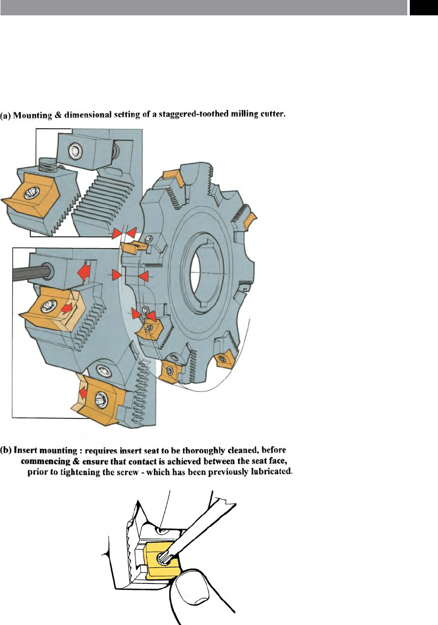
Figure 138. The correct mounting
and setting of a cutting inserts in a
staggered-toothed side-and-face cutter
body. [Courtesy of Sandvik Coromant]
.
Torque (T) = P [kW]/n [rpm] × 60,000/2π [Nm]
Force (F) = T/d
[mm] × 1,000 [N]
Shear [keyway] stress (τ) = F/
area = F/A × E [N mm
–2
].
NB As the cutting inserts wear, the above values will
increase by approximately 30%, therefore, it is usual
to add a ‘safety factor’ to the key(s) material shear
strength, by multiplying this value by 1.5.
Modular Tooling and Tool Management 257
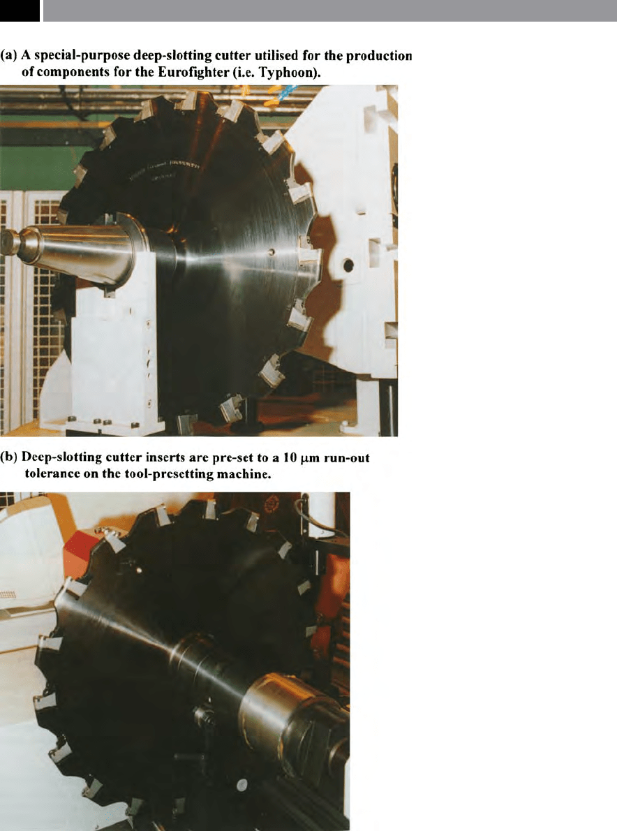
Figure 139. Cutting inserts for large diameter cutters require pre-setting to mini-
mise any run-out. [Courtesy of Starrag Machine Tool Co. and Sandvik Coromant]
.
258 Chapter 6

If special-purpose applications are required, such as
when form milling the ubiquitous ‘Vee-and-Flat’ con-
guration for an conventional engine-/centre-lathe
bed, ‘gangs’
42
of: side-and-face, angled- and helical-cut-
ters are deployed to form and generate these slideways.
Here, it is important to ensure that when presetting
the cutters on the tool presetter, that the whole cut-
ter assembly is held in the exact manner that they will
be utilised when ‘gang-milling’. is ‘gang-milling’ set-
up, allows their dimensions and forms to be inspected/
measured, while slowly rotating the whole assembly. If
two ‘
helical cutters’
43
are utilised in a ‘gang-milling’ op-
eration, then their helices should be of the same pitch,
but of dierent ‘hands’ (i.e. le-ward and right-ward
respectively), as this arrangement will balance-out any
end-thrust due to opposite cutter helices.
Setting up ‘Long-edge milling cutters’ – these are
sometimes termed ‘Porcupine cutters’ (i.e. see Fig.
124 – centre), which are normally required for the
heavier and longer cutting applications, is quite a com-
plex presetting process. As the individual cutting in-
serts must be slowly rotated to ensure that axial and ra-
dial run-out values are kept to a minimum. Otherwise
those inserts ‘standing-proud’ of the remainder will
suer from greater wear rates, thereby prematurely re-
ducing the cutter’s eective life quite signicantly while
milling an unwanted step into the machined sidewall.
On standard face mills, ‘face run-out’ can be as high
as >50 µm, so when close tolerances and good milled
surface texture is mandatory, then extreme care must
42 ‘Gang-milling’ , is a complex forming process utilising two,
or more milling cutters adjacent to one another. So, a side-
and-face cutter, located directly together with a helical cutter,
represents a ‘gang’ in its simplest form. is ‘gang’ of cutters, is
normally permanently mounted together for re-grinding and
tool presetting – this is assuming that the cutting edges are
not made-up from a series of strategically-positions indexable
inserts (see Fig. 76).
NB ‘Straddle milling’ , should not be confused with ‘gang-
milling’ , as here, it is normal to use two side-and-face cutters
with spacing collars between them – of a specic and known
dimensional size. erefore, the cutters ‘straddle’ the part –
hence its name – while they machine two faces at the required
distance apart in one pass along the workpiece.
43 ‘Helical cutters’ ,
are sometimes known as ‘Slab-mills’ , hav-
ing either a le-, or right-hand helix, which ensures that the
length of cut and its shearing mechanism are reduced by a
‘quick-helix’ , which is necessary for the milling of more duc-
tile materials.
be taken when presetting such tooling assemblies. In
order to assist the presetting of such tooling on some
face mills, ‘barrel screws’ allow ne adjustment to the
cutting insert (Fig. 140a). Such ‘barrel screw’ designs
are quite simply-designed, but surprising eective in
both adjusting and retaining the cutting inserts, the
following remarks explain how they are designed and
their method of operation. ‘Barrel screws’ (Fig. 140a),
are hardened to resist deformation and have a black-
oxide nish to minimise corrosion. To prevent them
from shiing during a face milling operation, a nylon
pellet is embedded in the thread of the ‘barrel screw’.
Right-hand cutting inserts use le-hand ‘barrel screws’
and vice versa, as this counter-acting rotation keeps the
insert locked rmly in its pocket. e mating surface
of a ‘barrel screw’ is reamed produce a minimum con-
tact of 120° occurs, which ensures accuracy and preci-
sion, while minimising wear. e ‘barrel screw’ hole is
o-set toward the reamed surface, to provide positive
contact with the mating surface throughout the range
of adjustment of this screw. It should be noted, that
these ‘barrel screws’ cannot adjust the eective ‘gauge-
length’ of the tooling, as the amount of adjustment is
limited by the position of the cutting insert’s clamping
screw.
e face-milling cutting inserts shown in Fig. 140a
are tangentially-mounted, oering considerable sup-
port and additional strength to the cutting edge. When
presetting the face mill’s cutting edges when the cut-
t
er body is equipped with ‘barrel screws’ , the following
procedure should be adopted:
•
To adjust the insert outward – leave the cutting in-
sert tight and simply turn the ‘barrel screw’ to move
the insert to the desired setting.
NB A
djustment to the cutting insert’s position,
should only be made in one direction only.
•
To adjust the insert inward – loosen both the cut-
ting insert and ‘barrel screw’ , push the insert in-
ward, then tighten the insert’s screw and adjust out
again to the desired position.
In Fig. 140b, the simple ‘ow-chart’ highlights why it is
important to keep any face milling cutter insert’s run-
out to a minimum. If the run-out o
f both the minor
and peripheral cutting edges is large, then this can
create several undesirable problems for the tooling as-
sembly, including:
•
Poor surface nish – if a cutting insert ‘stands-
proud’ of the others in the face mill, then it will cut
Modular Tooling and Tool Management 259
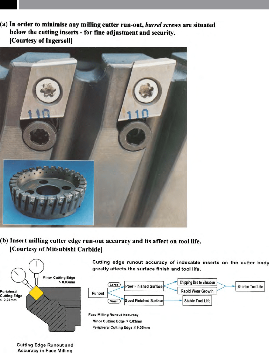
Figure 140. Cutting inserts need to be precisely and accurately seated in their respective pockets of the cutter body, to eliminate
potential run-out
.
260 Chapter 6

in a similar fashion to that of a y-cutter, creating a
periodically scored surface – aer each cutter revo-
lution – degenerating the milled surface texture,
•
Chipping due to vibration – as all of the inserts are
not set the same, then the most prominent one will
take the largest cuts on both the minor and periph-
eral cutting edges, causing shock loading as the cut
is engaged, thereby increasing cutter vibration and
potential thermal eects
44
creating the likelihood of
chipping here on the most exposed cutting inserts,
•
Rapid growth of wear – because of a prominently
set and poorly positioned cutting insert in relation
to the others in the cutter body, it will absorb the
greatest cutting loads, which will lead to shortened
tool life, this being exacerbated by pronounced vi-
brational tendencies, resulting from unbalanced
cutting forces and torque.
NB A
ll of these factors will contribute to a short-
ened cutter life.
Conversely, if the face milling cutter’s insert run-out is
small, then a good surface nish and stable and predict-
able tool life will result.
Mounting and Adjusting Single-Blade Reamers
e cutting head of a single-blade reamer was previ-
ously illustrated in Fig. 74a. e replaceable blade
is positioned longitudinally by a blade end stop and
44 ‘ermal fatigue’ , can be present when cutting is interrupted
– as is the case for milling with a prominently exposed ce-
mented carbide cutting insert. Numerous cracks are oen ob-
served at 90° to the cutting edge and are oen termed: ‘Comb-
cracks’ – due to their visual appearance to that of a typical
hair-comb. ese cracks, are the result of alternating expan-
sion and contraction of the surface layers as the cutting edge
is heated during cutting, then cooled by conduction into its
body during intervals between cuts. is very fast alternating
heating and cooling cycle, develops the cracks normally from
the hottest region of the rake face – this being some distance
from the cutting edge, which tends to spread across this edge
and down the insert’s ank face. Once these cracks become
quite numerous, they can join up and promote partial tool
edging to break away – creating cutting edge chipping.
NB Today, many cemented carbide tooling manufacturers
use structures and compositions that are less sensitive to ther-
mal fatigue, moreover, coatings also play a signicant role in
reducing thermal fatigue eects, when milling.
diametrically adjusted using the front and rear adjust-
ing screws. e blade is micro-adjustable over a lim-
ited range of radial movement and can be preset in
a special-purpose setting xture (Fig. 141a and c), to
ream the desired diameter that the tool can then con-
sistently produce. is reaming blade normally has a
back taper o
f: between 0.01 to 0.02 mm over a linear
distance of between 10 to 25 mm, respectively – when
positioned in the pre-setting xture (Fig. 141b shows a
three-guide pad designed single-blade reamer). A fea-
ture of the blade’s adjustment, is that it can be reset to
compensate for any subsequent blade wear. A clamp,
plus two clamping screws securely holds the blade in
place, with the wedge-type clamp providing support
along the entire blade length (Fig 74a). In the case
of the single-bladed reamer design illustrated in Fig.
74a, the blade is located and positioned in the ream-
ing head at an 12° positive rake angle. For this type of
reamer design, additional standard blades can be t-
ted, oering both 6° and 0° rake angles.
Taper reaming setting can be achieved by mounting
the taper reamer (i.e a taper reamer is shown ream-
ing a component feature in Fig 73b), into the spe-
cial-purpose setting xture (Fig. 141c). At least two
dial-, or electronic-indicators are positioned along the
blade’s length, then adjusted so that a very light pres-
sure is applied to the cutting edge of the blade – to
prevent it from inadvertently chipping. With the
b
lade ‘semi-clamped’ , adjustment is made so that its
is parallel along its length – relative to the tapered
g
uide pads. Once the blade has been ‘fully clamped’ ,
adjustment occurs to position it higher than its guide
p
ads’ diameter, by between 10 to 20 µm – all along the
blade’s length, which achieves an accurate setting, but
this setting will depend on both the workpiece mate-
rial and the prevailing machining conditions
45
.
6.5.5 Tool Store and its Presetting
Facility – a Typical System
In the worst case scenario, for many of the ‘old-style’
traditional workshops, the tools are as oen as not
45 Taper reamers – typical machining details: Cutting speed 4 to
20 m min
–1
(Stainless steel 2 to 6 m min
–1
), Feed 0.2 to 0.8 mm
rev
–1
, Machining allowance 0.2 mm and up to 0.5 mm – for
large taper reamers, plus Coolant soluble oil @ 10% dilution.
Modular Tooling and Tool Management 261