Труды Всемирного конгресса Международного общества солнечной энергии - 2007. Том 2
Подождите немного. Документ загружается.

Proceedings of ISES Solar World Congress 2007: Solar Energy and Human Settlement
632
I
tt
aa
ai
−
+=
21
η (1)
where the coefficients that best correlate the data were
found equal to : α
1
= 0.33, α
2
= -2.06 for the data of Fig. 6a,
α
1
= 0.38, α
2
= -1.90 for those of Fig. 6b respectively.
(a)
(b)
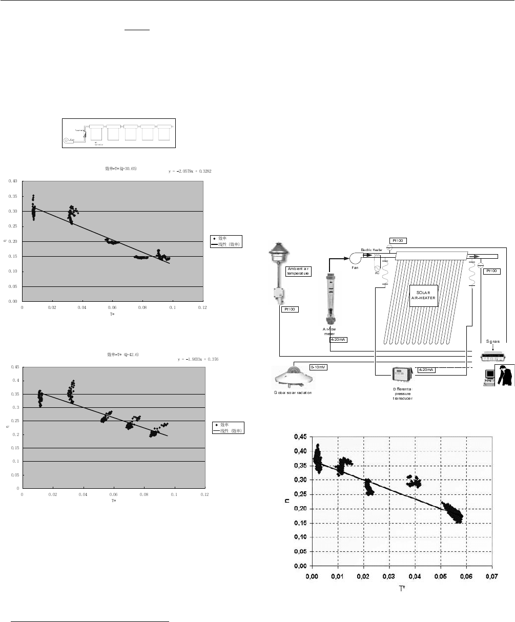
Fig. 6: Instantaneous efficiency curve from measurements
on an array of collectors, based on the experimental
data of SEL-CAS for a flow rate equal to (a) 30.6 m
3
,
(b) 42.6 m
3
.
4. SESL/NCSR “D” MEASUREMENTS
The setup developed by SESL/NCSR “D” for the
experimental determination of the instantaneous efficiency
curve of the collector is depicted inf Fig. 7a. At SEL/CAS,
by using an array of collectors in series, each of which was
operating at a different inlet temperature, it was possible to
derive the data with a series of measurements at each flow
rate. In the case when a single collector is available,
preheating of air at different temperatures has to be
provided, at a constant flow rate. Therefore, for the
SESL/NCSR “D” measurements, initially air at ambient
inlet temperature was supplied to the collector and this was
later increased to mean inlet values of 22ć, 40ć, 55ć
and 70ćsuccessively. For each of these values, measure-
ments were taken for one day under constant flow rate and
by using tracking. For the curve estimation, only data over
periods with average insolation of at least 800 W/m
2
were
considered and which deviated from the mean value by
(a)
(b)
Fig. 7: (a) Experimental setup for the investigation at
SESL/NCSR “D” and (b) efficiency curve from
measurements with at a flow rate of 33 m
3
/h.

3 SOLAR COLLECTOR TECHNOLOGIES AND SYSTEMS
633
±50 W/m
2
. Thus, the curve shown in Fig. 7(b) was derived,
corresponding to a flow rate of 33 m
3
/h. From the data in
this figure, the correlating line of the form of Eq. (1) for the
efficiency yielded : α
1
= 0.367, α
2
= -3.353. The efficiency
was computed from the expression :
AG
TTCm
ioutp
)( −
=
η
(2)
where
m
is the overall mass flow rate, C
p
the specific
heat of air, Τ
i
και Τ
out
the collector inlet-outlet
temperatures, G the insolation (W/m
2
), whereas A is the
aperture surface area of the collector, taken as the
projection of the absorbing surface of each tube on a
longitudinal plane, times the number of the tubes. The
correlation coefficient of the line in Fig. 7b is R
2
= 0.92. As
may be observed, the maximum values of the efficiency η
0
arising for Τ* = 0 measured by the two laboratories lie very
close to one another (coefficients of Eq. (1)), however the
slope of the correlating line is different. This fact may be
attributed to differences in external conditions, such as
ambient temperature, wind speed etc.
5.
CONCLUSIONS
Numerical simulation of flow and heat transfer has been
shown to be a very useful tool in the analysis and
understanding of the energy behavior also in the case of
solar collectors with evacuated tubes, by revealing their
specific features in terms of the flow and temperature fields
that develop within them.
The flow phenomena that develop inside evacuated tubes,
which are characterized by large length/diameter ratios, are
complex and further investigation is required, particularly
on the boundary conditions imposed and the influence of
natural convection.
The experimental investigation of solar collectors with
evacuated tubes and air as the working medium has confirmed
the fact that these are quite promising and offer an
exploitation potential in applications were hot air is
required, such as space heating and/or dehumidification,
drying of agricultural products etc.
6.
ACKNOWLEDGMENTS
The present work was supported by the General Secretariat
for Research & Technology of the Greek Ministry of
Development and the Ministry of Science and Technology
of Peoples’ Republic of China, in the framework of their
bilateral S & T Cooperation Program. The authors would
also like to thank the companies Cicero Hellas (Calpak)
from Greece and Himin Solar Energy from China for
providing the equipment for the collector measurements.
7.
REFERENCES
(1) Rabl A., “Collector Concepts and Designs” in Solar
Collectors, Energy Storage, and Materials, F. de Winter
(ed.), MIT Press, 1990.
(2) Kakaç S., Shah R.K. and Aung W., “Handbook of
single-phase convective heat transfer”, J. Wiley & Sons,
Inc., New York, 1987.
(3) Cabanillas R.E., Estrada C.A. and Avila F., “A device
for measuring the angular distribution of incident
radiation on tubular solar collectors”, Renewable
Energy, vol. 6(7), pp. 843-847, 1995.
(4) Heaton H.S, Reynolds W.C. and Kays W.M., “Heat
transfer in annular passages. Simultaneous
development of velocity and temperature fields in
laminar flow”, Int. J. of Heat and Mass Transfer, v.
7(7), pp. 763-781, 1964.
(5) Shah R.K. and London A.L., “Laminar flow forced
convection in ducts”, Adv. in Heat Transfer, Suppl. 1,
T.F. Irvine Jr. & J.P. Hartnett (eds.), Academic Press,
New York,1978.
(6) Morrison G.L., Budihardjo I. and Behnia Μ.,
“Water-in-glass evacuated tube solar water heaters”,
Solar Energy, vol. 76(1-3), pp. 135-140, 2004.

SIDE-BY-SIDE TESTS OF DIFFERENTLY DESIGNED EVACUATED
TUBULAR COLLECTORS
Jianhua Fan, Janne Dragsted, Simon Furbo
Department of Civil Engineering, Technical University of Denmark
Brovej, Building 118, DK-2800 Kgs Lyngby, Denmark
jif@byg.dtu.dk
ABSTRACT
Six differently designed evacuated tubular collectors, ETCs,
utilizing solar radiation from all directions, have been
investigated experimentally. The evacuated tubular solar
collectors investigated include one SLL all-glass ETC from
Tshinghua Solar Co., four heat pipe ETCs from Sunda
Technolgoy Co. and one all-glass ETC with heat pipe from
Exoheat AB.
The collectors have been investigated side-by-side in an
outdoor test facility for a long period. During the
measurements, the operating conditions – such as weather
conditions, inlet and mean solar collector fluid
temperatures have been the same. Thus a direct
performance comparison is possible.
The results of the measurements will be presented in this
paper. Among other things, the influence on the thermal
performance of the absorber design will be explained.
Further, it will be illustrated how the thermal performances
of the different collector types depend on the operating
conditions and the time of the year and the collector
performances will be compared.
1. INTRODUCTION
The world market for solar thermal collectors has expanded
significantly in the last decades. Evacuated tubular
collector is one of the most commonly used collector types
in the market. In recent years the evacuated tubular
collectors have gained an increasing share of the market.
On the world largest solar thermal market, China,
evacuated tubular collectors have increased the market
share from 30% in 1998 up to 84% in 2002 (1), (2). In
Germany, the market share of evacuated tubular collectors
is doubled to almost 20% in year 2001 alone due to a
nationwide subsidy program. Coming with the booming
market, there is a large number of collector manufactures
providing evacuated tubular collectors with a variety of
designs such as all-glass, heat pipe, all-glass with heat pipe,
with and without reflectors.
In high latitude regions like the Arctic, the advantages of
evacuated tubular collectors are not only low heat loss and
high efficiency, but also the ability to utilize solar radiation
from all directions due to the large variation of the solar
azimuth. The aim of this paper is to investigate thermal
performances of differently designed evacuated tubular
collectors utilizing solar radiation from all directions.
Side-by-side tests of six differently designed evacuated
solar collectors were carried out in a period from February
6, 2006 to May 6, 2007. The thermal performances of the
differently designed evacuated tubular collectors are
compared. Based on the observations from the
measurement, it will be elucidated how the collector
performance is influenced by the solar collector designs
and the weather and operation conditions.
3 SOLAR COLLECTOR TECHNOLOGIES AND SYSTEMS
635
2. EXPERIMENTAL METHOD AND THE INVESTI-
GATED ETCS
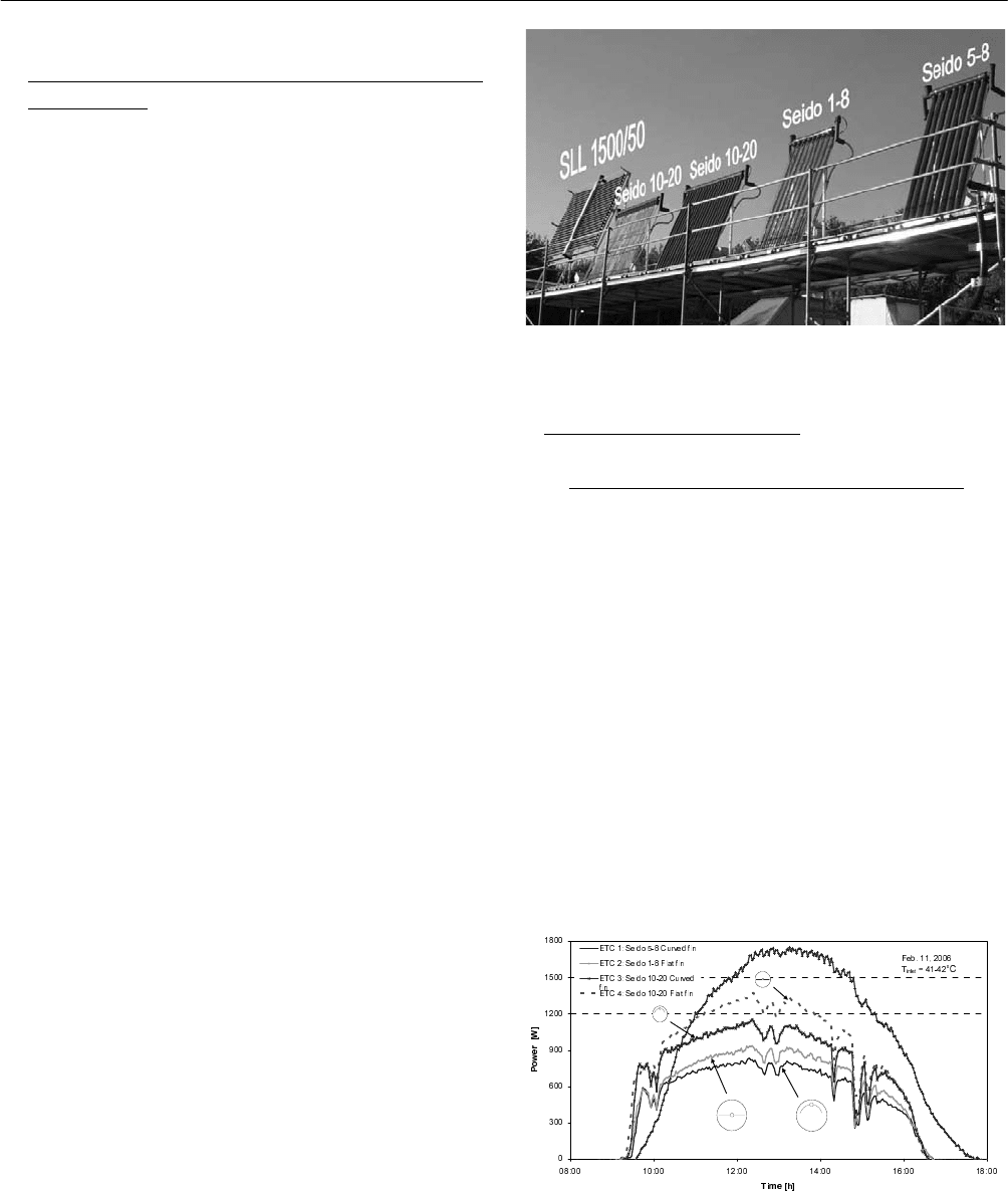
The side-by-side tests were carried out in a test facility at
the Technical University of Denmark, latitude 56°N, see
Figure 1. On the test platform, five collectors can be tested
under the same conditions at a time. The collectors are
directly facing south and have a tilt angle of 67° which is
suitable for typical operation conditions in the Arctic. A
glycol/water mixture of 41% by weight is used as the solar
collector fluid. The fluid flow rate through each of the
collectors is measured by a flow meter type Brunata
HGQ1-R0. The inlet and outlet temperatures of the
collector are measured by thermal couples, type TT. The
difference between the outlet and inlet temperature is
measured by a thermal pile. The five collectors are parallel
connected to a temperature control unit. A pump is used to
circulate the solar collector fluid so that the inlet
temperatures to the collectors are the same. The flow rates
through the collectors are adjusted in such a way that the
average temperatures of the collector fluids in the collectors
are approximately the same during the test. The accuracy of
the absolute temperature measurement and temperature
difference measurement is 0.5 K and 0.1K, respectively.
The accuracy of the flow rate measurement is estimated to
be 1.5%. The measurement data are monitored and logged
every two minutes by LabView.
The measurements were carried out for test periods with
three mean collector fluid temperature levels: 43-45°C,
63-65°C and 76-78°C.
The weather data are measured at the same time in a
climate station located on the roof of a building close to the
test platform. The total and diffuse solar irradiance on
horizontal surface and ambient air temperature are
measured.
The evacuated tubular solar collectors investigated include
one SLL all-glass ETC from Tshinghua Solar Co., four heat
pipe ETCs from Sunda Technolgoy Co. and one all-glass
ETC with heat pipe from Exoheat AB. The fins in the heat
pipe ETCs from Sunda are all coated with selective coating
on both sides in order to utilize solar radiation from all
directions. Detailed information of the tested collectors is
listed in Table 1.
Fig. 1: The side by side test facility.
3. RESULTS AND DISCUSSION
3.1 Influence of Weather and Operational Conditions
Collector performances under different weather conditions
are compared. Figure 2 and 3 show collector performances
in a typical sunny day in winter and summer respectively.
The heat pipe ETCs 1-4 have a jump in collector power in
the morning. A possible explanation of the behavior is that
the heat pipe will not work in the morning until its
temperature increases to a temperature higher than the
lowest evaporation temperature of the working fluid in the
heat pipe and that the upper part of the tubes are heating to
a high temperature before the lower part of the tubes are
heated to the lowest evaporation temperature. This behavior
is caused by shadows in the morning. The all-glass ETC 5
on the other hand starts up slowly and stops almost 1 hour
later than the heat pipe collectors. This can be explained by
Fig. 2: Comparison of collector performance in a winter
day.
Proceedings of ISES Solar World Congress 2007: Solar Energy and Human Settlement
636
its large thermal capacity since a large quantity of collector
fluid is stored in the glass tubes. The heat pipe ETCs with
flat fins perform better than the ETCs with curved fins in
winter, while the ETCs with curved fins and with flat fins
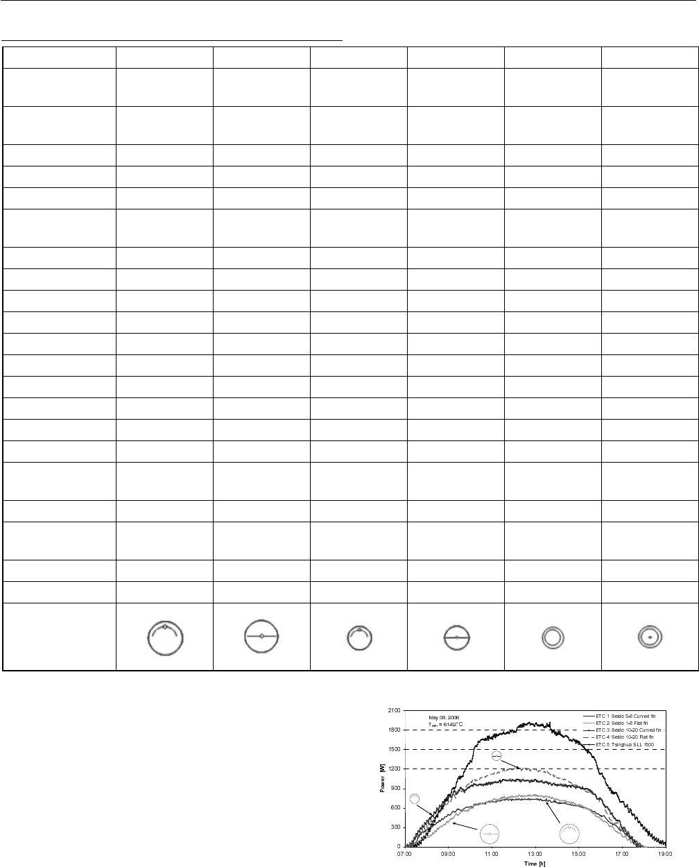
almost perform the same in summer. As can be seen from
Fig. 3, the ETCs with curved fins perform better in morning
and in afternoon while the ETCs with flat fins perform
better in the rest of the day.
Fig. 3: Comparison of collector performance in a summer day.
TABLE 1: DATA SHEET OF THE TESTED COLLECTORS
ETC no. 1 2 3 4 5 6
Collector type Seido 5-8 Seido 1-8
Seido 10-20
with curved fin
Seido 10-20
with flat fin
SLL 1500 VA1858
Manufactures
Sunda
Technology Ltd
Sunda
Technology Ltd
Sunda
Technology Ltd
Sunda
Technology Ltd
Tsinghua Solar
Ltd
ExoHeat AB
Number of tubes 8 8 20 20 50 24
Tube diameter 100 mm 100 mm 70 mm 70 mm 47 mm 58 mm
Tube length 2000 mm 2000 mm 1750 mm 1750 mm 1500 mm 1800 mm
Tube centre
distance
111-120 mm 111-120 mm 86-93 mm 86-93 mm 72-75 mm 79-84 mm
Transparent area 1.54 m
2
1.54 m
2
2.36 m
2
2.36 m
2
3.30 m
2
2.45 m
2
Collector height 2.16 m 2.16 m 1.90 m 1.90 m 2.00 m 1.97 m
Collector width 0.96 m 0.96 m 1.86 m 1.86 m 3.20 m 1.99 m
Gross area 2.07 m
2
2.07 m
2
3.53 m
2
3.53 m
2
6.40 m
2
3.92 m
2
Absorber area 3.66 m² 2.80 m² 6.60 m² 4.00 m² 8.71 m² 6.17 m²
Absorber material Aluminum Aluminum Aluminum Aluminum Glass Glass
Absorber thickness 0.47 mm 0.47 mm 0.6 mm 0.6 mm - -
Selective coating Aluminum Ni Aluminum Ni Aluminum Ni Aluminum Ni Aluminum Ni Aluminum Ni
Absorptance 0.92 0.92 0.92 0.92 0.90 0.92
Emittance 0.08 0.08 0.08 0.08 0.08 0.08
Glass
Borosilicate
glass
Borosilicate
glass
Borosilicate
glass
Borosilicate
glass
Borosilicate
glass
Borosilicate
glass
Glass thickness 2.5 mm 2.5 mm 1.7 mm 1.7 mm 1.6 mm 1.6 mm
Transmittance at
incidence angle 0°
0.91 0.91 0.91 0.91 0.91 0.91
Vacuum < 10
-3
Pa < 10
-3
Pa < 10
-3
Pa < 10
-3
Pa <5×10
-2
Pa <5×10
-3
Pa
Manifold diameter 28 mm 28 mm 38 mm 38 mm 45 mm 38 mm
Symbol
3 SOLAR COLLECTOR TECHNOLOGIES AND SYSTEMS
637
3.2 Long-Term Collector Thermal Performance
Long-term measurements were carried out in the period
from February 6, 2006 to May 6, 2007. The experiment can
be divided into two phases:
Phase 1: February 6 - June 25, 2006
Collector Seido 5-8, Seido 1-8, Seido 10-20 with curved fin
and Seido 10-20 with flat fin and SLL 1500/50 were tested
side by side.
Phase 2: July 20, 2006 – May 6, 2007
Collector Seido 1-8, Seido 10-20 with flat fin and VA1858
were tested side by side.
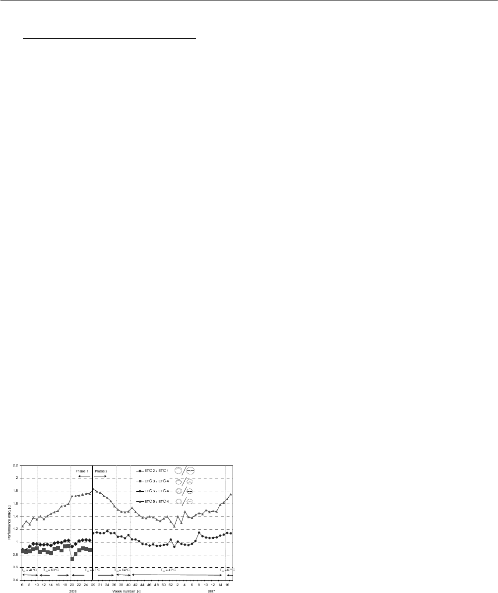
Fig. 4 shows weekly performance ratios of the differently
designed collectors during the whole test period. The
performance ratio is defined as the ratio between the
thermal performance of the collector in question and the
thermal performance of the Seido 1-8 or Seido 10-20 with
flat fin. It can be seen that the all-glass ETC 5 performs
relatively good in summer compared to the winter. The
performance ratio of ETC 5 to ETC 4 is insignificantly
influenced by the mean collector fluid temperature.
Concerning the heat pipe ETCs, the collectors with curved
fins tends to perform better in summer than the collectors
with flat fins. The reason is that the curved fin in a good
way can utilize solar radiation in the morning and in the
afternoon while the incidence angle of solar irradiance is
high. With the increase of mean collector fluid temperature,
the collector with flat fin tends to perform better than the
collector with the curved fin. The reason is most likely due
to the relatively lower heat loss from the collector with flat
Fig. 4: Comparison of thermal performance of differently
designed collectors.
fin compared with the collector with curved fin. It can be
seen from measurement of Phase 1 that the performance of
ETC 3 is worse than the performance of ETC 4.
As can be seen from Phase 2, the performance of ETC 6 is
slightly better than ETC 4, especially in summer with large
variation of the solar azimuth, while in winter ETC 4
performs better than ETC 6. The performance ratio for ETC
6 is not influenced by the temperature level of the solar
collector fluid.
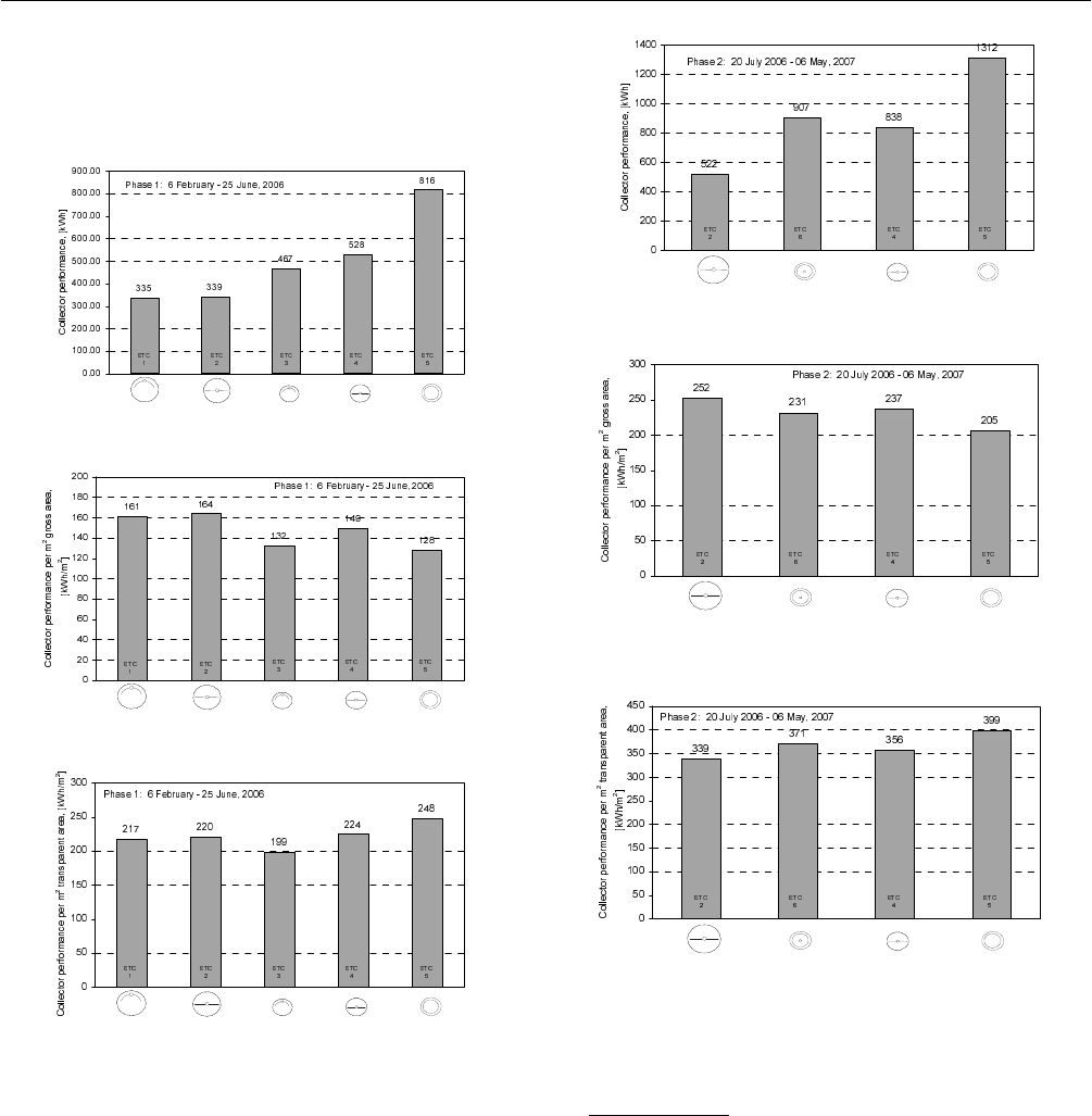
The collector performance in phase 1 is summarized in Fig.
5. Concerning the four heat pipe evacuated tubular
collectors (type 1-4), the collectors with flat fins perform
relatively better than the collectors with curved fins. For a
collector with a tube diameter of 70 mm, type 3 and 4, there
is an increase of 13% of collector performance if a flat fin
is used instead of a curved fin, while for a collector with a
tube diameter of 100 mm, the extra thermal performance
for the collector compared to the collector with curved fin
is quite small, only approximately 1%. ETC 5 has the
largest energy output among the collectors due to its larger
collector area.
The ratio of tube diameter to tube center distance is an
important factor of the collector design which will
significantly influence the collector performance. Assuming
a constant number of tubes, the lower the ratio, the larger
the total collector area, therefore the lower the collector
performance per m
2
gross area will be. On the other hand,
the lower the ratio and the farther the distance between the
tubes will be, the less the shades from adjacent tubes will
be, therefore the higher the collector performance per m
2
transparent area will be. The ratios are 83-90% for collector
1 and 2, 75-81% for collector 3 and 4 and 63-65% for
collector 5, respectively.
Figure 5 (b) and (c) present collector performances per m
2
gross area and collector performances per m
2
transparent
area, respectively. Since collector type 5 has the lowest
tube diameter to tube centre distance ratio, it has the lowest
energy output of 128 kWh per m
2
gross area and the largest
energy output of 248 kWh per m
2
transparent area. Since
Proceedings of ISES Solar World Congress 2007: Solar Energy and Human Settlement
638
collector types 1 and 2 have the highest tube diameter to
centre distance ratio, they have the best performance per m
2
gross area as expected.
(a)
(b)
(c)
Fig. 5: Collector performance in Phase 1.
Figure 6 shows collector performance in Phase 2. Collector
6 has a tube diameter to centre distance ratio of 69-73%
between the ratios for collector 5 and 4, so the performance
per m
2
transparent area, 371 kWh, is smaller than that of
collector 5 and higher than that of collector 4.
(a)
(b)
(c)
Fig. 6: Collector performance in Phase 2.
4. CONCLUSION
Side by side tests of six differently designed evacuated
tubular collectors were carried out in an outdoor test
facility. The observations from the measurements show
that the all-glass ETC and the all-glass ETC with heat pipe

3 SOLAR COLLECTOR TECHNOLOGIES AND SYSTEMS
639
performrelatively better in summer than the rest of the
year. This behavior is not influenced by the mean
collector fluid temperature. The heat pipe ETC with flat
fin performs better than the ETC with curved fin in most
of the test period and the superiority will increase in
winter periods and in periods high mean solar collector
fluid temperature.
5.
ACKNOWLEDGMENTS
This study has been financed by VILLUM KANN RAS-
MUSSEN FOUNDATION.
6. REFERENCES
(1) Z. Q. Yin, “Development of Solar Thermal Systems in
China”, Solar Energy Materials & Solar Cells, 86, 2005,
pp. 427-442.
(2) W. Weiss, I. Bergmann, G. Faninger, “Solar Heating
Worldwide. Markets and Contributions to the Energy
Supply 2001”. IEA Solar Heating & Cooling
Programme, 2004.

SOLAR THERMAL COLLECTORS IN POLYMERIC MATERIALS: A NOVEL APPROACH
TOWARDS HIGHER OPERATING TEMPERATURES
João Farinha Mendes, Pedro Horta, Maria João Carvalho
INETI – Instituto Nacional de Engenharia Tecnologia e
Inovação, IP
Estrada do Paço do Lumiar, 22
1649-038 Lisboa, Portugal
farinha.mendes @ineti.pt
Paulo Silva
PLASDAN – Máquinas para Plásticos, Lda
Rua 52, Nr. 44, Trutas,
2430-520 Marinha Grande, Portugal
ABSTRACT
The increasing demand for low temperature solar thermal
collectors, especially for hot water production purposes in
dwellings, swimming pools, hotels or industry, has lead to
the possibility of high scale production, with leading
manufacturers presenting yearly productions of hundreds of
thousands of square meters.
In such conditions, the use of polymeric materials in the
manufacturing of solar collectors acquires particular
interest, opening a full scope of opportunities for lower
production costs, by means of cheaper materials or simpler
manufacturing operations.
Yet, the use of low cost materials limits the maximum
operating temperatures estimated for the collectors
(stagnation) to values around 120 ºC, easily attainable by
any simple glazed solar collector.
Higher performances, leading to higher stagnation
temperatures as those observed for regular metal-based
solar thermal collectors, would require high temperature
polymers, at a much higher cost.
The present paper addresses the manufacturing of a high
performance solar thermal collector based in polymeric
materials and includes a base thermal study, highlighting
the different possibilities to be followed in the production
of a polymeric collector, as well as a description of
different temperature control strategies.
1. INTRODUCTION
The use of polymeric materials in the construction of solar
collectors has been pursued for long, given the obvious
advantages it presents from both the manufacturing and
economical points of view.
The maximum temperature restrictions imposed by the use
of low cost polymers, has been a limiting factor for
polymeric solar collectors performance.
In fact, a number of non-glazed polymeric collectors are
available for low temperature applications, such as
swimming pool heating.
With the rise of operating temperatures, e.g. for dwelling
water heating, the number of commercially available
products decreases and the few glazed polymeric collectors
available, present lower performances, when compared to
the common metal-based collectors.
The present paper addresses the manufacturing of a high
performance solar thermal collector based in polymeric
materials, considering both the use of low cost polymers
and high optical performance components, such as selective
absorbers.

3 SOLAR COLLECTOR TECHNOLOGIES AND SYSTEMS
641
This approach is based on a thermal study to the solar
collector, presented in 2. Collector design parameters are
defined in 3, and a performance estimate is presented in 4.
Temperature control strategies are discussed in 5 and in 6
conclusions are presented.
2. COLLECTOR THERMAL MODEL
The characterization of solar collector performance is
generally based on an efficiency curve (1) whose basic
parameters are an optical efficiency, η
0
, and a heat loss
coefficient, a
1
.
() ()
()
TT
ηθ=ηKθ a
G
−
−
(1)
If a second order approximation is used for the efficiency
curve:
() ()
TT TT
ηθ=ηKθ a aG
GG
−−
⎛⎞
−−
⎜⎟
⎝⎠
(2)
The thermal analysis of the solar collector follows the
thermal model presented by Rabl (2), which accounts
separately for the different optical or thermal parameters
which influence collector performance:
optical efficiency, which depends on the optical
properties of glazing (transmissivity) and absorber
(absorptivity);
absorber-cover radiation heat losses, h
abs-cov,rad
, which
depend on the optical properties (emissivity) and
temperature of absorber and glazing surfaces;
cover-environment heat losses, h
cov-amb,rad
, which
depends on the optical properties (emissivity) of the
glazing and on glazing and sky temperatures;
absorber-cover convection heat losses, h
abs-cov,conv
, which
depend on the collector tilt angle, on the absorber-cover
spacing and on absorber and cover temperatures;
absorber-cover convection heat losses, h
cov-amb,conv
,
which depend on external airflow velocity;
conduction heat losses through the sides and back face
of the collector, U
back
, .which depend on insulation
properties and thickness, as well as on the collector
geometry.
In this model, a global heat loss coefficient results from
summation of front and back losses:
UU U=+ (3)
Front losses in Eq.(3) include all the radiation and
convection heat loss modes:
11 1
Uh h h h
=+
++
(4)
3. DESIGN PARAMETERS
The collector design followed the initial conditions:
polycarbonate glazing (τ = 0.89);
PP container box;
insulation with 0.02 W/(m.K) thermal conductivity;
maximum absorber temperature of 120 ºC.
Two different absorber surfaces were under analysis:
selective surface (α = 0.94; ε = 0.05);
non-selective surface (α = 0.9; ε = 0.9).
Considering a stabilized framework for the collector case
(container structure and glazing), based in low cost
polymeric materials, the design parameters which bound
the collector performance are:
the absorber-cover spacing, which influences
absorber-cover convection heat losses;
thermal insulation thickness, which influences
conduction heat losses;
optical properties of the absorber, which influences both
the optical efficiency and absorber-cover radiation heat
losses.
Both absorber-cover spacing and thermal insulation
thickness present an impact on collector performance of the
same kind: an indefinite increase leads to an (asymptotic)
performance enhancement.
This means that, for a fixed total collector thickness, which
in this case was set to 100 mm, the setting of these design
parameters is an optimization problem, as illustrated in