Труды Всемирного конгресса Международного общества солнечной энергии - 2007. Том 2
Подождите немного. Документ загружается.

Proceedings of ISES Solar World Congress 2007: Solar Energy and Human Settlement
642
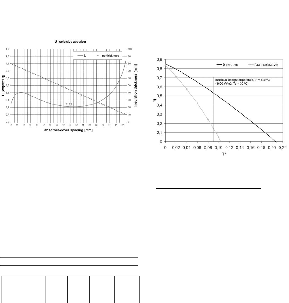
Fig.1 for the global heat loss coefficient variation
(considering fixed surface temperatures) with
absorber-cover spacing (and thus insulation thickness).
Fig. 1: Variation of global heat loss coefficient with
absorber-cover spacing.
4. PERFORMANCE ESTIMATE
Collector performance estimates were based on the thermal
model briefly described in 2 and on the design parameters
described in 3.
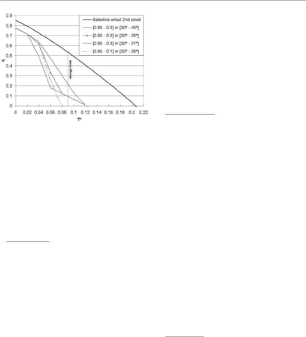
Considering the higher operating temperatures aimed for
the collector, second-order approximation efficiency
curve parameters were calculated for both absorber
possibilities.
TABLE 1: ESTIMATED EFFICIENCY CURVE
PARAMETERS AND STAGNATION TEMPERATURE (I
= 1000 W/m
2
; Ta = 30 ºC)
Absorber η0 a1 a2 Tf [ºC]
Selective 0.86 3.16 0.005 236.4
Non-selective 0.83 5.46 0.024 134.2
A benchmarking analysis revealed that while the adoption
of a non-selective absorber results in a rather modest
competitiveness (performance wise), especially in face of
selective or evacuated tube collectors, the adoption of a
selective absorber places the collector amongst the best
available products.
Yet, while non-selective absorber estimates point towards a
stagnation temperature close to the maximum temperature
design parameter, the use of a selective absorber in a
high-performance collector requires the adoption of
temperature control strategies, which may limit the
maximum temperature achieved.
Fig. 2: Estimated efficiency curves.
5. TEMPERATURE CONTROL STRATEGIES
In view of the parameters influencing the collector
performance, temperature control strategies might act upon:
the optical efficiency, after a temperature based change
of optical properties of glazing (transmissivity) and/or
absorber (absorptivity);
heat losses, after a temperature based change of
convection, radiation or conduction heat losses.
Considering the nature of the product under development,
namely the need for low maintenance requirements, the
strategies to be adopted should be temperature driven and
based in passive systems.
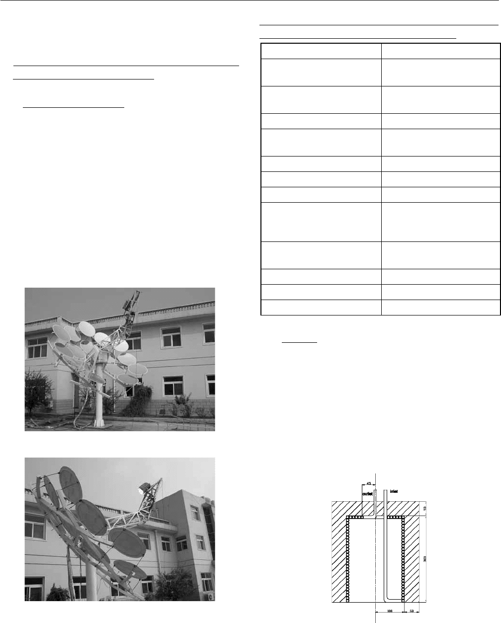
A first attempt of such a strategy aimed at the adoption of a
second polycarbonate glazing with variable transmissivity.
Different transmissivity limits and activation temperatures
were simulated, as illustrated in Fig. 3.
Simulation results revealed that such strategy presents two
main disadvantages:
an initial optical efficiency penalty affecting collector
performance at any temperature level;
3 SOLAR COLLECTOR TECHNOLOGIES AND SYSTEMS
643
Fig. 3: Estimated efficiency curves after adoption of second
glazing with variable transmissivity properties and
temperature activation limits.
attainment of a given stagnation temperature implies
activation at relatively low temperatures, which imposes
an additional penalty to collector performance in the
range of operating temperatures.
In consequence, different passive temperature driven strategies
aiming heat loss variations are under study, at present.
6. CONCLUSIONS
The use of polymeric materials in the manufacturing of
solar collectors acquires particular interest, opening a full
scope of opportunities for lower production costs, by means
of cheaper materials or simpler manufacturing operations.
The maximum temperature restrictions imposed by the use
of low cost polymers, has been a limiting factor for
polymeric solar collectors performances.
Higher performance, leading to higher stagnation
temperatures, require high temperature polymers, at a much
higher cost, or adoption of temperature control strategies.
The present paper addresses the manufacturing of a high
performance solar thermal collector based in polymeric
materials, after adoption of passive and temperature driven
temperature control strategies.
A first attempt of such a strategy aimed at the adoption of a
second polycarbonate glazing with variable transmissivity.
Simulation results revealed that such strategy encompasses
a strong penalty on collector performances.
At present, different passive temperature driven strategies
aiming heat loss variations are under study, aiming a final
product which gathers the advantages of lower construction
costs and high performance in hot water production
temperature ranges.
7. NOMENCLATURE
a
1
- global heat loss coefficient, [W/(m
2
ºC)]
a
2
- temperature dependent heat loss coefficient, [W/(m
2
ºC)]
G
col
- global irradiance incident on the aperture, [W/m
2
]
h
abs-cov,rad
- absorber-cover radiation heat loss coefficient,
[W/(m
2
ºC)]
h
abs-cov,conv
- absorber-cover convection heat loss coefficient,
[W/(m
2
ºC)]
h
cov.amb,rad
- cover-environment radiation heat loss
coefficient, [W/(m
2
ºC)]
h
cov-amb,conv
- cover-environment convection heat loss
coefficient, [W/(m
2
ºC)]
I - beam radiation, [W/m
2
]
T
a
- air temperature, [ºC]
T
f
- average heat transfer fluid temperature, [ºC]
U - global heat loss coefficient, [W/(m
2
ºC)]
U
front
- front side heat loss coefficient, [W/(m
2
ºC)]
U
back
- back side heat loss coefficient, [W/(m
2
ºC)]
α - absorptivity
ε - emissivity
η - collector efficiency
η
0
- collector optical efficiency
Κ(θ) - incidence angle modifier (IAM)
θ - incidence angle, [º]
8. REFERENCES
(1) Duffie, J.A., Beckman, W.A., “Flat-Plate Collector
Performance”. In: Duffie, J.A., Beckman, W.A., “Solar
Engineering of Thermal Processes”, John Wiley &
Sons Inc., New York, pp. 250-281, 1980.
(2) Rabl, A., “Active Solar Collectors and their
applications”, Oxford University Press, Oxford, 1985.

THE EXPERIMENTAL ANALYSIS ON THERMAL PERFORMANCE
OF A SOLAR DISH CONCENTRATOR
Xin Li
Institute of Electrical Engineering, CAS
P.O. Box 2703
Beijing 100080, China
drlixin@mail.iee.ac.cn
Zhifeng Wang
Institute of Electrical Engineering, CAS
P.O. Box 2703
Beijing 100080, China
zhifeng@vip.sina.com
Meimei Zhang
Institute of Electrical Engineering, CAS
P.O. Box 2703
Beijing 100080, China
happymm1124@sina.com
Chun Chang
Institute of Electrical Engineering, CAS
P.O. Box 2703
Beijing 100080, China
chang21st@mail.iee.ac.cn
ABSTRACT
Thermal performance tests were performed for a
multifaceted solar dish concentrator, using water as the
working fluid at 31ć, 45ć, 53ć and 71ć to define the
instantaneous efficency curve. The heat loss coefficient and
the influence of the water flow rate on the thermal
performance were also analysed.
1. INTRODUCTION
Solar energy utilization is of great interest to facilitate
building of all energy conserving economy in the face of
limited energy supplies in China. One promising type of
solar thermal power utilizes high density concentrated solar
energy to generate electricity through a clean, sustainable,
high efficient process. Dish concentrating solar thermal
power systems can be used not only in distributed power
supplies, but also in centralized power stations. The solar to
electrical conversion efficiency is reported to be up to
29.4%, the highest among all solar thermal power
generating systems[1].
The thermal performance of solar dish concentrators must
be carefully studied to optimize the system. The U.S.
national standard ASHRAE 93-1986[2] is mainly used to
determine the thermal performance of non-focusing
concentrators. In China, the Chinese national standard
GB/T4271-2000[3] (ie. Test Methods for the Performance
of Flat Plate Solar Collectors) was developed from the
ASHRAE standard. The main characteristic of these
standards is that steady or quasi steady state conditions are
used for tests to measure the instantaneous efficiency curve
to analyze the collector thermal performance. In the
ASHRAE standard, the differences between the
instantaneous efficiency functions for non-focusing and
focusing collectors are mainly in the intercepts and slopes
which reflect the differences of how the collector absorbs
energy and how it loses energy to the surroundings. A
detailed analysis of a solar dish concentrating collector
would require calculations of the heat transfer loss
coefficient and heat removal factor based on the optical and
geometric characteristics of specific collector. There is
currently no thermal performance test standard for
concentrating collectors in China. This paper presents tests
of the thermal performance of a multifaceted solar dish
concentrator made to analyze the thermal loses so as to
optimize the design. The results also provide a basis for
establishing a solar dish concentrator thermal performance
3 SOLAR COLLECTOR TECHNOLOGIES AND SYSTEMS
645
test standard.
2. SOLAR DISH CONCENTRATOR AND THERMAL
PERFORMANCE TEST SYSTEM
2.1 Solar Dish Concentrator
The multifaceted solar dish concentrating collector was
designed by the Institute of Electrical Engineering, Chinese
Academy of Sciences and the Himin Solar Energy Group
was the first solar dish concentrating collector in China.
The collector was installed in the solar energy high
temperature test base in Tongxian district, Beijing, China.
The system included a solar dish concentrator and a cavity
receiver. Fig. 1 shows the design with the main parameters
listed in Table. 1. The system used a closed loop
elevation-azimuth tracking control system with an optical
sensor which gave very high tracking accuracy.
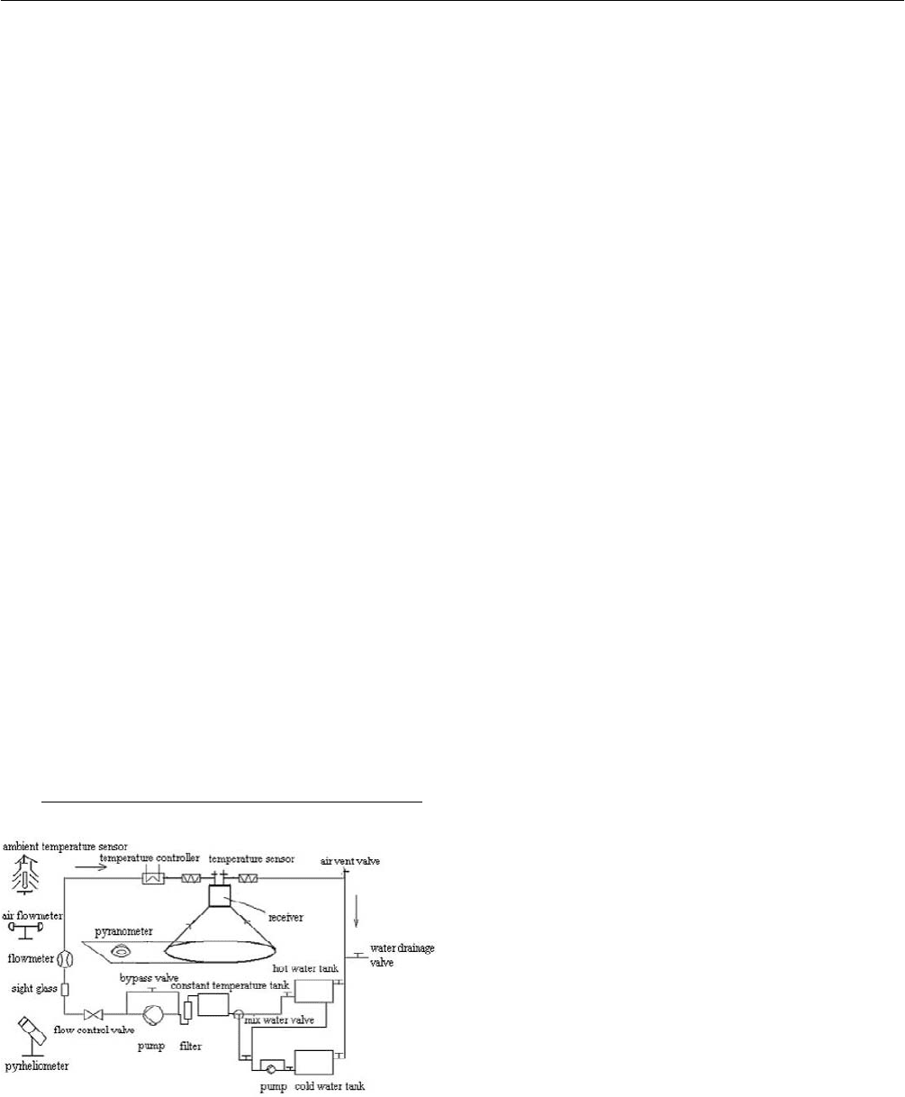
Fig. 1(a): Multifaceted solar dish concentrator.
Fig. 1(b): Multifaceted solar dish concentrator.
TABLE 1: MULTIFACETED SOLAR DISH CONCENT-
RATING COLLETOR DESIGN PARAMETERS
Concentrator
shape Approximate Paraboloid
2
4 3250xy=× ×
Aperture area per facet /
m
2
0.785
Number of facets 16
Equivalent solar dish
concentrator diameterˋm
5
Focal lengthˋm 3.25
Glass thickness / mm 1
Glass reflectance / % 90
Tracking control Closed loop
elevation-azimuth tracking
control
Geometric concentration
ratio
625
Receiver
type Cylindrical cavity receiver
Aperture diameter /m 0.2
2.2 Receiver
The receiver structure is shown in Fig. 2. The receiver
aperture was 200 mm indiameter with no glass cover. 10
mm outer diameter 1 mm thick copper tubing was coiled
along the inner and bottom surfaces to form the absorber.
The tubing was packed together with no spaces between the
coils to increase the surface area receiving the solar rays.
The inlet and outlet were run through the rear of the receiver.
Fig. 2: Receiver geometry.
Proceedings of ISES Solar World Congress 2007: Solar Energy and Human Settlement
646
The working fluid entering through the inlet then flowed to
the front part of the receiver and then around the receiver
cavity towards the outlet along the pipe. The flux density
was maximized on the aperture because it is also the focal
plane. Therefore, the flow direction from the front to the
back along the absorber surface improves the solar
absorption. The absorber was surrounded by firebricks as
the heat insulation material.
The receiver aperture did not have a glass cover which
would reduce the absorption and reflection by the glass, on
the other hand increase the reflection, convection and
radiation heat loss from the absorber. The net effect of a
glass cover on the receiver aperture would be to improve
the receiver thermal efficiency.
The receiver was meant to be a simple test bed with few
attempts made to enhance the absorption and reduce the
heat losses. The main objective was to demonstrate the
multifaceted solar dish concentrator and to make thermal
performance tests.
Therefore, the absorber surface was not coated with a
selective coating. So that the ratio of the absorption to the
emission is relatively small and reflection losses are large.
A selective coating would also enhance the receiver thermal
efficiency.
High temperature and high pressure metal hoses were used
for the inlet and outlet union pipe.
2.3 Experimental System for Thermal Performance Tests
Fig. 3: Solar dish concentrator thermal performance test
schematics.
The solar dish concentrator thermal performance test bed is
diagrammed in Fig. 3. Water from the cold water tank was
pumped to the gas combustion heater where it was heated
to a high temperature and stored in the hot water tank. Hot
water was mixed with cold water in the mixing valve to the
desired temperature and then stored in the constant
temperature storage tank until being pumped to the receiver.
Thermal insulation was wrapped around the pipeline to
prevent heat loss with the heat tapes wrapped around the
pipeline to prevent the heat loss. The constant temperature
tank not only mixed the hot and cold water to keep the
temperature uniform, but also buffered flow fluctuations.
The flow fluctuations were less than 0.9%, so the flow was
easily controlled to steady or quasi steady conditions.
Temperatures were measured by Pt100 resistance
thermometers on the cold tank, the hot tank, the constant
temperature tank and the receiver inlet and outlet. The
accuracy of the temperature measurements was within the
±0.1 K. The temperature sensors were installed within 200
mm of the receiver inlet and outlet with the pipeline in
front of and behind the sensor insulated by rock wool. The
Pt100 RTD which measured the ambient temperature was
placed in a well ventilated shelter less than 15 m from the
solar dish concentrator.
The flow rate was measured by an electromagnetic
flowmeter type DE43F produced by ABB corporation with
a measurement error less than ±0.5%.
The beam normal radiation was measured by a
pyrheliometer which tracked the sun. The pyrheliometer
was placed on the north of the solar dish concentrator
where no structures would affect the readings. The
pyranometer was mounted on the back of receiver so that it
tracked the sun with the moving solar dish concentrator to
measure the total solar radiation. The pyranometer was
mounted so that the solar dish concentrator structure did
not shade it.
The test data was acquired in a HP34970A data logger
every 10 seconds.
Water was used as the heat transfer fluid at inlet
temperatures of 31ć, 45ć, 53ć and 71ć with four
testing points per temperature.
3 SOLAR COLLECTOR TECHNOLOGIES AND SYSTEMS
647
3. DATA PROCESSING
As with nonconcentrating collectors, the solar dish
concentrating collectors thermal performance tests are
mainly controlled by the instantaneous efficiency curve, the
incidence angle modifier, which represents the effects of
the incidence angle and the time constant, which is a
measure of the system effective heat capacity.
3.1 Instantaneous Efficiency Equation
The useful energy delivered by the solar dish concentrating
collector is defined as a function of the water temperatures
entering and leaving the receiver and the mass flow rate:
()QCmTT=−
(1)
In the American standard ASHRAE93-1986, the
instantaneous efficiency for a concentrating collector is
given by:
()
()
A
CmT T
TT
A
FU
AAIAI
ηταργ
−
−
=−=
⋅
⎡⎤
⎢⎥
⎣⎦
(2)
Equation (2) is based on the gross area of the solar dish
concentrator,
g
A which is difficult to calculate for a
multifaceted solar dish concentrator. Since the aperture area
of the solar dish concentrator,
a
A , is a more relevant
indicator of the concentrated sun rays, an instantaneous
efficiency equation based on
a
A was used in this
paper[4]:
()
()
QCmTT
FU T T
F
IA IA CRI
ηταργ
−
−
== = −
⋅⋅
(3)
where
F : heat removal factor,
actual useful energy gain of a collector
useful energy gain if the whole receiver surface were at the fluid inlet temperature
F =
()τα : effective transmittance-absorptance product
U : receiver heat transfer loss coefficient which includes
conduction heat losses through the insulating materials,
convection heat losses through the receiver aperture,
radiation heat losses due to surface emissions from the
inner surface of the receiver and reflection heat losses
through the receiver[5],
CR : geometric concentration ratio of the solar dish
concentrating collectorˈ
A
CR
A
=
(4)
γ : intercept factor defined as the fraction of the reflected
radiation that is incident on the absorbing surface of the
receiver where
()
()
I
ydy
I
ydy
γ
=
∫
∫
as shown in Fig. 4 based
on the flux distribution in the f focal plane with the receiver
aperture extending from A to B, Kalogirou[6] defined the solar
)( yI
y
A
B
Fig. 4: The sketch map of optic capture ratio.
dish concentrating collector optical efficiency as the ratio
of the energy absorbed by the receiver to the energy
incident on the concentrator aperture:
()ηταργ= (5)
Therefore, the collector instantaneous efficiency can be
described by [4ˈ6],
Proceedings of ISES Solar World Congress 2007: Solar Energy and Human Settlement
648
FU T T
F
CR I
ηη
−
=−
(6)
4. THERMAL PERFORMANCE TESTS
The instantaneous efficiency curve based on the solar dish
concentrator aperture area is shown in Fig. 5.
0.00 0.02 0.04 0.06 0.08
0.57
0.58
0.59
0.60
0.61
0.62
0.63
0.64
experimental data
linar fit
instantaneous efficiency
(t -t )/I / (m .K)/W
Fig. 5: Transient efficiency for multifaceted solar dish
concentrator.
0.6154 0.4656
FU T T
F
CRI
ηη
−
=− = −
TT
I
−
The intercept for the curve given by Eq.(6)
is
0.6154F η = where the slope is 0.4656
FU
CR
=
.
Many flat plate solar collectors have been certificated by
the American Solar Rating and Certification Corporation[7].
The intercepts are about 0.8, the slopes are about
20W/m
2
gK for unglazed flat plate solar collectors. The
intercepts are about 0.6, the slopes are about 6W/m
2
gK for
glazed flat plate solar collector. The slope of the solar
dish concentrator instantaneous efficiency curve,
0.4656
FU
CR
=
, gives the gross heat loss coefficient as
larger than 186.29W/m
2
gK. This number is far larger than
for a flat plate solar collector because the gross heat loss
coefficient for the solar dish concentrator is based on the
receiver aperture area, while the heat loss coefficient for a
flat plate solar collector is based on the collector area. The
useful energy function written as follows:
() ( )QFAI FUATTτα=−− (7)
() ( )QFAI FUATTργ τα=−− (8)
The heat loss term shows that although the gross heat loss
coefficient for a solar dish concentrator is larger, the
product of the gross heat loss coefficient and the area is not
always larger. The receiver aperture area for these tests was
0.0314
m , while the equivalent flat plate solar collector
area would be about 2
m , thus the product of the gross
heat loss coefficient and the area for the flat plate solar
collector would be 10̚40W/K while that for the solar dish
concentrator was 5.726W/K. Therefore, for a solar dish
concentrator and a flat plate solar collector with the same
collecting area, the thermal performance for the dish would
be better than for the flat plate. Ryu et al[5] numerical
analysis of the thermal performance of cylindric and
conical receivers in the solar dish collectors showed that the
gross heat loss is 603W at a working temperature of 100ć
for the cylindric receiver (aperture diameter of 360mm).
The gross heat loss coefficient would then be 74.05W/m
2
K
and the product of the gross heat loss coefficient and the
aperture area would be 7.54W/K which is very close to but
not as good as current design.
The current results can not be directly compared to the
standard since the flow rate used in the tests was not the
same as in the standard. Duffie and Beckman[4] described
the influence of flow rate on the
FU and ()F τα for a
flat plate collector. The same methodology can be used to
analysis the influence of the flow rate on
FU and
()F τα ργ for a solar dish collector. The heat removal
factor can be related to the efficiency factor by [4]:
'
1exp
rl
p
mC
F
FAUF
AU F
mC
•
=−
⎛⎞
⎡⎤
⎜⎟
⎢⎥
−
⎜⎟
⎢⎥
⎜⎟
⎣⎦
⎝⎠
(9)
3 SOLAR COLLECTOR TECHNOLOGIES AND SYSTEMS
649
then,
ln 1
mC
FU A
FU
A
mC
=− −
⎛⎞
⎜⎟
⎜⎟
⎝⎠
(10)
and
()
()
1exp
1exp
(11)
FU F
r
FU F
mC
AFU
mC
AFU
AFU
mC
AFU
mC
τα ργ
τα ργ
==
−
=
−
⎛⎞
⎡⎤
⎜⎟
⎢⎥
−
⎜⎟
⎢⎥
⎜⎟
⎣⎦
⎝⎠
⎛⎞
⎡⎤
⎜⎟
⎢⎥
−
⎜⎟
⎢⎥
⎜⎟
⎣⎦
⎝⎠
FU can be obtained directly from the instantaneous
efficiency function, so that the influence of flow rate on the
instantaneous efficiency can be deduced from equation (11).
For the water flow rate of 0.02
kg/m si 1.0115r = and
the instantaneous efficiency in equation (6) can be written
as the followings:
0.6225 0.4710
FU T T T T
F
CR I I
ηη
−−
=− = −
Therefore, an increasing flow rate will increase the
collector efficiency with a small increase the heat losses.
5. CONCLUSIONS
A multifaceted solar dish concentrator was built and tested
in the Institute of Electrical Engineering, Chinese Academy
of Sciences for four inlet temperatures from ambient
temperature to 71ć to measure the concentrating dish
collector thermal performance. .
The measured instantaneous efficiency curve for the
multifaceted solar dish concentrator was:
0.6154 0.4656
FU T T T T
FK
CI I
ηη
−−
=− =− ˗
The receiver heat transfer loss coefficient based on the
receiver aperture area was larger than 186.29 W/m
2
gK.
Flow rate increases increase the collector efficiency but
also slightly increase the heat losses.
An equation for the solar dish concentrating collector
heat loss coefficient was not developed since the heat
losses depend on the receiver structure. As the receiver
working temperature increases, the edge effects become
more significant and conduction heat transfer may be
quite high. The analysis is compounded by the
non-uniformity of the radiation flux on the receivers.
Therefore, no general method can be developed to
estimate the thermal losses, and ultimately each receiver
geometry must be analyzed as a special case.
6. NOMENCLATURE
A
Aperture area of the solar dish concentrator,
m
A
Receiver aperture area, m
A
Total solar dish concentrator area, m
C Specific heat at constant pressure, kJ/kgK
CR Geometric concentration ratio of the solar
dish concentrating collector
F Heat removal factor
'F Efficiency factor
m Working fluid mass flow rate, kg/s
I
Beam normal solar radiation, W/m
2
,TT Temperatures of fluid entering and leaving
the receiver, ć
T Ambient temperature, ć
Q Rate of useful energy delivered by solar dish
concentrating collector, kW
U Receiver heat transfer loss coefficient,
W/m
2
K
ρ Reflectance of solar dish concentrator, %
γ intercept factor, %
τ Transmittance between concentrator and
receiver, %
α Receiver effective absorptance , %

Proceedings of ISES Solar World Congress 2007: Solar Energy and Human Settlement
650
()τα Effective transmittance-absorptance product
σ Stefen-Boltzman constant
η Solar dish concentrator efficiency based on
the gross solar dish concentrator area
η Solar dish concentrator efficiency based on
the solar dish concentrator aperture area
η Solar dish concentrator optical efficiency
7.
ACKNOWLEDGMENTS
The author thank to Mr. Xiliang Zhang and Mr. Wenfeng
Liang for building the multifaceted solar dish concentrator
and it’s tracking control system.
8. REFERENCES
(1) T. Mancini, P. Heller, B. Butler, B. Osborn, W. Schiel,
V. Goldberg, Reiner Buck, R. Diver, C. Andraka,
J. Moreno, “Dish-Stirling Systems: An Overview of
Development and Status”, Journal of Solar Energy
Engineering. 2003, 125,135-151.
(2) “Methods of Testing to Determine the Thermal
Performance of Solar Collectors”, ANSI/ASHRAE
93-1986. An American National Standard.
(3) “Test Methods for the Thermal Performance of Flat
Plate Solar Collectors”, GB/T4271-2000
. An Chinese
National Standard.
(4) J. A. Duffie, W. A. Beckman, “Solar Engineering of
Thermal Processes”, John Wiley & Sons, Inc. 1991.
(5) S. Ryu, T. Seo and Y. H. Kang, “Thermal Performance
of Receivers for a Multifaceted Parabolic Dish Solar
Thermal Collector”, ISES 2001 Solar World Congress.
2001,785-794.
(6) S. A. Kalogirou, “Solar Thermal Collectors and
Applications”, Progress in Energy and Combustion
Science. 2004, 30,231-295.
(7) Directory of SRCC Certified Solar Collector Ratings.
Solar Rating and Certification Corporation. 2003,
January 8.

THERMAL LOSSES IN SEALED, GAS-FILLED FLAT PLATE SOLAR COLLECTORS
Johan Vestlund
Solar Energy Research Center, SERC
Högskolan Dalarna
781 88 Borlänge, Sweden
jve@du.se
Jan-Olof Dalenbäck
Chalmers University of Technology
Buidling Services Engineering
412 96 Göteborg, Sweden
Jan-Olof.Dalenback@chalmers.se
Mats Rönnelid
Solar Energy Research Center, SERC
Högskolan Dalarna
781 88 Borlänge, Sweden
mrd@du.se
ABSTRACT
A sealed space between absorber and cover glass makes it
possible reducing the influence of humidity condensate and
dust at the same time as the enclosed space can be filled
with a suitable gas for lowering the losses. This paper is
about the size of the losses in these collectors. A calculating
model of a gas-filled flat plate solar collector was built in
Matlab with standard heat transfer formulas. It showed that
the total loss can be reduced up to 20% when changing to
an inert gas. It is also possible using a much shorter
distance and still achieve low losses at the same time as the
mechanical stresses in the material is reduced.
1. INTRODUCTION
The main aim is to study the possible improvements
regarding thermal performance of flat plate collectors with
different gas fillings between absorber and cover glass
more in detail. Other gases than air requires a sealed
space that has the advantage of reducing the influence of
condensate and dust on the selective absorber surface and
lowering the heat losses. The disadvantage is however
that a more complicated design is required in order to
manage variations of the pressure in, or the volume of, the
gas filling. This work concentrates on the collector
performance when the gas pressure is 100 kPa, i.e. close to
the ambient air pressure..
2. BODY OF PAPER
2.1 Basic Theory
The top loss is a heat flow from absorber, via gas, glass,
upside convection layer and out to the ambient air. The heat
flow through the gas from absorber to glass is made of
conduction, convection and radiation. Equilibrium exists,
so the heat transfer from absorber to glass is the same as the
heat transfer from glass to the ambient air. Conduction and
convection is usually expressed in the same formula,
because they are dependant on each other. The total top loss
q
top
will be according to (1).
qqq qq=+=+ (1)
When calculating the backside losses the approach is the
same, except that it is possible just calculating a pure
conduction in the insulation between absorber and back side