U.S. Army Corps of Engineers. Engineering and Design Slope Stability
Подождите немного. Документ загружается.

EM 1110-2-1902
31 Oct 03
F-1
Appendix F
Example Problems and Calculations
F-1. General
This appendix presents a series of example problems and calculations. The examples illustrate the procedures
used in the Simplified Bishop and Modified Swedish methods of slope stability analysis and provide guidance
for checking and verifying the results of slope stability analyses. Examples for end-of-construction and
steady seepage conditions are presented in this appendix. Examples for rapid drawdown are presented in
Appendix G.
a. Manual and spreadsheet calculations of the type described here are performed to check the results of
computer analyses of slope stability. These analyses are performed to check the factors of safety calculated
for the critical slip surface, and for other slip surfaces considered significant. The slip surfaces used for these
examples were selected to illustrate the computational procedures and are not the most critical slip surfaces
for the slopes.
b. As discussed elsewhere in this manual, the soil mass above the slip surface is subdivided into vertical
slices. Computer programs use more slices than are needed for hand calculations. Six to twelve slices are
sufficient for hand calculations. Fewer than 6 slices do not provide sufficient accuracy, and more than
12 slices makes the computations unwieldy, especially for computations using graphical methods.
c. In the following examples, computations are performed beginning with the uppermost slice near the
top of the slope and proceeding to the toe area, regardless of the direction that the slope faces. Thus, in some
cases the computations are performed for slices from left-to-right and in other cases for slices from right-to-
left, depending on the direction that the slope faces.
d. All of the computations for the procedures of slices were initially performed using a computer
spreadsheet program and then summarized in tabular form. The spreadsheet calculations were performed
with the number of significant figures used by the spreadsheet program, with no arithmetic rounding. Values
were rounded as appropriate for the tables presented in this appendix. Accordingly, some of the values may
differ slightly from what might be calculated by hand. For example the value shown for the term
Wsinα
may not be exactly equal to the values that would be computed using the values of the slice weight (W) and
the slope of the base of the slice (α
) shown in the tables. Any such discrepancies caused by rounding off are
insignificant.
F-2. Simplified Bishop Method
The Simplified Bishop Method is only applicable to analyses with circular slip surfaces. The computations
shown here have been performed using computer spreadsheet software. Detailed steps are presented below
for a total stress analysis of a slope with no water and for an effective stress analysis of a slope with water,
internal seepage, and external water loads.
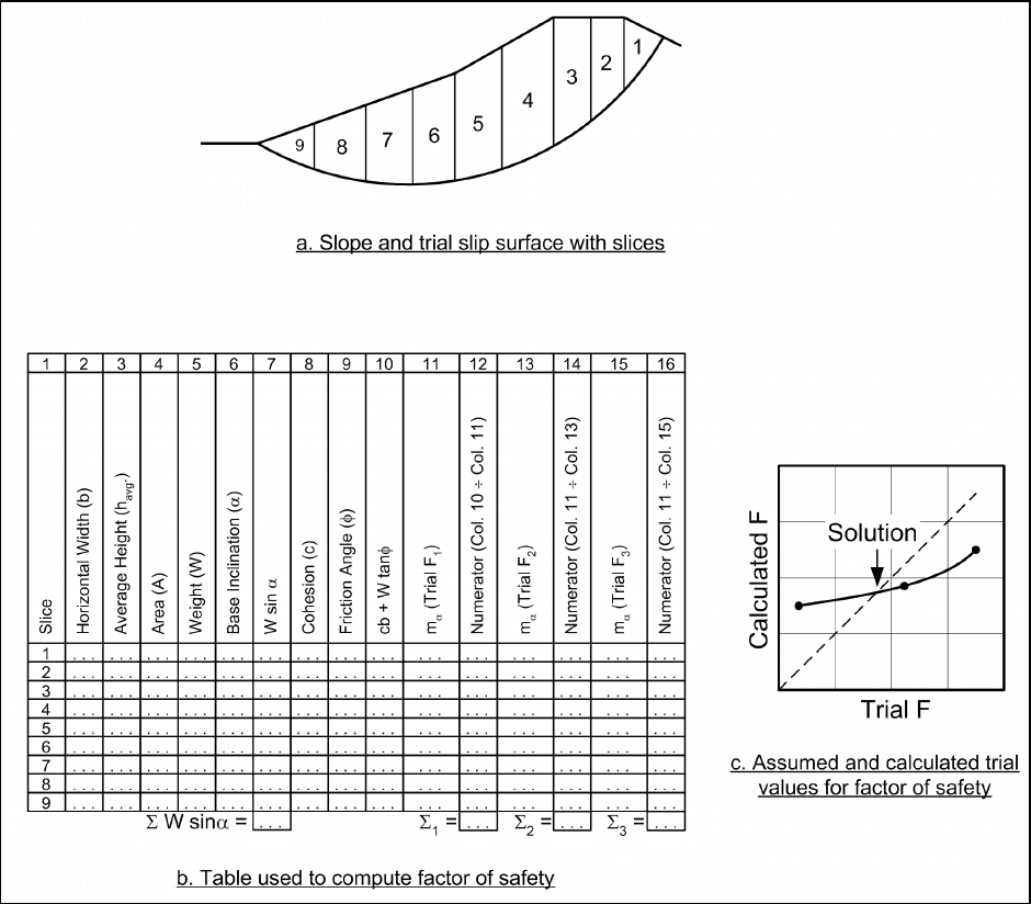
a. Slope without seepage or external water loads – total stress analyses. Computations for the
Simplified Bishop Method for slopes, where the shear strength is expressed in terms of total stresses and
where there are no external water loads, are illustrated in Figure F-1. As for all of the examples presented,
slices are numbered beginning with the uppermost slice and proceeding toward the toe of the slope. Once a
trial slip surface has been selected, and the soil mass is subdivided into slices, the following steps are used to
compute a factor of safety:
EM 1110-2-1902
31 Oct 03
F-2
Figure F-1. Simplified Bishop Method with no water - total stress analyses
(1) The width, b, average height, h
avg
, and inclination, α, of the bottom of each slice are determined
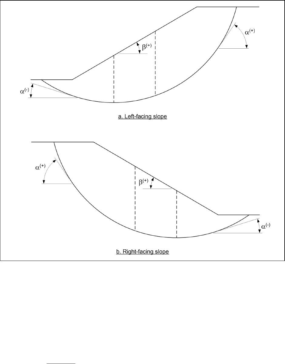
(Columns 2, 3, and 6 in Figure F-1b). The sign convention used throughout this appendix for the inclination,
α, is illustrated in Figure F-2. The inclination is positive when the base of the slice is inclined in the same
direction as the slope.
(2) The area, A, of each slice is calculated by multiplying the width of the slice by the average height,
i.e., A = b h
avg
(Column 4 in Figure F-1b).
(3) The weight of each slice is calculated by multiplying the total unit weight of soil by the area of the
slice, i.e., W =
γA. If the slice crosses zones having different unit weights, the slice is subdivided vertically
into subareas, and the weights of the subareas are summed to compute the total slice weight (Column 5 in
Figure F-1b).
(4) The quantity,
Wsinα , is computed for each slice, and these values are summed to obtain the term in
the denominator of the equation for the factor of safety (Column 7 in Figure F-1b).
EM 1110-2-1902
31 Oct 03
F-3
Figure F-2. Sign convention used for angles α and β
(5) The cohesion, c, and friction angle, φ, for each slice are entered in Columns 8 and 9 in Figure F-1b.
The shear strength parameters are those for the soil at the bottom of the slice; they do not depend on the soils
in the upper portions of the slice.
(6) The quantity c b W tan( )⋅+
φ
is computed for each slice (Column 10 in Figure F-1b).
(7) A trial value is assumed for the factor of safety and the quantity, m
α
, is computed from the equation
shown below (Column 11 in Figure F-1b):
sin tan '
mcos
F
α
α
φ
=α+ (F-1)
(8) The numerator in the expression for the factor of safety is computed by dividing the term cb + W
tan(φ) by m
α
for each slice and then summing the values for all slices (Column 12 in Figure F-1b).

EM 1110-2-1902
31 Oct 03
F-4
(9) A new factor of safety is computed from the equation:
cb Wtan
m
F
Wsin
α
⎡⎤
⋅+ ⋅
φ
⎢⎥
⎣⎦
=
α
∑
∑
(F-2)
This corresponds to dividing the summation of Column 12 by the summation of Column 7 in Figure F-1b.
(10) Additional trial values are assumed for the factor of safety and Steps 7 through 9 are repeated
(Columns 13 through 16 in Figure F-1b). For each trial value assumed for the factor of safety, the assumed
value and the value computed for the factor of safety using Equation F-2 are plotted as shown in Figure F-1c.
The chart in Figure F-1c serves as a guide for selecting additional trial values. Values are assumed and new
values are calculated until the assumed and calculated values for the factor of safety are essentially the same,
i.e., until the assumed and calculated values fall close to the broken 45-degree line shown in Figure F-1c.
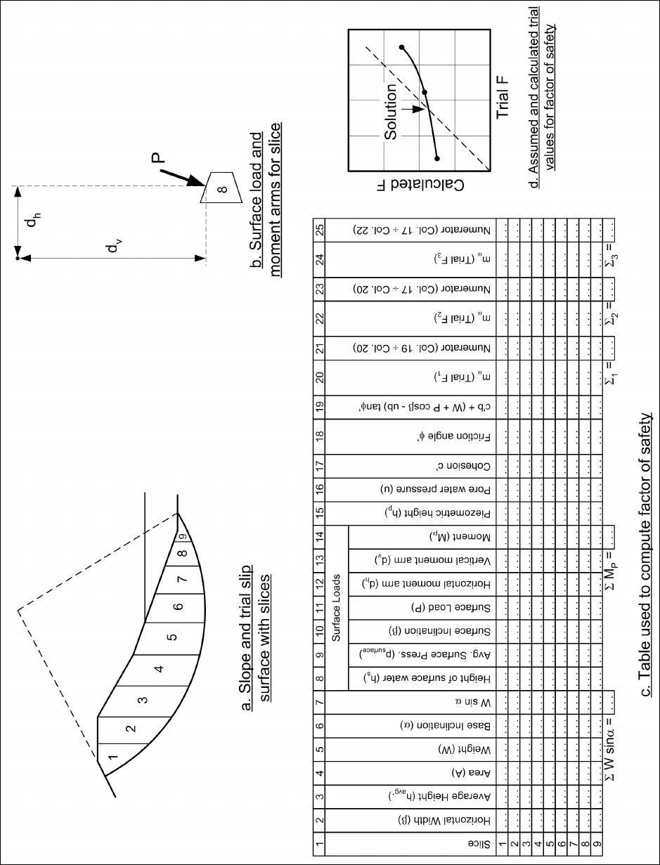
b. Slope with seepage or external water loads – effective stress analyses. Computations for slopes
where the shear strength is expressed in terms of effective stresses, and where there are pore water pressures
and external water loads, are illustrated in Figure F-3. In this case, the pore water pressures on the base of
each slice must be determined. Loads from external water are included in all analyses, whether they are
performed using total stress or effective stress. External water may be represented either as another soil, as
described in Appendix C, or as an external force. In the description which follows, water is represented as an
external load rather than as soil. Accordingly, a force on the top of the slice and the moment the force
produces about the center of the circle must be computed. For a given trial circle, the following steps are
required:
(1) For each slice the width, b, bottom inclination, α, and average height, h
avg.
, are determined
(Columns 2, 3, and 6 in Figure F-3c). The sign convention used for the angle, α, is illustrated in Figure F-2.
(2) The area of the slice, A, is computed by multiplying the width of the slice by the average height, h
avg.
(Column 4 in Figure F-3c).
(3) The weight, W, of the slice is computed by multiplying the area of the slice by the total unit weight of
soil: W = γA (Column 5 in Figure F-3c). If the slice crosses zones having different unit weights, the slice is
subdivided vertically into subareas, and the weights of the subareas are summed to compute the total slice
weight
(4) The term Wsin α is computed for each slice and then summed for all slices to compute
Wsinα
∑
(Column 7 in Figure F-3c).
(5) The height, h
s
, of water above the slice at the midpoint of the top of the slice is determined (Column 8
in Figure F-3c).
(6) The average water pressure on the top of the slice, p
surface.
, is calculated by multiplying the average
height of water, h
s
, by the unit weight of water (Column 9 in Figure F-3c).
(7) The inclination of the top of the slice, β, is determined (Column 10 in Figure F-3c). The sign
convention for this angle is shown in Figure F-2. β is positive, except when the inclination of the top of the
slice is opposite to the inclination of the slope. Negative values of β will exist when the inclination of the
slope is reversed over some distance, such as a “bench” that is inclined inward toward the slope.
EM 1110-2-1902
31 Oct 03
F-5
Figure F-3. Simplified Bishop Method with water - effective stress analyses

EM 1110-2-1902
31 Oct 03
F-6
(8) The length of the top of the slice is multiplied by the average surface pressure, p
surface
, to compute the
external water force, P, on the top of the slice (Column 11 in Figure F-3c). The force P is equal to
surface
pb/cos()⋅
β
.
(9) The horizontal and vertical distances, d
h
and d
v
, respectively, between the center of the circle and the
points on the top center of each slice are determined (Columns 12 and 13 in Figure F-3c). Positive values for
these distances are illustrated in Figure F-3b. Loads acting at points located upslope of the center of the circle
(to the left of the center in the case of the right-facing slope shown in Figure F-3) represent negative values
for the distance, d
h
.
(10) The moment, M
P
, the result of external water loads is computed from the following (Column 14 in
Figure F-3c):
Phv
MPcosdPsind=
β
+
β
(F-3)
The moment is considered positive when it acts opposite to the direction of the driving moment produced by
the weight of the slide mass, i.e., positive moments tend to make the slope more stable. Positive moments are
clockwise for a right-facing slope like the one shown in Figure F-3.
(11) The piezometric height, h
p
, at the center of the base of each slice is determined (Column 15 in
Figure F-3c). The piezometric height represents the pressure head for pore water pressures on the base of the
slice.
(12) The piezometric height is multiplied by the unit weight of water to compute the pore water pressure,
u (Column 16 in Figure F-3c). For complex seepage conditions, or where a seepage analysis has been
conducted using numerical methods, it may be more convenient to determine the pore water pressure directly,
rather than evaluating the piezometric head and converting to pore pressure. In such cases Step 11 is omitted,
and the pore water pressures are entered in Column 16.
(13) The cohesion, c', and friction angle, φ', for each slice are entered in Columns 17 and 18 in
Figure F-3c. The shear strength parameters are those for the soil at the bottom of the slice; they do not
depend on the soils in the upper portions of the slice.
(14) The following quantity is computed for each slice (Column 19 in Figure F-3c):
()
c'b W Pcos ub tan '++
β
−
φ
(F-4)
(15) A trial factor of safety, F
1
, is assumed and the quantity, m
α
, is computed from the equation shown
below (Column 20 in Figure F-3c):
1
tan 'sin
mcos
F
α
φ
α
=α+ (F-5)
(16) The numerator in the equation used to compute the factor of safety is calculated by dividing the term
()
c'b W Pcos ub tan '++
β
−
φ
by m
α
for each slice and then summing the values for all slices (Column 21 in
Figure F-3c).
(17) A new value is computed for the factor of safety using the following equation:

EM 1110-2-1902
31 Oct 03
F-7
()
P
c'b W Pcos ub tan '
m
F
1
Wsin M
R
α
⎡ ++
β
−
φ
⎤
⎢⎥
⎣⎦
=
α−
∑
∑∑
(F-6)
where R is the radius of the circle.
The summations computed in Columns 7, 14, and 21 of the table in Figure F-3c are used to compute the new
value for the factor of safety.
(18) Additional trial values are assumed for the factor of safety and steps 14 through 16 are repeated
(Columns 22 through 25 in Figure F-3c). For each trial value assumed for the factor of safety, the assumed
and calculated values of the factor of safety are plotted as shown in Figure F-3d, to provide a guide for
selecting additional trial values. Values are assumed and new values are calculated until the assumed and
calculated values for the factor of safety are essentially equal, i.e., until the assumed and calculated values fall
close enough to the broken 45-degree line shown in Figure F-3d.
F-3. Modified Swedish Method – Numerical Solution
The factor of safety can be calculated by the Modified Swedish Method using either numerical or graphical
procedures. The numerical procedure is presented in this section and the graphical procedure is presented in
Section F-4. Detailed steps are presented below for a total stress analysis of a slope with no water outside the
slope and for an effective stress analysis of a slope with internal seepage and external water loads.
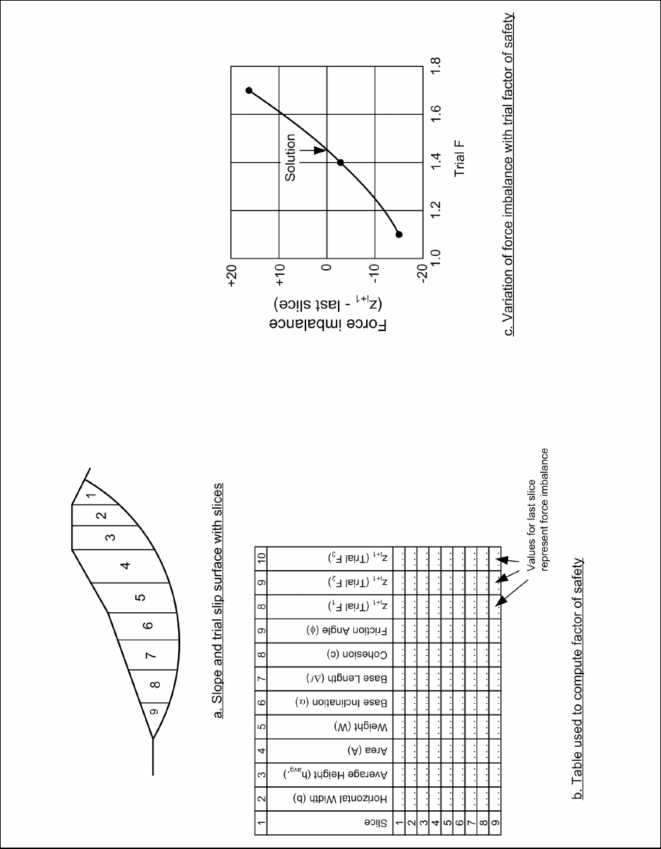
a. Slope without seepage or external water loads – total stress analyses. Computations for the
Modified Swedish Method with total stresses and no external water loads are illustrated in Figure F-4. The
Modified Swedish Method may be used with slip surfaces of any shape, and the procedure is the same
regardless of the shape of the slip surface. For simplicity, a circle has been used for the example illustrated in
Figure F-4. Once a trial slip surface has been selected and the soil mass has been subdivided into slices, the
steps listed below are used to compute a factor of safety. Slices are numbered beginning with the uppermost
slice and proceeding toward the toe of the slope.
(1) The width, b, average height, h
avg.
, and base inclination, α, are determined (Columns 2, 3 and 6 in
Figure F-4b).
(2) The area of the slice, A, is computed by multiplying the width, b, of the slice by the average height,
h
avg.
(Column 4 in Figure F-4b).
(3) The weight, W, of the slice is computed by multiplying the area of the slice by the total unit weight of
soil: W = γA (Column 5 in Figure F-4b). If the slice crosses zones having different unit weights, the slice is
subdivided vertically into subareas, and the weights of the subareas are summed to compute the total slice
weight.
(4) The length of the bottom of the slice, ∆
R, is determined; the length can be computed from the width, b,
and base inclination, α: ∆
R = b / cos α (Column 7 in Figure F-4b).
(5) The cohesion value, c, and friction angle, φ, are determined for the base of each slice (Columns 8 and
9 in Figure F-4b). The shear strength parameters are those for the soil at the bottom of the slice; they do not
depend on the soils in the upper portions of the slice.
EM 1110-2-1902
31 Oct 03
F-8
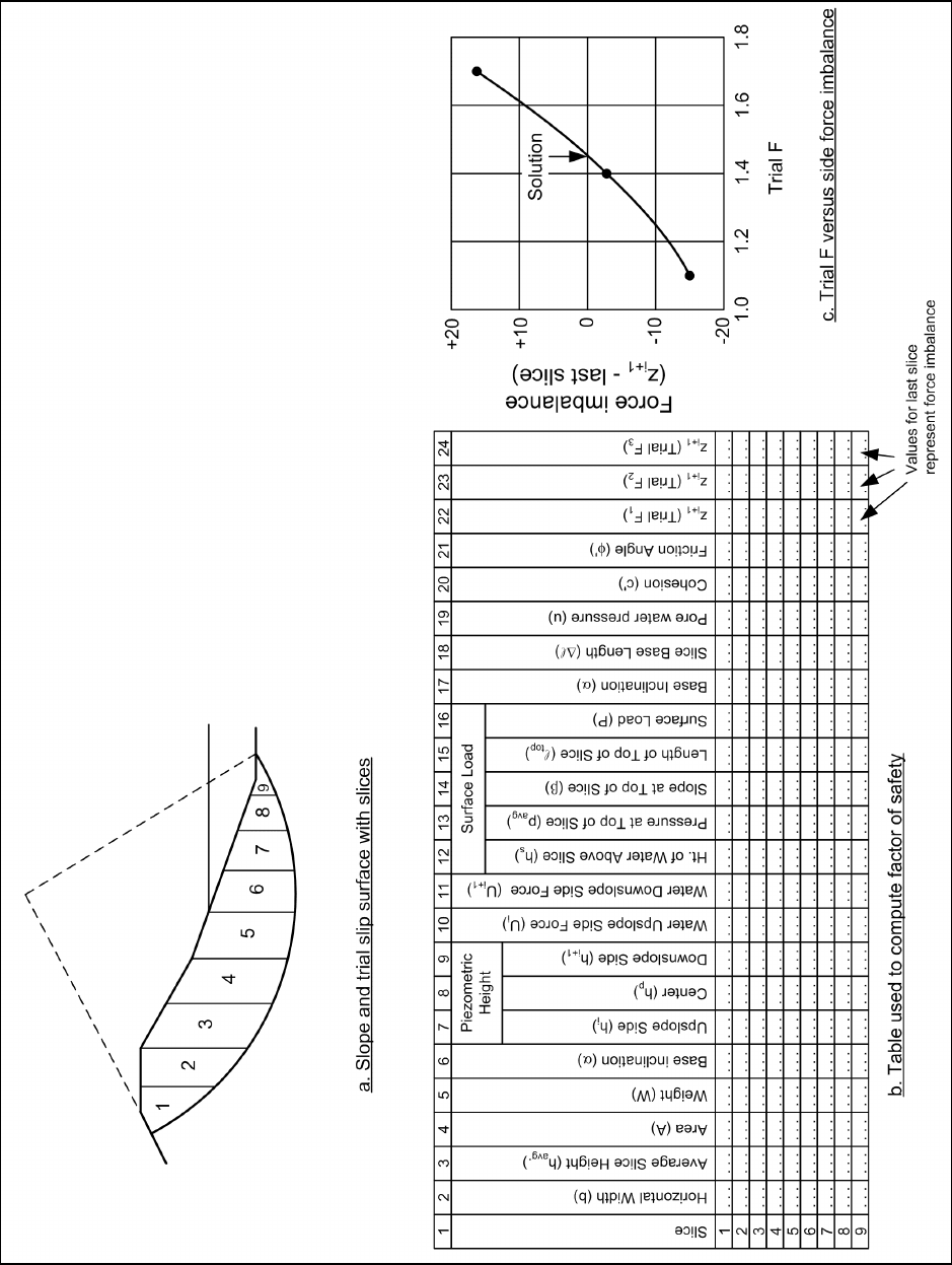
Figure F-4. Modified Swedish Method - numerical solution with no water - total stress analysis

EM 1110-2-1902
31 Oct 03
F-9
(6) The inclination, θ, of the interslice forces is determined. If the computations are being performed to
check an analysis performed using Spencer’s Method, the interslice force inclination determined from
Spencer’s Method should be used. Otherwise, the interslice force inclination should be assumed in
accordance with the guidelines and discussion presented in Appendix C.
(7) A trial factor of safety, F
1
, is assumed.
(8) Beginning with the first slice the side force, Z
i+1
, on the “downslope” side (left side for the slope
illustrated in Figure F-4) of each slice is computed from the equation:
()
()
i1 i
tan cos c
Wsin
FF
ZZ
tan sin
cos
F
+
φ
α⋅∆
⎡⎤
α− −
⎢⎥
⎣⎦
=+
φ
α−θ
α−θ +
A
(F-7)
(9) If the force computed for the last slice, Z
i+1
, is not sufficiently close to zero, a new trial value is
assumed for the factor of safety and the process is repeated. By plotting the force imbalance, Z
i+1
, for the last
slice versus the factor of safety, the value of the factor of safety that satisfies equilibrium can usually be found
to an acceptable degree of accuracy in about three trials (Figure F-4c).
b. Slope with seepage or external water loads – effective stress analyses. Computations for slopes
where the shear strength is expressed in terms of effective stresses and where there are pore water pressures
and external water loads are illustrated in Figure F-5. In addition to the quantities required when there is no
water, the pore water pressures on the base of each slice, along with the forces from water on the top of the
slice, must be determined. For a given trial slip surface, the following steps are required:
(1) For each slice, the width, b, average height, h
avg.
, and base inclination, α, are determined (Columns 2,
3, and 6 in Figure F-5b).
(2) The area of the slice, A, is computed by multiplying the width, b, of the slice by the average height,
h
avg.
(Column 4 in Figure F-5b).
(3) The weight, W, of the slice is computed by multiplying the area of the slice by the total unit weight of
soil: W = γA (Column 5 in Figure F-5b). If the slice crosses zones having different unit weights, the slice is
subdivided vertically into subareas, and the weights of the subareas are summed to compute the total slice
weight
(4) The piezometric height is determined at the upslope boundary, center and downslope boundary of
each slice (Columns 7, 8, and 9 in Figure F-5b). The piezometric height at the upslope and downslope
boundaries of the slice, h
i
and h
i+1
, respectively, are used to compute the forces from water pressures on the
sides of the slice. Here, a triangular hydrostatic distribution of pressures is assumed on the sides of the slice.
If the distribution of water pressures is more complex, it may be necessary to compute the water forces
differently from what is illustrated in Figure F-5. Assuming triangular distributions of water pressures
provides sufficient accuracy for most analyses. The piezometric height at the center of the slice, h
p
, represents
the pressure head for pore water pressures at the base of the slice (Column 8 in Figure F-5b).
(5) Hydrostatic forces from water pressures on the sides of the slice are computed from the equations
shown below (Columns 10 and 11 in Figure F-5b):
EM 1110-2-1902
31 Oct 03
F-10
Figure F-5. Modified Swedish Method - numerical solution with water - effective stress analysis