U.S. Army Corps of Engineers. Engineering and Design Slope Stability
Подождите немного. Документ загружается.

EM 1110-2-1902
31 Oct 03
F-31
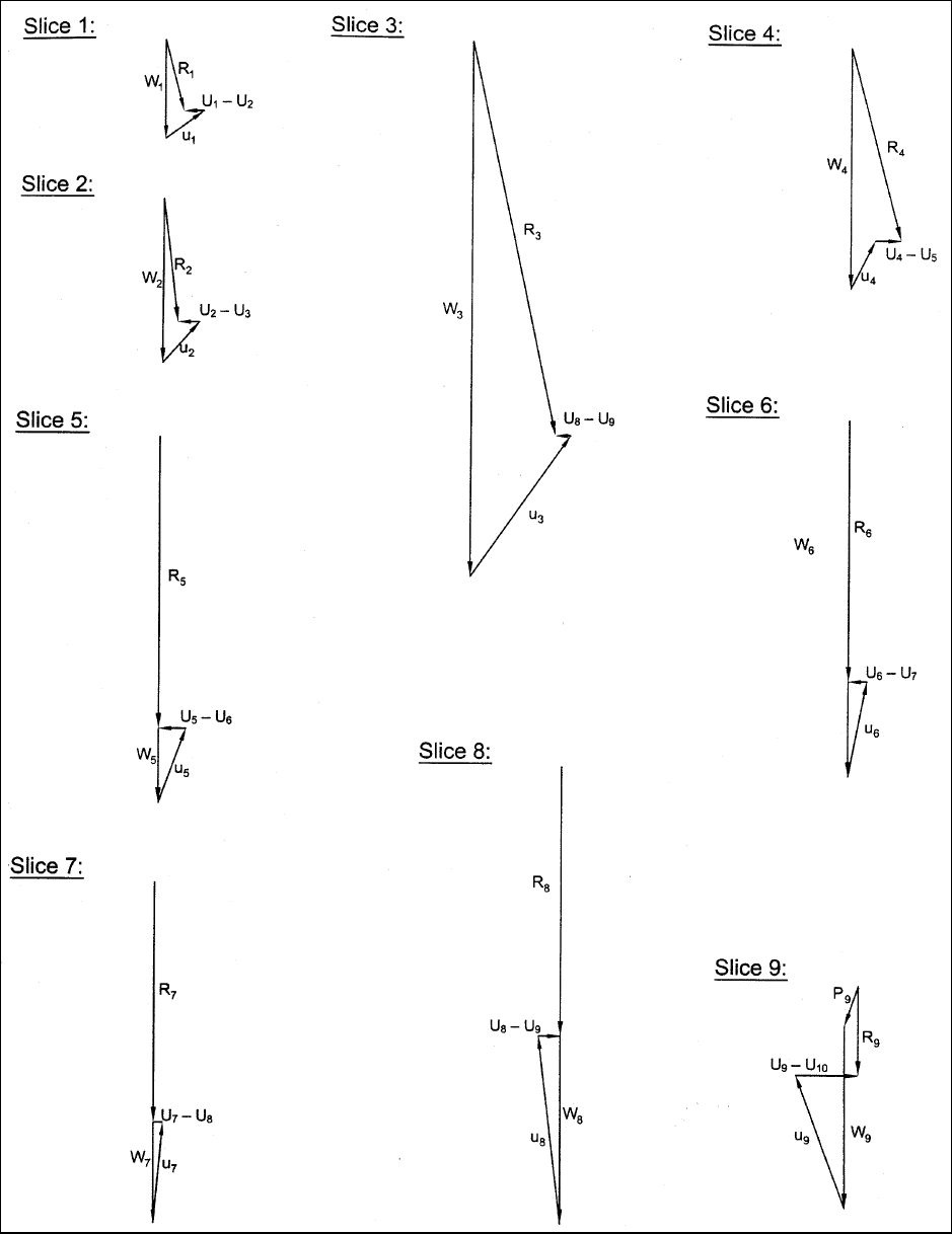
Figure F-20. Sample calculations for steady-state seepage – Modified Swedish Method – graphical solution –
resultant force (R) diagrams
EM 1110-2-1902
31 Oct 03
F-32
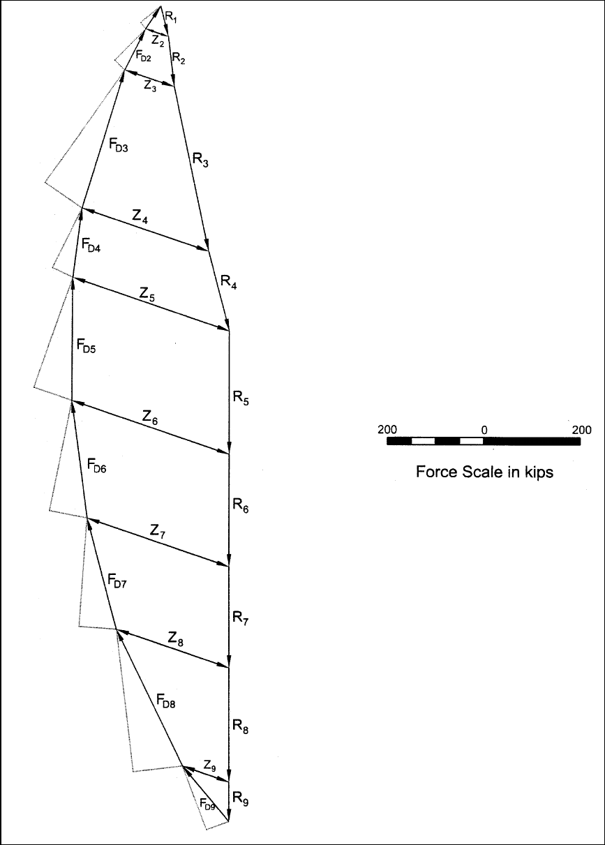
Figure F-21. Sample calculations for steady-state seepage – Modified Swedish Method – graphical
solution – force equilibrium polygons

EM 1110-2-1902
31 Oct 03
G-1
Appendix G
Procedures and Examples for Rapid Drawdown
G-1. General
Embankments may become saturated by seepage during a prolonged high reservoir stage. If subsequently the
reservoir pool is drawn down faster than the pore water can escape, excess pore water pressures and reduced
stability will result. For analysis purposes it is assumed that drawdown is very fast, and no drainage occurs in
materials with low permeability. Two separate procedures for computing slope stability for rapid drawdown
are presented in this appendix.
a. The first method is the one described in the 1970 version of this manual. It will be referred to here as
the “Corps of Engineers’ 1970 procedure.”
b. The second method is the one developed by Lowe and Karafiath (1960),
1
and modified by Wright and
Duncan (1987), and by Duncan, Wright, and Wong (1990). The objectives of the modifications were (1) to
simplify the method, and (2) to account more accurately for shear strength in zones where drained strength is
lower than undrained strength. The second method is more rational than the first, and is recommended. The
first method may be unrealistically conservative for soils that dilate during shear, and may lead to
uneconomical designs.
G-2. U.S. Army Corps of Engineers’ 1970 Procedure - Background
This method was presented in the previous (1970) version of this manual (USACE 1970). It involves two
complete sets of stability calculations for each trial shear surface. The first set of calculations is performed
for the conditions before drawdown, and is used to estimate the effective stresses to which the soil is
consolidated before drawdown. Although a factor of safety is computed in the first set of calculations, the
purpose of the first set of calculations is to compute the consolidation stresses. The effective stresses before
drawdown are used to estimate the undrained shear strengths that would exist during rapid drawdown. These
shear strengths are then used to perform a second set of stability calculations for conditions immediately after
drawdown. The factor of safety from the second set of calculations is the factor of safety for the rapid
drawdown condition.
a. First-stage computations. The first-stage computations are performed to calculate the effective
stresses to which the soil is consolidated prior to drawdown. The soil strengths and pore water pressures used
in the analysis are the same as those used for the long-term analysis of the steady seepage condition.
Effective stress shear strength parameters derived from Consolidated-Undrained (CU or R) tests with pore
water pressure measurements, or from Consolidated-Drained (CD or S) tests should be used. Pore water
pressures are computed from hydrostatic conditions or an appropriate seepage analysis. External water
pressures from the reservoir or other adjacent water are applied as loads to the face of the slope. The
objective of the computations is to evaluate the effective stresses on the base of each slice along the assumed
slip surface. The effective stresses are obtained by dividing the total normal force (N) on the base of each
slice by the length of the base, and subtracting the pore water pressure, i.e.,
c
N
'uσ= −
∆A
(G-1)
1
Reference information is presented in Appendix A.
EM 1110-2-1902
31 Oct 03
G-2
The stress σ'
c
is the effective normal stress, or consolidation stress, on the slip surface before drawdown.
b. Second-stage shear strengths. Once the effective consolidation stresses have been calculated from
the first-stage computations, shear strengths are estimated for the second stage. The shear strengths are
estimated from a “composite,” bilinear shear strength envelope. The envelope represents the lower bound of
the R and S strength envelopes.
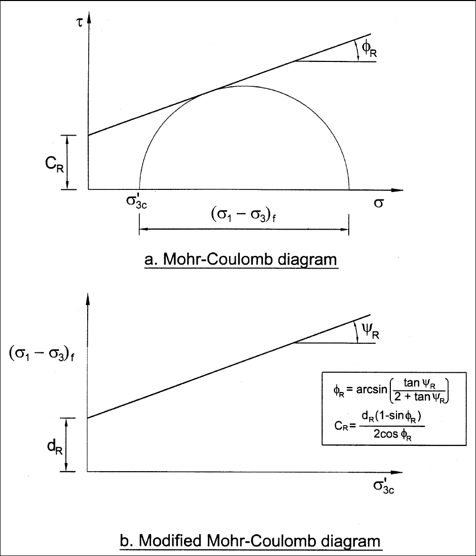
(1) The R envelope is determined by plotting a circle using the effective minor principal stress during
consolidation,
σ'
3c
, and the principal stress difference at failure, (σ
1
– σ
3
)
f
, as shown in Figure G-1, together
with the corresponding R envelope. Figure G-1a shows the envelope using conventional axes (
σ − τ); while
Figure G-1b shows the envelope on a modified diagram of (
σ
1
– σ
3
)
f
versus σ
3
. Neither envelope is a valid
Mohr-Coulomb envelope, because they are plotted using one stress that existed during consolidation,
σ'
3c
,
and another stress that existed at failure, (
σ
1
– σ
3
)
f
. Accordingly, this envelope is not consistent with the
fundamental principles of soil mechanics. It is empirical and should only be used in empirical procedures like
the 1970 procedure for rapid drawdown.
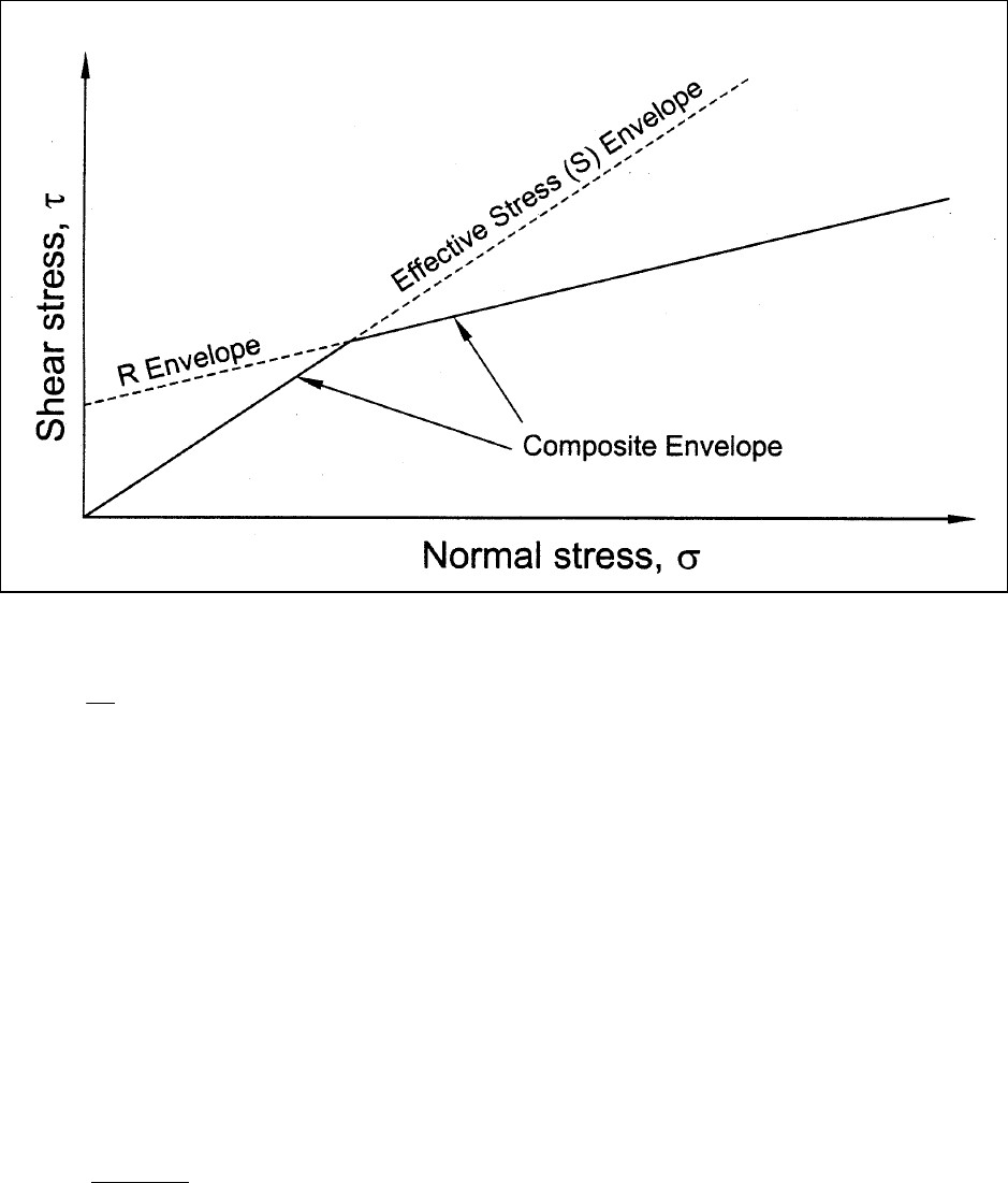
(2) The composite envelope used to determine the shear strengths for the second-stage computations is
shown in Figure G-2. The envelope represents the lower bound of the empirical R envelope described above,
and the effective stress S envelope. Shear strengths are determined for the second-stage computations using
the effective normal stress calculated for the first stage (from Equation G-1) and the composite envelope
shown in Figure G-2. Shear strengths are determined in this manner for each slice whose base lies in material
that does not drain freely.
c. Second-stage computations. The second-stage computations are performed to calculate the stability
immediately after drawdown. For materials that do not drain freely the shear strengths are determined in the
manner described in G-2b. These strengths are assigned as values of cohesion, c, with
φ equal to zero. For
materials that drain freely, effective stress shear strength parameters, c' and
φ', are used, and appropriate pore
water pressures are prescribed. The pore water pressures for free-draining materials should represent the
values after drawdown has occurred and steady-state seepage has been established at the new lower water
level. The pore water pressures for materials which do not drain freely are set equal to zero. If a portion of
the slope remains submerged after drawdown, the external water pressures acting on the submerged part of
the slope are calculated and applied as external loads to the surface of the slope.
G-3. Improved Method for Rapid Drawdown – Background
This method was developed by Lowe and Karafiath (1960), and modified by Wright and Duncan (1987) and
Duncan, Wright, and Wong (1990). The method involves either two or three separate slope stability
calculations for each trial slip surface. The first computation is the same as that for the Corps of Engineers’
1970 procedure and is used to calculate the effective stresses to which the soil is consolidated before
drawdown. The second set of computations is performed using undrained shear strengths corresponding to
the effective consolidation stresses calculated in the first stage. If the drained shear strength is less than the
undrained shear strength for any slices, a third set of calculations is performed, using drained shear strengths
for those slices. The factor of safety from the last stage (the second or third stage) is the factor of safety after
rapid drawdown.
a. First-stage computations. The first-stage computations are the same as those for the Corps of
Engineers’ 1970 method. However, in addition to computing the consolidation normal stress on the base of
each slice,
σ'
c
, the shear stress at consolidation, τ
c
, is also calculated for each slice. The shear stress at
consolidation is calculated by dividing the shear force (S) on the base of the slice by the length of the base,
i.e.,
EM 1110-2-1902
31 Oct 03
G-3
Figure G-1. R Shear strength envelope used in Corps of Engineers′ (1970) method for rapid drawdown
EM 1110-2-1902
31 Oct 03
G-4
Figure G-2. Composite shear strength envelope used in Corps of Engineers′ (1970) method for rapid drawdown
c
S
τ=
∆
A
(G-2)
b. Second-stage shear strengths
. Two shear strength relationships are used to evaluate shear strengths
for the second-stage computations.
(1) The first is the relationship between undrained shear strength (shear stress on the failure plane at
failure),
τ
ff
, and effective normal stress on the failure plane during consolidation, σ'
fc
. This relationship can be
determined directly from the results of isotropically consolidated-undrained (CU or R) tests, or it can be
calculated from the strength parameters, c
R
and φ
R
, that are determined from the R envelope shown in
Figure G-1.
(a) To determine the relationship between
τ
ff
and σ'
fc
directly from the results of isotropically
consolidated-undrained triaxial compression tests, the shear stress on the failure plane at failure,
τ
ff
, is plotted
versus the effective stress on the failure plane at consolidation,
σ'
fc
. The values of τ
ff
and σ'
fc
are calculated
using the following equations:
13f
ff
()
cos '
2
σ−σ
τ=
φ
(G-3)
and
fc 3c
''σ=σ (G-4)
EM 1110-2-1902
31 Oct 03
G-5
where
(σ
1
– σ
3
)
f
= principal stress difference at failure
φ' = effective stress angle of internal friction
σ'
3c
= CU test consolidation pressure
σ'
fc
is equal to σ'
3c
because the consolidation pressure is the same on all planes in an isotropic consolidated
undrained triaxial test.
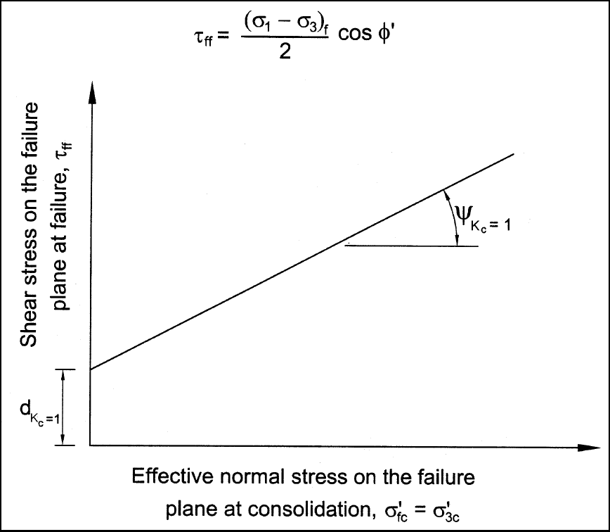
(b) An example relationship of τ
ff
vs. σ'
fc
is shown in Figure G-3. The intercept and slope of this
envelope are designated,
c
K=1
d
and
c
K=1
ψ
. If values of τ
ff
and σ'
fc
are determined directly from the CU test
results, the values of
c
K=1
d
and
c
K=1
ψ
are determined by drawing a line through the data and measuring the
intercept and the slope as indicated in Figure G-3.
Figure G-3. τ
ff
vs σ'
fc
Shear strength envelope from isotropically consolidated undrained (CU or R)
triaxial compression tests
EM 1110-2-1902
31 Oct 03
G-6
(c) The values of
c
K=1
d
and
c
K=1
ψ
are related to the intercept and slope (c
R
and N
R
) of the R-envelope
shown in Figure G-1 and can be computed if c
R
and φ
R
have been evaluated. The relationships between the
parameters
c
K=1
d
and
c
K=1
ψ
and the parameters c
R
and φ
R
are follows:
c
R
K1 R
R
cos cos '
dc
1sin
=
⎛⎞
φφ
=
⎜⎟
−φ
⎝⎠
(G-5)
c
1
R
K1
R
sin cos '
tan
1sin
−
=
⎛⎞
φφ
ψ=
⎜⎟
−φ
⎝⎠
(G-6)
(2) The other shear strength relationship needed for the second-stage computations is the effective stress
envelope. Although this envelope is for drained strengths, it may also be viewed as an envelope representing
the undrained shear strength of soil that is consolidated to stresses that bring the soil to failure before any
undrained loading is applied. In this case, no additional load can be applied in undrained shear before the soil
fails. In such a test, the stresses at failure are the same as those at consolidation.
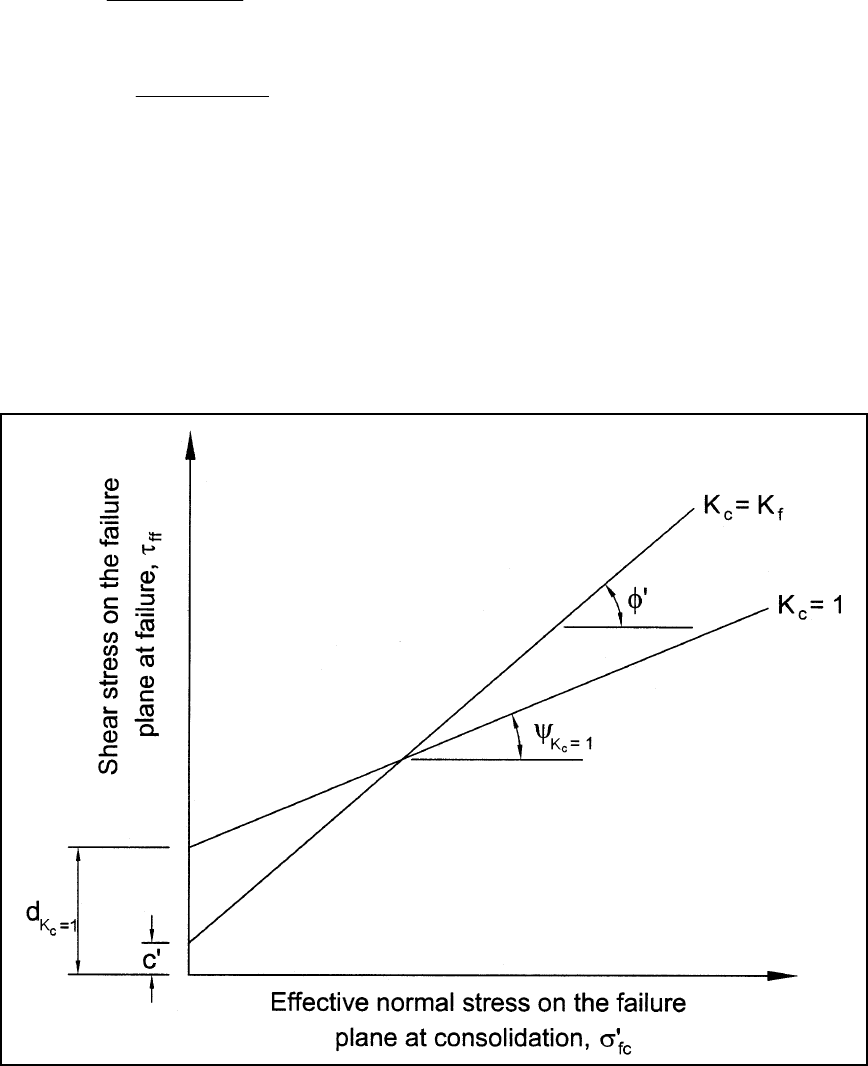
(a) The two shear strength envelopes that are used to determine undrained shear strengths for the second-
stage stability computations are shown in Figure G-4. Both envelopes represent relationships between
undrained shear strength, τ
ff
, and effective consolidation pressure on the failure plane, σ'
fc
.
Figure G-4. τ
ff
vs σ'
fc
Shear strength envelope used for improved procedure for rapid drawdown
analysis
EM 1110-2-1902
31 Oct 03
G-7
(b) The two envelopes shown in Figure G-4 correspond to the extreme possible values of the ratio of
σ'
1c
/σ'
3c
= K
c
. As discussed above, one of the envelopes corresponds to isotropic consolidation, or K
c
= 1, and
the other corresponds to the maximum possible ratio, or K
c
= σ'
1f
/σ'
3f
= K
f
. The undrained shear strengths
needed for the second-stage stability analyses are interpolated between these envelopes, using the value of K
c
for each slice determined from the first stage computations as the basis for interpolating between the
envelopes.
(c) As noted above, the values of K
c
ranges from 1.0 to K
f
. If c' = 0, the value of K
f
is given by the
following equation:
f
1sin '
K
1sin '
+
φ
=
−
φ
(G-7)
If c' is not equal to zero, the value of K
f
varies with the effective consolidation pressure σ'
fc
, as shown by the
following equation:
fc
f
fc
(' c'cos ')(1 sin ')
K
(' c'cos ')(1sin ')
σ+
φ
+
φ
=
σ−
φ
−
φ
(G-8)
(3) The following steps are used to compute undrained shear strength values for each slice using the
stresses σ'
c
and τ
c
from the first-stage computations:
(a) Compute undrained shear strengths from the two shear strength envelopes shown in Figure G-3. The
shear strengths are computed using the effective consolidation stress, σ'
c
, as follows:
cc c
(ff K 1) (K 1) c K 1
d'tan()
−= = =
τ=+σ
ψ
(G-9)
cf
(ff K K ) c
c' ' tan( )
−=
′
τ=+σ
φ
(G-10)
(b) Compute the effective principal consolidation stress ratio at failure, K
f
, from Equation G-7 or G-8.
(c) Calculate the principal stress ratio at consolidation, K
c
, for the stresses on the base of the slice,
cc
c
cc
sin ' 1
'
cos '
K
sin ' 1
'
cos '
φ
+
σ+τ
φ
=
φ
−
σ+τ
φ
(G-11)
where the stresses σ'
c
and τ
c
are those from the first-stage computations.
Equation G-11 is derived by assuming that the orientation of the principal stresses during consolidation is the
same as at failure, as suggested by Lowe and Karafiath (1960).
(d) Calculate, by linear interpolation between the two values of shear strength determined in Step a, the
undrained shear strength, τ
ff
, for the slice. The undrained shear strength is calculated using the following
equation:

EM 1110-2-1902
31 Oct 03
G-8
ccf
fcffK1 c ffKK
ff
f
(K K ) (K 1)
K1
−= −=
−τ + −τ
τ=
−
(G-12)
c. Second-stage computations
. The second-stage computations are performed to calculate stability
immediately after drawdown, assuming that all low-permeability materials are undrained. The low-
permeability materials are assigned undrained shear strength values calculated from Equation G-12, with φ set
equal to zero. Effective stress shear strength parameters are used for materials that drain freely, and
appropriate pore water pressures are prescribed. The pore water pressures for free-draining materials are
those after drawdown has occurred and steady-state seepage has been reestablished. The pore water pressures
in the low-permeability materials are set equal to zero. If a portion of the slope remains submerged after
drawdown, the external water pressures acting on the submerged part of the slope are calculated and applied
as external loads to the surface of the slope.
d. Strengths for third-stage computations.
Once the second-stage computations have been completed,
each slice is examined to determine if the drained strength would be less than the undrained strength
determined from Equation G-12. The drained shear strength is estimated as follows:
(1) The total normal stress on the base of each slice is calculated by dividing the normal force, N,
calculated in the second-stage computations by the length of the base, i.e.,
N
σ=
∆
A
(G-13)
(2) An approximate value of the drained effective stress, σ'
d
, after steady-state seepage is reestablished is
computed by subtracting the pore water pressure from the total stress, i.e.,
d
'uσ=σ− (G-14)
where σ is the total normal stress calculated in Equation G-13.
Because the total normal stress is based on the second-stage computations, it is not necessarily the same as the
total normal stress that would exist after drainage has occurred. However, it should not be much different,
and it is reasonable to assume that it is the same for the purpose of these analyses. The pore water pressure, u,
in Equation G-14 should be the pore water pressure after steady-state seepage is reestablished following
drawdown. The pore water pressure is not the same as the pore water pressure used in the first-stage
computations.
(3) The drained shear strength is estimated using the effective stress calculated in Equation G-14 and the
effective stress shear strength parameters, c' and φ', which are the same as those used in the first-stage
computations. The drained shear strength, s
d
, is calculated from:
dd
sc''tan(')=+σ
φ
(G-15)
(4) The drained shear strength calculated in Equation G-15 is compared to the value of undrained shear
strength for this slice that was used in the second-stage computations. If the drained shear strength is greater
than the undrained shear strength for all slices where the undrained shear strength was used previously, then
no further computations are required. In that case, the factor of safety after rapid drawdown is equal to the
factor of safety calculated for the second stage. If for any slice the drained shear strength is less than the
undrained shear strength used for the second-stage computations, a third-stage computation is performed. For