Wai-Fah Chen.The Civil Engineering Handbook
Подождите немного. Документ загружается.


In Situ Testing and Field Instrumentation 28-7
Field Vane Test
The FVT involves pushing a four-bladed vane having a height-to-diameter ratio of two into the soil and
then rotating the blade at a rate of 0.1 degrees/sec (ASTM 2573). This test provides a simple and
inexpensive means of estimating the undrained strength of cohesive soils, which is derived from the
maximum torque measured during rotation of the blade, assuming full and uniform mobilization of the
shear strength along the cylindrical surface created by the rotating vane. The use of this test is advocated
particularly in the case of relatively homogeneous clay deposits, in absence of shells, granular layers,
varves and fibers (Ladd, 1990). A correction (Bjerrum, 1972, 1973), based on the plasticity index of the
soil, is generally applied to the shear strength measured with the FVT, to obtain a “field” value of the
strength to be used in design. A correction for end effects that are associated with the mobilization of
shear strength on the top and bottom of the cylindrical volume of soil sheared by the vane is also necessary.
Despite the simplicity of the test, a number of procedural aspects (e.g., rate of rotation of the blade, delay
between vane insertion and testing); influence the test results (Ladd et al., 1977), and adherence to
standard practice and equipment is essential.
28.3 Instrumentation for Monitoring Performance
Planning of an Instrumentation Program
There are multiple reasons to use instrumentation. It may be that a project design has enough flexibility
to be changed if measurements made during early stages of construction indicate that changes are required
or could be beneficial. Alternatively, the facility under construction may be so important and its loss may
lead to so much damage or danger that instrumentation must be used to detect any deviations from the
assumed or predicted behavior of the facility, to allow timely implementation of previously planned
actions to either correct the deviation or minimize losses. In other cases, the construction procedure
(e.g., staged construction) may rely on indications of changes in the in situ conditions for proper execution
of the construction plan. Finally, when a new construction concept is used, instrumentation is sometimes
used to show or ascertain that the concept indeed works. Whatever the reason, detailed planning is
essential for a successful instrumentation project.
Design of the instrumentation program must rely on a clear definition of the geotechnical problem
that is being addressed and on the fundamental understanding of the mechanisms that control the
behavior. Once the objectives of the monitoring program are identified, its implementation requires
selection of the following: type and number of instruments to be used, specific locations where mea-
surements are to be made, installation procedures, and data acquisition system, methods for analyzing
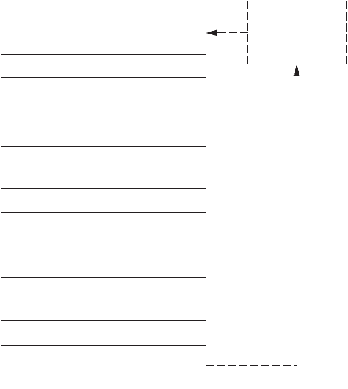
and interpreting the data. Figure 28.4 illustrates the main steps in the planning and implementation of
an instrumentation program.
Ultimate selection of the instruments depends on the quantities to be measured and estimates of the
magnitudes of changes in these quantities resulting from construction or operation of the facility. The
maximum expected change of the parameter to be measured will define the range for the instrument
selected to measure it. The minimum expected change defines the sensitivity or resolution of the instru-
ment. Such predictions are also required in defining criteria for remedial action, if the purpose of the
instrumentation is to ensure proper and safe operation of the facility.
When selecting instruments, several characteristics must be evaluated carefully:
1. Conformance: the instrument should conform to the surrounding soil or rock in such a way that
it does not alter the values of the properties it is intended to measure.
2. Accuracy: the measure should be as close as possible to the true value.
3. Repeatability: under identical conditions, an instrument must measure the same value for the
quantity it is intended to measure whenever a measurement is taken.
© 2003 by CRC Press LLC
28-8 The Civil Engineering Handbook, Second Edition
4. Resolution: the smallest division of the instrument read-out scale must be compatible with the
minimum expected change in the quantity being measured.
5. Sensitivity: the change in output per unit change in the input should be as large as possible to
optimize data acquisition and limit the effects of noise.
6. Linearity: the relationship between input and output should be as linear as possible for the range
in which the input is to be measured to facilitate data reduction.
7. Hysteresis: it is undesirable that a different value for the quantity of interest be measured depending
on whether the quantity is increasing or decreasing; this difference should be kept to a minimum,
particularly if cyclic measurements are needed.
8. Noise: random variations in the measurement should be limited.
9. Environmental compatibility: the instruments’ readings should not be affected by changes in
environmental conditions (e.g., temperature, relative humidity).
There are two approaches for selecting instrument location. Instruments can be installed in “trouble
spots,” such as points where it is expected there will be large stress concentrations or large pore pressure
increases, or where difficult soil conditions exist. Alternatively, they can be placed at a number of
representative points or zones. In either case, the designer should make every effort to ensure that the
instrument locations are consistent with the expected behavior of the facility and with the data required
for the analysis. It is also important that there is some redundancy in the instrumentation to filter
anomalies in measured quantities and ensure that the required information is obtained.
Testing and installation of the instrumentation is the next major step. All instruments should be
properly calibrated and tested before placement. Installation is one of the most critical steps in the entire
monitoring program because minor variations in the process can have significant effects on the performance
FIGURE 28.4 Planning of an instrumentation program. (From Ortigão, J.A.R. and Almeida, M.S.S. 1988. Stability
and deformation of embankments on soft clay, in Handbook of Civil Engineering Practice, P.N. Chereminisoff, N.P.
Chereminisoff and S.L. Cheng, eds., Technomic Publishing Co., New Jersey, vol. III, 267–336, With permission.)
Decide on the purpose of the
instrumentation
Process and analyze data
Select instruments and measurements
Plan instrument positions and
number of instrumented sections
Test and install instruments and
take initial readings
Obtain readings during and/or
after construction
Reassessment
Prediction of
system
behavior
© 2003 by CRC Press LLC
In Situ Testing and Field Instrumentation 28-9
of the devices and the reliability of the data. In many cases, hiring instrumentation specialists might be
justified.
During installation, steps should be taken to ensure the protection of the instrument (e.g., protection
from impact, water-tightness if required) and the instrument should be installed to minimize disturbance
of the medium under investigation.
Once installed, initial readings should be obtained and verified to ensure that changes from the time
of installation are represented accurately.
Data acquisition, processing, and analysis must be carried out in a systematic, organized way. Careful
recordkeeping is crucial and should include documentation of all construction activities and any signif-
icant events that may later be correlated with unanticipated or significant changes in the quantities
measured. Techniques and schedule for data acquisition depend on specific instruments and on the
requirements of the particular project. While many instruments still require on-site personnel, there is
increased availability of systems providing automated data acquisition and storage.
Instruments
In general, three primary quantities are measured in monitoring programs for traditional geotechnical
projects: loads and stresses, deformations, and pore pressures.
Instruments for Measurement of Loads and Stresses
In geotechnical engineering applications, load measurements are often required for load testing of deep
foundations, load testing and performance monitoring of tiebacks and rock bolts, and monitoring of
loads in strutting systems for deep excavations.
In most instances, such measurements are made with load cells. When accuracy is not a great concern,
a calibrated hydraulic jack can also be used. Based on the operating principle, there is a variety of different
types of load cells, including hydraulic, mechanical, electrical resistance, and vibrating wire cells.
Hydraulic cells consist of a chamber filled with fluid and connected to a pressure sensor. Load is applied
to a flat element that is in contact with the fluid and is free to move with respect to the rest of the cell.
The pressure generated in the fluid is measured by a pressure sensor, which can be a Bourdon gage, which
requires access to the cell for reading, or an electrical or pneumatic transducer for remote reading.
Mechanical and electrical resistance and vibrating wire cells function by measuring the deformation
of a load-bearing member and are based on the existence of a direct and unique relationship between
deformation and load.
In the case of a mechanical load cell, the deformation of either a torsion lever system or an elastic cup
spring is measured by dial gages. In electrical and vibrating wire load cells, the load-bearing member is
usually a steel or aluminum cylinder, the deformation of which is measured by electrical resistance strain
gages or vibrating wire transducers mounted at mid-height on its surface. Some of the gages (or trans-
ducers) are oriented for measuring axial strain, others for measuring tangential strains. The arrangement
and the connections are designed to minimize errors associated with load eccentricity.
Strain gages can be used effectively for measurement of loads or stresses in a structural member,
provided that the stress-strain relationship of the material on which they are mounted is known with
some accuracy. Their main advantages are that they can be placed almost anywhere in a structure, and
that, due to their limited cost, measurements can be performed at a number of different locations. A
distinction is generally made between surface-mounted strain gages, which are applied to an exposed
surface (for example, to the surface of a steel strut) and embedment strain gages, which are placed inside
a mass, for example, a concrete tunnel lining.
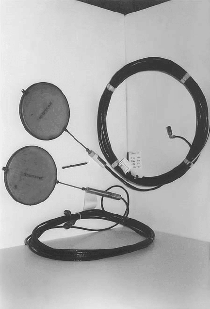
Pressure cells are used to measure total stresses behind retaining walls or underneath shallow foun-
dations, as well as within soil masses, such as fills. They are circular (Fig. 28.5) or rectangular pads with
metallic walls, and are of two types: hydraulic and diaphragm cells. In hydraulic cells, a fluid, such as
oil, is contained between the metallic walls. A pressure transducer positioned at the end of a rigid tube
connected to the inside of the cell measures the pressure in the fluid, which corresponds to the stress
© 2003 by CRC Press LLC
28-10 The Civil Engineering Handbook, Second Edition
acting on the face of the cell. In diaphragm cells, the pressure acting on the cell correlates with the
deflection of the face, which is measured through strain gages or vibrating wire transducers mounted on
the inside of the cell. Many factors, including characteristics of the cell, such as size, thickness, and
stiffness, affect the measurements performed. The accuracy with which total stresses are measured is
limited by conformance problems between the cell and soil arising from the difference in stiffness, the
effects of the installation procedures, and difficulties in calibrating the cell to represent field conditions
(Dunnicliff, 1988). When pressure cells are embedded for measurement of stresses inside a fill, arching
of stresses around the cell is often the source of considerable error in the measurements.
Instruments for Measurement of Deformations
A reliable way of measuring displacements of the ground surface or parts of structures that can be
observed above the ground surface is by surveying techniques.
The measurement of absolute motions requires that reference points be established. The reference for
the measurement of a vertical displacement is called a benchmark; for horizontal displacement mea-
surements, a reference monument is used. Reference stations should be motionless. If no permanent
structure, known to be stable and free of deformation, exists, a reference station (benchmark or monu-
ment) must be installed. A benchmark may consist of a rod or pipe extending all the way down to a
relatively incompressible layer, isolated from the surrounding soils to avoid deformation. This can be
accomplished by placing the rod inside a pipe without allowing any contact between the rod and the pipe.
FIGURE 28.5 Pressure cells for measurement of stresses in soil masses or contact stresses between soil masses and
concrete or steel surfaces. (Picture courtesy of A. Bernal and A. Karim, Bechtel Geotechnical Laboratory, Purdue
University.)
© 2003 by CRC Press LLC
In Situ Testing and Field Instrumentation 28-11
Points where deformations are to be determined are called measuring points and should satisfy three
requirements: first, that they are well marked so measurements are consistent; second, that they are placed
at the actual seat of movement; and third, that they last for the time during which measurements will
be needed. For measurements on structures, the first requirement can be satisfied by the use of bolts
embedded into wall surfaces. Sometimes a grid, scale, or bullseye may be used for improved readings.
If ground surface displacement measurements are desired and a pavement exists, particularly if it is a
structural pavement, it is important to place the measuring point below the pavement, in the ground,
to get an accurate measurement of the displacement. It is also important to go beyond the freeze-and-
thaw depth, and any layer of expansive or collapsible soil, unless it is desired to know the motions related
to these phenomena.
In addition to techniques that rely on direct visual observations, a number of other instruments are
used for measurement of deformations. The most common instruments include tiltmeters, inclinometers,
extensometers, settlement plates, and telltales.
Tiltmeters are instruments used for measuring the rotational component of motion of points on a
structure or in the ground, usually inside a borehole. They rely on a servo-accelerometer, an electrolytic
tilt sensor, or another gravity sensing device for the measurement. More common applications are for
measuring the rotation of retaining walls and concrete dams, and for monitoring landslides.
Inclinometers are devices used to measure the inclination with respect to the vertical. Their applica-
tions include monitoring of landslides, measurement of horizontal displacements of embankments on
soft ground and of motion of retaining structures, evaluation of deformations produced around a deep
excavation, and assessment of the location of a possible failure surface. In addition, inclinometers can
also be placed horizontally; for example, to determine the settlement or heave profile under an embank-
ment or a foundation.
An inclinometer system typically consists of a casing, a probe, and a readout unit. The casing, which
is generally formed by sections of grooved plastic pipe, may be installed in a borehole, embedded in a
fill or in concrete, or attached to a structure. Measurements are obtained by periodically lowering the
probe inside the casing all the way to a depth where no motion is expected. Grooves in the casing act as
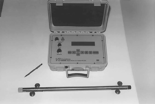
guides for the inclinometer probe, maintaining its orientation. The probe consists of a tube with two
sets of hinged wheels 0.50 m apart (Fig. 28.6), and typically contains two sensors: one aligned in the
FIGURE 28.6 Inclinometer and read-out unit. (Picture courtesy of A. Bernal and A. Karim, Bechtel Geotechnical
Laboratory, Purdue University.)
© 2003 by CRC Press LLC
28-12 The Civil Engineering Handbook, Second Edition
plane of the wheels and the other at 90 degrees. While various types of inclinometers are available, the
most common are based on servo-accelerometers, vibrating wire strain gauge transducers, and magneto-
restrictive sensors. Two sets of readings are typically obtained by rotating the probe 180 degrees to check
for errors in the data produced by faulty equipment or poor technique.
From the readings of the two sensors, which measure the angle of inclination to the vertical, the two
components of horizontal movement can be determined. Using as reference the initial profile of the
casing determined from the first set of measurements, the evolution of the entire borehole profile can
be assessed. Because errors in the use of inclinometers are often associated with spiraling of the casing,
particularly in the case of deep installations, a spiral sensor that allows correction of the inclinometer
data may be used.
In addition to the portable inclinometer probe, which is the most standard device used in practice,
in-place inclinometers may be used in critical applications requiring real time observations such as for
construction control and safety monitoring. These devices consist of a string of inclinometer sensors
connected in sequence through pivot points.
Extensometers are instruments for measuring the relative displacement between two points. Depend-
ing on how they are deployed in the field, these instruments can be classified as surface or borehole
extensometers. Surface extensometers include devices such as jointmeters and strainmeters used to
monitor cracks in structures, rock, or behind slopes, as well as gages used for monitoring convergence
within tunnels and braced excavations. All these devices function in a similar manner, by measuring the
relative movement of two pins or anchors fixed to the soil or rock with techniques as simple as a tape
measure or a dial gage or as sophisticated as vibrating wire transducers, LVDTs, and optical sensors.
Borehole extensometers are used to monitor the change in distance between two or more points along
the axis of a borehole, and are used for a variety of purposes including monitoring of settlement or heave
in excavations, foundations, dams and embankments, and monitoring of compression of piles.
Measurements are typically obtained by lowering a probe inside a casing and measuring the position
of reference points, typically rings or magnets, relative to a fixed point at the surface or at the bottom
of the borehole. Settlement and heave are determined comparing the initial and current values of these
measurements. Borehole extensometers are often used in conjunction with inclinometers and may share
the same casing.
In addition to the probe-based systems previously described, other devices permanently installed in
a borehole can be used to monitor changes in vertical position at one or more points. These instruments
typically consist of one or more anchors connected to rods, which extend to the surface. Movement at
depth is detected from the change in distance between the top end of each rod and a reference point.
Settlement plates carry out the same function for monitoring of deformations underneath embank-
ments constructed on soft clays. A 1- to 1.2-m square steel plate is embedded under the embankment
and connected to a 25- to 50-mm diameter coupled pipe, which extends all the way to the surface and
is isolated from the soil by a casing. The displacement of the plate is determined by measuring the
elevation of the top of the pipe.
The principle is also essentially the same for telltales, which are rods extending from a point inside a
structural element, such as a drilled shaft, and isolated from the surrounding concrete (or other material)
by means of a casing. Measurement of the displacement of the tip of the rod with respect to a reference
provides a measure of the displacement at the inaccessible point in the structure.
Instruments for Measurement of Pore Water Pressure
Piezometers are used to measure groundwater pressure. This is an essential parameter in all geotechnical
engineering projects, required for computation of effective stresses and earth pressures exerted on retain-
ing systems. Calculation of pore pressures may be straightforward if the depth to the groundwater table
is known and hydrostatic conditions are known to exist, but there are many situations where there is
enough uncertainty about pore pressure values to warrant the use of piezometers.
Piezometers are commonly used for monitoring groundwater draw-down around excavations; for
evaluating rates of consolidation during embankment construction on soft soils so that the fill may be
© 2003 by CRC Press LLC
In Situ Testing and Field Instrumentation 28-13
placed without risks of failure; for verification of pore pressure dissipation around a pile after driving to
determine the right time to start a static load test; and for monitoring of pore pressure build-ups produced
by ineffective drainage in earth dams.
Piezometers can be classified in five main groups: open standpipe, hydraulic, pneumatic, electrical,
and vibrating-wire.
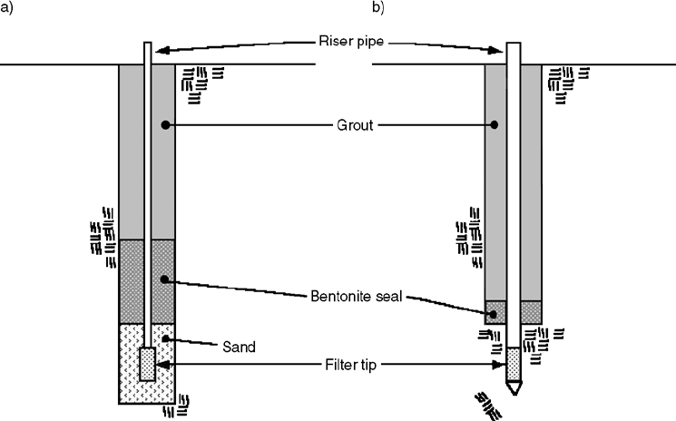
Open standpipe (or Casagrande) piezometers consist of a porous tip installed at the point where the
pore pressure readings are to be made. These piezometers are usually installed at the base of a borehole
with a diameter of 50 to 100 mm. They can be placed on the base of the borehole, which is then backfilled
with sand that will completely surround the porous tip, and sealed to prevent vertical migration of water
(Fig. 28.7(a)). Alternatively, they can be pushed into the base, so they are surrounded by natural material
(Fig. 28.7(b)). A single pipe (10–50 mm in diameter) is connected to the porous tip, which extends to
the ground surface and is generally open to the atmosphere. The level to which the water rises in the
tube is measured with a water level indicator and reflects the pore pressure at the porous tip.
In a hydraulic piezometer, twin tubing filled with de-aired water connects the porous tip to remote
pressure-reading devices, which may be mercury manometers, electrical pressure transducers, or Bour-
don gages. The double-tube system allows verification that there is no entrapped air, as well as flushing
of the system. The use of this type of device is advocated for long-term monitoring of pore water pressures
in embankment dams (Dunnicliff, 1988).
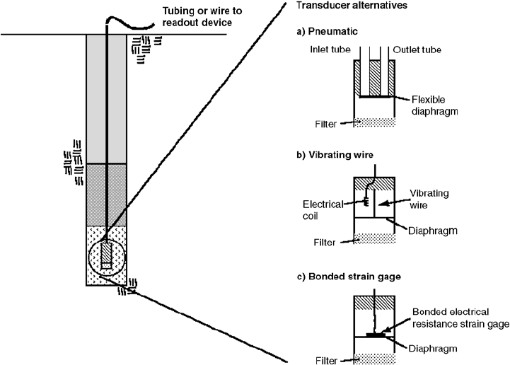
Pneumatic, electrical resistance and vibrating-wire piezometers, all contain a pressure diaphragm.
Water pressure acts on one side of this diaphragm, via a filter, and the difference between the piezometers
resides in the mechanism on the other side of the diaphragm used to measure the pressure.
In a pneumatic piezometer (Fig. 28.8(a)), a pneumatic indicator is connected to the diaphragm through
twin tubes. Measurement of the pressure at the diaphragm is performed by increasing the pressure of a
gas inside one of the tubes until it exceeds the water pressure, resulting in flow of the gas back up to the
indicator through the second tube.
In vibrating-wire piezometers (Fig. 28.8(b)) and electrical resistance (Fig. 28.8(c)), the diaphragm is
the sensing element of a pressure transducer contained in the same housing that holds the filter. The
transducers function by measuring the deflection of the pressure-sensitive diaphragm through a resistance
FIGURE 28.7 Schematic of standpipe piezometer (a) installed at bottom of a borehole and (b) pushed into base
of borehole.
© 2003 by CRC Press LLC
28-14 The Civil Engineering Handbook, Second Edition
strain gage bridge (two configurations are available: unbonded and bonded strain gages) mounted on
the diaphragm, or through measurement of the resonant frequency of a tensioned wire connected to the
diaphragm.
In addition to being installed in boreholes as shown in Fig. 28.8, pneumatic, electrical resistance, and
vibrating wire piezometers are all available also as push-in instruments. Dunnicliff (1988) points out that
while push-in piezometers are installed more easily and at less cost than in a borehole, problems arise due
to the potential for inadequate seal and for smearing and clogging. Selection of the appropriate piezometer
is a function of the purpose and the duration of the measurements, and is based on considerations of
accuracy, ease of installation, reliability, and durability of the instruments. In addition, an important
characteristic is the hydrodynamic lag time of the piezometer, which is the time required for equalization
of the pore pressure. Because it depends on the time necessary for water to flow in or out of the porous
tip, the lag time depends on the type of piezometer and on the permeability of the soil in which it is installed.
For example, Ortigão and Almeida (1988) show that in a soil with a hydraulic conductivity of 10
–10
m/sec,
the lag time corresponding to 95% pressure equalization can vary from approximately 1000 hours for a
typical Casagrande piezometer to approximately 10 seconds for a vibrating-wire piezometer.
For pore pressure measurements in unsaturated soils, any of the piezometers previously described can
be used depending on the specific application, provided that they are equipped with a fine, high bubble
pressure filter.
Table 28.2 summarizes some of the advantages and disadvantages of the described piezometers.
Examples of Applications of Field Instrumentation
Construction of Embankments on Soft Ground
Construction of embankments on soft soils presents risks associated with both short-term stability and
excessive long-term settlements arising from both primary and secondary consolidation. In these projects,
the use of the observational method is often valuable to ensure that construction proceeds safely and in
FIGURE 28.8 Schematic of (a) pneumatic, (b) vibrating wire piezometer, and (c) bonded strain gage electrical
resistance.
© 2003 by CRC Press LLC

In Situ Testing and Field Instrumentation 28-15
the most cost-effective manner; thus, monitoring of field performance plays an important role. This is
true particularly when more complex construction designs and procedures are used, as in the case of
staged construction, in which loading is applied in a controlled manner in different stages, relying on
the increase in shear strength due to consolidation for stability.
In the case of construction of embankments on soft soils, the goals of the field monitoring program,
which normally involves measurement of pore pressures as well as of vertical and horizontal deformations,
are generally the following:
1. Evaluate the progress of the consolidation process. Knowledge of the rate of consolidation is essential
so that construction schedules (e.g., placement of the pavement or structure, which would be damaged
by excessive settlements; timing of subsequent loading stages in the case of staged construction;
removal of surcharge in the case of preloading) can be safely and economically carried out. When
vertical drains are used, information might also be gathered on the effectiveness of the drains.
2. Assess at all times the stability of the embankment so that, in case of incipient failure, remedial
actions (such as the construction of a temporary berm, the reduction in the design fill elevation,
or the removal of part of the fill) may be implemented.
3. Obtain data that will allow improvement of the prediction of behavior during subsequent con-
struction phases, or even after construction. For example, if the project involves a preloading
phase, data gathered during construction may allow modification of the thickness of the surcharge
layer, based on revised estimates of soil compressibility.
TA B L E 28.2 Advantages and Disadvantages of Different Types of Piezometers
Piezometer Advantages Disadvantages
Open standpipe ∑ Highly reliable
∑ Low cost
∑ Simple to install
∑ Easy to read
∑ Can perform permeability tests
∑ Can obtain groundwater samples
∑ Long time lag especially in low
permeability soils
∑ Interference with construction when used
in embankments on soft soils
∑ Susceptible to damage by construction
equipment
Hydraulic twin
tubing
∑ Reliable for long term monitoring
∑ Flushing possible to remove air
∑ Can perform permeability tests
∑ Can measure negative pore pressure
∑ Complex installation
∑ Ve ry difficult and costly to implement
automated data acquisition
∑ Periodic flushing required
∑ Limitation on elevation above piezometric
head at which measurement is made
∑ Freezing problems
Pneumatic ∑ Short time lag (provided tubing not
excessively long)
∑ No freezing problems
∑ Can be used in corrosive environments
∑ Ve ry difficult and costly to implement
automated data acquisition
∑ Reading time increases with length of
tubing
Electrical
resistance
∑ Simple to install
∑ Short time lag
∑ Simple to read
∑ Easy to implement automated data acquisition
∑ Some types can be used for dynamic
measurements
∑ Can measure negative pore pressure
∑ No freezing problems
∑ Moderate to high cost
∑ Susceptible to damage by lightning
∑ Susceptible to damage by moisture
∑ Low electrical output
Vibrating wire ∑ Simple to install
∑ Short time lag
∑ Ve r y a ccurate
∑ Simple to read
∑ Easy to implement automated data acquisition
∑ Can measure negative pore pressure
∑ No freezing problems
∑ Moderate to high cost
∑ Susceptible to damage by lightning
© 2003 by CRC Press LLC
28-16 The Civil Engineering Handbook, Second Edition
As indicated by Ladd (1990) determination of the in situ rates of consolidation typically relies on
measurements of pore pressures and vertical settlements performed under the centerline of the embank-
ment with piezometers and extensometers, respectively. These data are also used to determine the in situ
compression curve. Measurement of the boundary pore pressures is also in general necessary.
Additional piezometers are typically installed under the slope and, when applicable, under the berm(s)
of the embankment. These instruments complement the data on rates of pore pressure dissipation,
allowing, in the case of staged construction, definition of the current effective stress profile from which
the updated undrained shear strength values to be used in the stability analysis can be estimated. In the
use of vertical drains, Ladd (1990) suggests that care should be placed in positioning the piezometers
near the midpoint of the drains and that part of the instrumentation be in place before the drains to
measure excess pore pressures generated by their installation.
In addition to the measurements performed under the centerline of the embankment, vertical defor-
mations of the soft soil layer may also be measured at other locations. This can be done, for example,
by using settlement platforms to define the embankment profile.
Pore pressure field data are also used to assess the conditions of stability of the embankment; however,
Ladd (1990) suggests that, as dramatic pore pressure increases often occur before or during actual failures,
pore pressures may not provide timely warning of impending failure. Field measurement of vertical and
especially horizontal displacements (which reflect deformations caused by undrained shear and are less
affected by consolidation) better serve this purpose. In this context, data obtained from inclinometers
installed at the toe of the embankment, which can be supplemented by monitoring of surface deforma-
tions with surveying techniques, provide the most unambiguous proof of foundation instability.
A thorough discussion on the use of field instrumentation in monitoring the performance of embank-
ments constructed on soft soils, with emphasis on the role of the stress-strain characteristics of the
foundation soil and on the interpretation of field data for stability analysis is provided by Ladd (1990).
An extensive list of case histories of instrumented embankments on soft ground is presented by Dunnicliff
(1988).
Static Load Tests on Deep Foundations
The main purpose of a standard static load test on a pile or drilled shaft is to obtain the relationship
between the load and the displacement at the head of the pile. Instrumented load tests aim to obtain the
load carried by the pile in each cross section, and, in particular, to separate the load carried by the pile
base from the load carried by the pile shaft. These data are used to verify that the pile or shaft can carry
the design load with an appropriate factor of safety, there are no major differences in behavior between
piles, and the piles have been appropriately installed or constructed. Load tests may be performed in the
design phase or during construction.
A typical arrangement for load-testing a pile is shown in Fig. 28.9 (ASTM D 1143). The figure refers
to the most common load test performed, which involves the application of an axial compressive load
using a hydraulic jack. (Testing under different loading conditions, such as tension or lateral loading, is
also possible.) Load is applied in increments that are generally a constant fraction of the maximum
applied load, which is either an estimate of the limit or plunging load or the design load multiplied by
an appropriate factor of safety. The maximum load is maintained for a long time, following which the
pile is completely unloaded in increments. Alternative loading protocols, in which loads are maintained
for shorter times, are also possible, but do not provide the best estimates of long-term pile capacity.
Reaction is usually provided by two piles, which are installed on each side of the test pile, at a sufficient
distance that they do not interfere (at least 5 to 8 pile diameters, according to Poulos and Davis [1990]).
Alternatively, a weighted platform can also be used for reaction. The hydraulic jack or a load cell is used
to measure the load applied at the pile head. A major concern is that the load is applied uniformly and
with no eccentricity. For these purposes, steel plates of appropriate thickness are positioned on the pile
cap and between the jack and the test beam and special care must be placed in centering the plates and
the jack. For the same reason, spherical bearings particularly when a load cell is used should be used.
© 2003 by CRC Press LLC