Wai-Fah Chen.The Civil Engineering Handbook
Подождите немного. Документ загружается.

Hydraulic Structures 37-17
discharge is then proportional to H
1/2
, where H is the difference between the reservoir elevation and the
elevation of the pipe outlet. Trash racks may be desirable to avoid clogging or damage by debris. In high
shaft spillways there is the possibility of cavitation in the bend between the vertical shaft and the conduit.
This situation must be avoided.
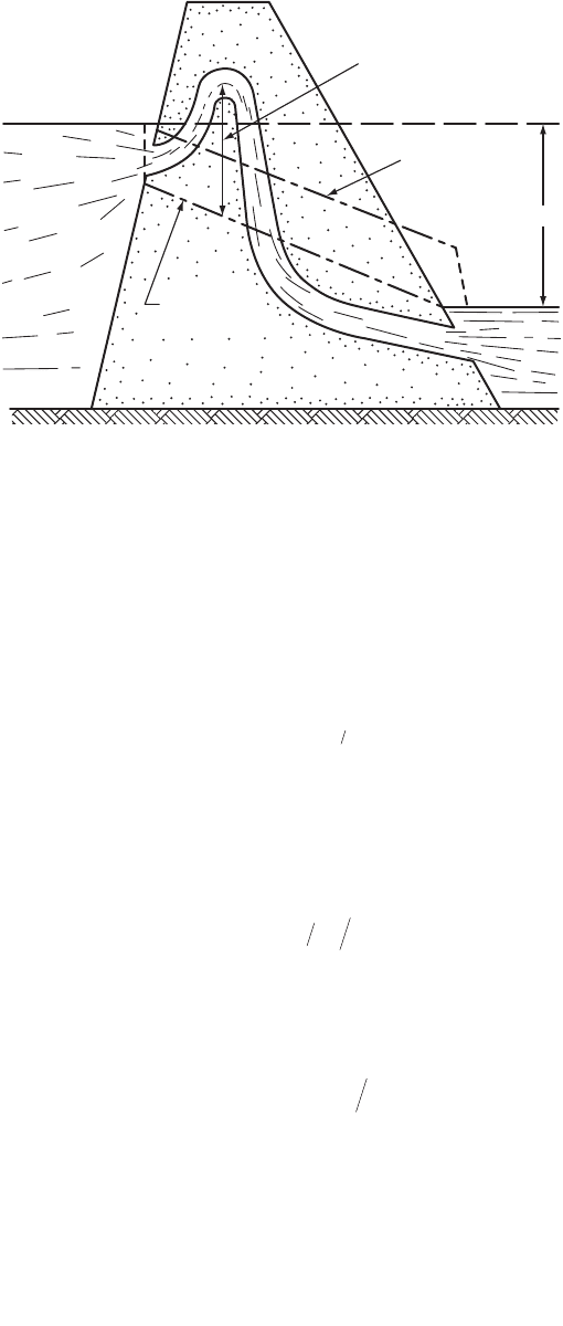
Siphon spillways can be used when large capacities are not required, space is limited and fluctuations
of reservoir level must be maintained within close limits. (Fig. 37.18). When the siphon flows full the
discharge is given by an orifice equation (see Chapter 29, Application 29.5).
(37.12)
where the coefficient of discharge C
d
is approximately 0.9, H is the difference in elevation between the
reservoir and the tailwater surface if the siphon outlet is submerged, or if it is free flowing H is the
difference in elevation between the reservoir and the siphon outlet.
In order to avoid cavitation the maximum velocity in the siphon must be limited to
(37.13)
in which V is the maximum velocity (in feet per sec), r
o
and r
i
are the outside and inside radii at the
crown of the siphon, assuming a free vortex at the crown (Morris and Wiggert, 1972).
Without contraction at the outlet, the maximum permissible head, H, associated with this velocity is
(37.14)
in which k
e
, k
f
, k
b
are the coefficients for entrance, friction and bend losses, respectively.
Labyrinth spillways are particularly advantageous when the available width is limited and large dis-
charges must be passed. They concentrate the discharge into a narrow chute. They are particularly well
suited for rehabilitation of spillways when the capacity has to be increased. They are more economical
than gated structures. The total length of the crest, L
T
, is
(37.15)
FIGURE 37.18 Siphon spillway. (Source: Morris, H.M. and Wiggert, J.M. Applied Hydraulics in Engineering, 1972,
Wiley, Fig. 6–20, p. 265.)
Hydraulic
grade line
Energy
grade line
Maximum negative
pressure head
H
QCAgH
d
=
[]
2
12
Vrrrrr
ioioi
=
()
[]
-
()
90 5. log
HkkkVg
efb
=++ +
()
()
12
2
LNLAD
T
=++
()
21
© 2003 by CRC Press LLC
37-18 The Civil Engineering Handbook, Second Edition
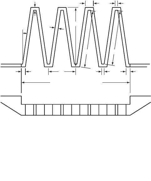
where L1 is the actual length of the side leg and A and D are shown in Fig. 37.19 and N is the number
of cycles (4 shown).
The effective length L of the crest in Eq. (37.10) is
(37.16)
where L2 is the effective length of the side.
Values of the discharge coefficient and details about the design of Labyrinth spillways can be found
in Tullis et al.(1995) and in Zerrouk and Marche (1995).
Stepped spillways and channels have been used since antiquity. The steps significantly increase the
energy dissipation over the spillway face thus reducing the size of the downstream stilling basin. Their
design has been reviewed by Chanson (1993).
Cavitation
High spillways can experience flow velocities of 10 to 15 m/s or more. When the high velocity flow
encounters a rapid convergence of the streamlines (perhaps caused by a surface irregularity or a bend),
then cavitation is likely to occur. Cavitation is the formation and subsequent collapse of vapor cavities
that occur when the fluid pressure gets below the vapor pressure. (Values of the vapor pressure head as
a function of temperature are given in Chapter 29, Fundamentals of Hydraulics, Tables 29.1 and 29.2).
On a spillway surface, when the streamlines of high velocity flow curve significantly at a surface irregu-
larity, then the pressure drops along the converging streamlines. Abrupt convergence of the streamlines
can produce pressure drops to the vapor pressure and vapor cavities begin to form. As the bubbles are
swept downstream in a region of higher pressure, they collapse near the concrete boundary. The implosion
of the bubbles creates a myriad of small high velocity jets that destroy the concrete surface. Measures to
control caviatation include close construction tolerance and aeration of the flow by means of aeration
devices. For further discussion of spillways considering cavitation and aeration see, for example, Wei
(1993). Cavitation in pipes is discussed in a subsequent section.
Spillway Crest Gates
Several types of gates can be installed on spillway crests in order to obtain additional storage. By opening
the gates, partial or full spillway discharge capacity can be obtained. The radial or Tainter gate has an
FIGURE 37.19 Labyrinth weir. (Source: Tul lis, J.P., Amanian, N. and Waldron, D. 1995. ASCE, Jour. of Hydraulic
Engineering, 121, 3, 247–255.)
α
t
DA
A
D/2D/2
W
W = Width of Labyrinth
PLAN VIEW
L1 L2
t
B
LNAL=+
()
22
© 2003 by CRC Press LLC
Hydraulic Structures 37-19
upstream surface which is a sector of a cylinder. Thus the hydrostatic force goes through the pivot or
trunnion located at the center of the circular arc. (see Chapter 29 on Fundamentals of Hydraulics,
Application 29.3). Other types of crest gates include vertical lift gates, flap gates, drum gates, roller gates
and inflatable gates. Design guidelines for spillway gates can be found in Sehgal (1996, 1993) and Sagar
(1995). Gates that overturn when the reservoir level exceeds a specified elevation are called fuse gates
(Falvey and Treille, 1995). Several gates are used and each gate is set to overturn with increasing reservoir
levels so that only the number of gates needed to pass the flow are overturned. The fuse plug performs
a similar function. It is an embankment that is designed to wash out in a predictable and controlled
manner when capacity is needed in excess of that of service spillway and outlet works (Pugh and Gray,
1984). In this case the entire fuse plug fails. Horizontal boards or stop logs laid between grooved piers
can be used in small installations. Flashboards or wooden panels held by vertical pins anchored on the
crest of the spillway are sometimes used in small installations to temporarily raise the water surface.
37.5 Outlet Works
Components and Layout
The purpose of the outlet works is to regulate the operational outflows from the reservoir. The intake
structure forms the entrance to the outlet works. It may also include trash racks, fish screens, and gates.
The conduit entrance may be vertical, inclined or horizontal. The conduit may be free flowing or under
pressure. For low dams the outlet may be a gated open channel. For higher earth dams the outlet may
be a cut-and-cover conduit or a tunnel through an abutment. For concrete dams the outlet is generally
a pipe embedded in the masonry or the outlet is formed through the spillway using a common stilling
basin to dissipate the excess energy of both the spillway and outlet works outflows. Diversion tunnels
used for the construction can in some cases be converted to outlet works. Examples of layout of outlet
works may be found in U.S. Department of the Interior, Bureau of Reclamation (1987).
Hydraulics of Outlet Works
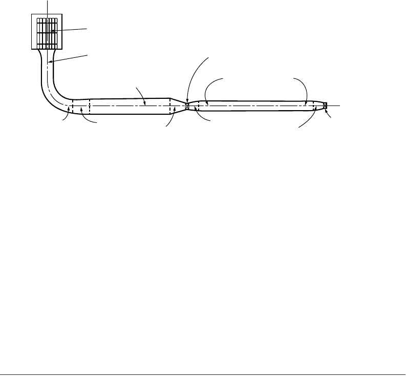
When the outlet is under pressure it performs as a system of pipes and fittings in series as shown in
Fig. 37.20. It typically includes trash racks, an inlet, conduits, expansions, contractions, bends, guard
gates that are usually fully open or fully closed for the purpose of isolating a segment of the system and
control valves for the regulation of the flow. The total head H
T
, the difference in elevation between the
reservoir and the centerline of the outlet, is used in overcoming the losses and producing the velocity
head at the exit
FIGURE 37.20 Outlet works pressure conduit. (Adapted from Department of the Interior, Bureau of Reclamation,
1987, Design of Small Dams Fig. 10.11, page 457, U.S. Government Printing Office, Denver, CO.)
Trashrack
Drop inlet
Upstream conduit - Area
Guard gate
Downstream conduit
Horizontal bend
Expanding transition
Contracting transition
Expanding transition
Contracting transition
Control valve
Bend
© 2003 by CRC Press LLC

37-20 The Civil Engineering Handbook, Second Edition
(37.17)
where Âh
i
= the sum of the applicable losses due to trash racks, entrance, bends, friction, expansion,
contraction, gate valves
h
v
= the exit velocity head
These losses are expressed as h
l
= KV
2
/(2g), except for the contraction and expansion losses which are
expressed as h
l
= K(V
1
2
– V
2
2
)/(2g). Appropriate values of the coefficient K may be found in Table 29.9,
Chapter 29 on Fundamentals of Hydraulics as well as in U.S. Department of the Interior, Bureau of
Reclamation (1987) or in handbooks (Brater et al., 1996). Additional information on design of trashracks
may be found in ASCE (1993).
When the outlet functions as an open channel, the flows are usually controlled by head gates. As the
channel can be nonprismatic, the flow profile is calculated by the procedure described in the section on
standard step method for gradually varied flow in nonprismatic channels (Chapter 30 on Open Channel
Hydraulics). An example of design can be found in U.S. Department of the Interior, Bureau of Reclama-
tion 1987. Guidelines for the design of high head gates that may be used in outlet works have been
reviewed by Sagar (1995). The experiences of outlet works in the UK have been reviewed by Scott (2000).
37.6 Energy Dissipation Structures
When spillways or outlet works flows reach the downstream river a large portion of the static head has
been converted into kinetic energy. Energy dissipation structures are therefore needed to prevent scour
at the toe of the dam or erosion in the receiving stream or damage to the adjacent structures. As the flow
from the spillway or the outlet works is usually supercritical, the hydraulic jump provides an efficient
way of dissipating energy as the flow goes from supercritical to subcritical. The ratio of the depth d
1
before the jump to the conjugate depth d
2
after the jump is
(37.18)
where F = V
1
/(gd
1
)
1/2
is the Froude number of the incoming flow and the head dissipated in the jump, h
j
, is
(37.19)
where V
1
and V
2
are the velocities before and after the jump.
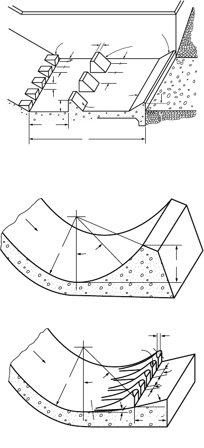
The US Bureau of Reclamation has developed several types of stilling basins to stabilize the position
of the jump and improve the energy dissipation. Figure 37.21 shows a Type III stilling basin for F > 4.5
and V
1
< 60 ft/s. The tailwater depth in the downstream channel is taken equal to the conjugate depth
d
2
. Similar information for other ranges of Froude numbers can be found in U.S. Department of the
Interior, Bureau of Reclamation (1987).
Usually the conjugate depth d
2
and the tailwater depth TW in the discharging stream cannot be matched
for all discharges. The elevation of the floor of the stilling pool can be set such that d
2
and TW match
at the maximum discharge. If TW > d
2
at lower discharges the conjugate depth d
2
can be raised by
widening the stilling basin and a closer fit between the two rating curves can be obtained. For some
rating curves the tailwater and the conjugate depth rating curves can be matched for an intermediate
discharge (see U.S. Department of the Interior, Bureau of Reclamation, 1987, p. 397). Whether the basin
is widened depends on hydraulic and economic considerations.
The submerged bucket dissipator can be used when the tailwater is too deep for the formation of a
hydraulic jump. There are two types: the solid bucket and the slotted bucket. Figure 37.22 shows the
geometry of these dissipators. The dissipation is due to the formation of two rollers rotating in opposite
Hhh
Tiv
=+
Â
dd F
21
2
12
12 1 8 1=+
()
-
È
Î
Í
˘
˚
˙
hdVgdVg
j
=+
()
-+
()
11
2
22
2
22
© 2003 by CRC Press LLC
Hydraulic Structures 37-21
directions. Curves for their design can be found in U.S. Department of the Interior, Bureau of Reclamation
(1987). The slotted bucket is the preferred design although the range of acceptable discharges is more
limited. Other types of smaller dissipation structures are the straight drop spillway, the slotted grating
dissipator and the impact type stilling basin. The latter type can be used with an open chute or a closed
conduit and its performance does not depend on the tailwater.
The high flow velocity and air mixing below spillways and plunge pools can result in a supersaturation
of nitrogen and oxygen in the water. This in turn can be a threat to anadromous fish. Geldert et al. (1998)
have developed relationships to predict the dissolved gasses below spillways and stilling basins. This
information can assist in the design and operation of such structures in order to mitigate high dissolved
gas concentrations below them.
FIGURE 37.21 USBR stilling basin type III for Froude numbers larger than 4.5 and incoming flow velocity less than
60 ft/s. (Source: U.S. Department of the Interior, Bureau of Reclamation, 1987 Design of Small Dams Fig 9.41, page 391.)
FIGURE 37.22 Submerged bucket dissipators.(Source U.S. Department of the Interior, Bureau of Reclamation, 1987,
Design of Small Dams. Fig 9.45, page 398 U.S. Government Printing Office, Denver, CO.)
L
h
4
s
3
= 0.75h
3
h
1
= d
1
s
1
= d
1
w
1
= d
1
w
3
= 0.75h
3
0.375h
3
0.5d
1
0.2h
3
h
3
0.8d
2
1:1 Slope
2:1 Slope
Chute blocks
End sill
Baffle blocks
TYPE III BASIN DIMENSIONS
R
45°
R
45°
1:1
0.6R
0.05R=radius
0.05R
0.125R
0.05R
(A) SOLID BUCKET
(B) SLOTTED BUCKET
0.5R
16°
8°
Flow
Flow
© 2003 by CRC Press LLC

37-22 The Civil Engineering Handbook, Second Edition
37.7 Diversion Structures
Construction of a dam across a perennial river generally requires the diversion of the flow so that the
site can be dewatered and the foundation excavation can proceed in the dry. The diversion works typically
include an upstream cofferdam, a downstream cofferdam and a conveyance structure. The upstream
cofferdam directs the flow towards the conveyance structure and the downstream cofferdam protects the
construction site from below. Cofferdams are temporary dams. Typically, they consist of circular cells
connected to one another. The periphery of the cells is made of flat-web steel sheetpilings that reach the
rock and provide effective water cutoff. The cells are filled with sand, gravel or a mix. The pressure of
the fill material produces a hoop tension in the interlocks that provides watertightness and structural
integrity. Free-standing cofferdams, without stabilizing inside berms, have been built to a height of 35 m
(115 ft) (Fetzer and Swatek, 1988). The conveyance structure can be a channel, or a single tunnel or
multiple tunnels. These conveyances can take the flow around the dam abutments or through the dam
itself. In some cases part of the conveyance structure can be integrated in the outlet works. The discharge
used for the diversion structures typically ranges from the 5-, 10-, 25- or the 50-year frequency flood
depending on the risk of flooding that can be tolerated. The higher frequencies are used if the site is
upstream of an urban area and if the cost of possible damage to completed work is important. Examples
of diversion structures can be found in U.S. Department of the Interior, Bureau of Reclamation (1987),
Swatek (1993) and Sentürk (1994).
37.8 Open Channel Transitions
Subcritical Transitions
Tr ansitions are needed to connect channels of different cross sections, for example, to connect a trape-
zoidal channel to a rectangular flume or to a circular conduit to cross over a valley on an aqueduct or
under a valley with an inverted siphon, respectively. These typically are contracting transitions. Likewise
the transition from a rectangular flume or a circular conduit to a trapezoidal channel usually is through
an expanding transition. Chow (1959) recommends an optimum maximum angle between the channel
axis and a line connecting the channel sides of 12.5
o
. The drop of water surface, Dy¢, for an inlet structure
is given by
(37.20)
and the rise in water surface, Dy¢, in an outlet transition is given by
(37.21)
where Dh
v
is the change in velocity head and the coefficients c
i
,
c
o
have the following values (Chow, 1959):
The following Bureau of Reclamation formula can be used for the preliminary estimates of freeboard
in channels less than 12 ft deep: F = [C y]
1/2
in which F is the freeboard, y is the depth, both in feet, and
C is a coefficient varying from 1.5 to 2.5 for channels with discharges varying from 20 to 3000 ft
3
/s,
respectively. There are two approaches to the design of transitions: (1) a free water surface is assumed
Tr ansition Type c
i
c
o
Warped 0.10 0.20
Cylinder quadrant 0.15 0.25
Simplified straight line 0.20 0.30
Straight line 0.30 0.50
Square ended 0.30+ 0.75
DD
¢
=+
()
ych
i
1
n
DD
¢
=-
()
ych
o
1
n
© 2003 by CRC Press LLC

Hydraulic Structures 37-23
(for example two reversed parabolas) and the depth is calculated for assumed width and side slope (Chow,
1959, p. 310–317 and French, 1985); or (2) the boundaries are set first and the surface is calculated (Vittal
and Chiranjeevi, 1983; French, 1985). Swamee and Basak (1991, 1992) have developed designs of rect-
angular and trapezoidal expansion transitions that minimize the head losses.
Supercritical Contractions
Contractions designed for subcritical flows will not function properly for supercritical flows. Generally,
with supercritical flow, wave patterns are formed in the contraction and propagate in the downstream
channel. Supercritical flow contractions are best designed for rectangular channels. The converging angles
on each side produce two oblique hydraulic jumps that makes an angle with the original flow direction.
A second pair of oblique jumps is created by the diverging angle at the downstream end of the contraction.
Ippen and Dawson (1951) devised a design such that the disturbances caused by the converging angles
are canceled by the disturbances caused by the diverging angles so that there is no wave pattern in the
channel downstream of the contraction. This design will function properly only for the specified Froude
number in the upstream channel. Additional details on the design of supercritical transitions can be
found in Ippen (1950), Chow (1959), Henderson (1966), French (1985) and Sturm (1985). Numerical
simulation of supercritical flow transitions has been discussed by Rahman and Chaudhry (1997).
37.9 Culverts
Flow Types
Culverts are short conduits that convey flows under a roadway or other embankment. They are generally
constructed of concrete or corrugated metal. Common shapes include circular, rectangular, elliptical,
and arch. Culverts can flow full or partly full. When the culvert flows full it functions as a pipe under
pressure. When it flows partly full it functions as an open channel and the flow can be subcritical, critical
or supercritical. (See Chapter 30, “Open Channel Hydraulics”.) A culvert operates either under inlet or
outlet control. If the culvert barrel has greater capacity than the inlet, then the culvert functions under
inlet control. Conversely, if the barrel has less capacity than the inlet, the culvert operates under outlet
control. Figures 37.23 and 37.24 illustrate inlet and outlet control flows, respectively. Partly full flow can
occur with inlet control or with outlet control.
When operating under inlet control the flow becomes critical just inside the entrance and the flow is
supercritical through the length of the culvert if the outlet is unsubmerged; if the outlet is submerged a
hydraulic jump forms in the barrel. For low unsubmerged headwater the entrance of the culvert operates
as a weir (Eq. [37.10]). When the headwaters submerge the entrance it performs as an orifice (Eq. [37.12]).
From tests by the National Bureau of Standards, performed for the Bureau of Public Roads (now Federal
Highway Administration), equations have been obtained to calculate the headwater above the inlet invert,
for unsubmerged and submerged inlet control (Normann et al., 1985). These equations can be presented
in a regression form that gives a direct solution for the inlet head given the discharge, the span and the
rise of the culvert for the several culvert types. The equation and a table of regression coefficients can be
found in U.S Federal Highway Administration (1999).
When operating under outlet control, for a full flow condition the total loss, H
L
, through the conduit is
(37.22)
where k
e
= an entrance loss coefficient
L = the length of the culvert
R = the hydraulic radius
n =Manning’s roughness coefficient
V = the flow velocity
HkgnLKRVg
Le M
=++
()
[]
12 2
221332.
© 2003 by CRC Press LLC
37-24 The Civil Engineering Handbook, Second Edition
K
M
has a value of 1 for metric units and 1.486 for customary English units (See Chapter 30, “Open
Channel Hydraulics,” Section 30.3).
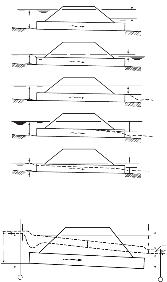
For a full flow condition the energy and hydraulic grade line are shown in Fig. 37.25 and the relation
between points at the free surface upstream and downstream of the culvert is
(37.23)
where HW
o
= the headwater depth about the outlet invert
V
u
= the upstream velocity of approach
TW = the tailwater depth above the outlet invert
V
d
= the downstream velocity
H
L
= the total loss through the conduit given in the preceding equation
For further details on the hydraulics and design of culverts see, for example, Tuncock and Mays (2001).
Inlets
For culverts operating under inlet control, the performance can be improved by reducing the contraction
at the inlet and by increasing the effective head. These objectives can be achieved with tapered inlets.
The simplest design is the side tapered inlet in which the side walls are flared between the throat and the
face resulting in an enlarged face section. In addition, the effective head can be increased by depressing
the inlet. This can be achieved by an upstream depression between the wingwalls or a sump upstream
of the face section. A more elaborate design is the slope tapered inlet that has flared sidewalls. A fall is
incorporated between the throat and the face sections, (Normann et al, 1985).
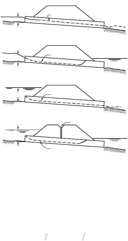
FIGURE 37.23 Types of inlet control: (A) inlet and outlet outlet unsubmerged, critical flow at entrance, supercritical
flow along barrel, (B) inlet unsubmerged and outlet submerged, critical flow at entrance and supercritical flow
upstream of hydraulic jump in culvert, (c) inlet submerged, outlet unsubmerged, critical depth at entrance and
supercritical flow along barrel, (D) inlet and outlet submerged, similar to (B) with hydraulic jump in culvert. (Source:
Normann et al. 1985.)
HW
Water Surface
A
HW
Water Surface
B
HW
Water Surface
C
HW
Water Surface
D
Median Drain
HW V g TW V g H
ou d L
+
()
=+
()
+
22
22
© 2003 by CRC Press LLC
Hydraulic Structures 37-25
Sedimentation and Scour
Special consideration must be given to the transport of sediments. Low flow velocities within the culvert
may result in deposition of sediments, whereas high velocities may produce erosion at the outlet of the
culvert. For further details on sediment transport see Chapter 35, “Sediment Transport in Open Channels”
and Yang (1996). Protection against scour include cutoff walls, riprap armoring and energy dissipators.
These protection devices are used if the outlet velocities are larger than 1.3 times the natural stream
velocity, between 2.3 and 2.5 or greater than 2.5 times the natural stream velocity, respectively (Tuncock
and Mays, 2001).
FIGURE 37.24 Types of outlet control: (A) inlet and outlet submerged, pipe flow, (B) inlet unsubmerged and outlet
submerged, with surface drop at the entrance and contraction, (c) inlet submerged, pipe flow along barrel, no
tailwater, (D) inlet submerged and outlet unsubmerged, outlet depth grater than critical, (E) inlet and outlet
unsubmerged, subcritical flow over entire length, critical condition at outlet. (Source: Normann et al. 1985.)
FIGURE 37.25 Energy and hydraulic grade line for full flow condition (Source: Normann et al. Hydraulic Design of
Highway Culverts. 1985. Fig. III-8, p.36 Federal Highway Administration Report No. FHWA-IP-85–15.)
HW
W.S.
Water Surface
A
H
HW
W.S.
B
H
HW
W.S.
C
H
HW
W.S.
D
H
HW
W.S.
E
H
Section
1
Section
2
E.G.L.
H.G.L.
v
2
/2g
v
2
u
/2g
v
2
d
2g
H
HW
HW
0
TW
H
e
H
f
H
o
© 2003 by CRC Press LLC

37-26 The Civil Engineering Handbook, Second Edition
Software
The principal public domain computer program for the hydraulic design and analysis of culverts is: the
interactive program HY8 that is part of the HYDRAIN (U.S. Federal Highway Administration, 1999), an
integrated drainage design computer system. HY8 consists of four modules: (1) culvert analysis and
design, (2) hydrograph generation,( 3) routing, and (4) energy dissipation. HYDRAIN (version 6.1) can
be downloaded from http://www.fha.dot.gov/bridge/hydrain.htm. The software package HEC-RAS, River
Analysis System, developed by the US. Army Corps of Engineers, Hydrologic Engineering Center (2001)
is a comprehensive suite of computer programs for water surface and river hydraulics calculations and
includes hydraulics of bridges and culvert openings. HEC-RAS can be downloaded from http://www.wrc-
hec.usace.army.mil/. These programs are discussed in more detail in Chapter 38, “Simulation in Hydrau-
lics and Hydrology”.
37.10 Bridge Constrictions
Backwater and Discharge Approaches
The hydraulics of bridges can be approached from the point of view of the highway engineer or from
that of the hydrologist. The highway engineer is concerned with the amount of backwater created by a
bridge constriction. Approach embankments are often extended in the flood plain to reduce the span of
the bridge proper and thus decrease the cost of bridge crossings. The flow is thus forced to pass through
a constriction that may produce a backwater. In contrast the hydrologist is concerned with the indirect
determination of the discharge of a large flood from high water mark observations and from the geometry
of the constriction. Indirect methods of discharge determination are needed when the flow rate is beyond
the range of the rating curves at gaging stations.
Flow Types
Three different types of flow can occur at a bridge constriction. The first occurs when the flow is subcritical
both in the stream and through the constriction. This is the flow type most generally encountered,
illustrated in Fig. 37.26 and is discussed below. In the second type the flow is subcritical upstream of the
bridge but goes through critical in the constriction. The flow can then immediately return to subcritical
as it exits the constriction or the water surface can dip below the critical depth downstream of the
constriction and then return to its normal depth through a hydraulic jump. Finally, the third type occurs
when the flow is supercritical through both the stream and the constriction.
Backwater Computation
The backwater superelevation, h
*
1
, upstream of a constriction with subcritical flow is given by Bradley
(1978)
(37.24)
where K* = the backwater coefficient
A
n2
= the gross water area in constriction measured below normal stage
V
n2
= Q/A
n2
is the average velocity in the constriction
A
4
= the area at section 4 where the normal depth is reestablished
A
1
= the water area at section 1
including that produced by the backwater
a
1
and a
2
= the kinetic energy corrections factors at sections 1 and 2, respectively (See Eq. [29.11] in
Chapter 29, “Fundamentals of Hydraulics”)
hK V g AA AA V g
nnnn122
2
124
2
21
2
2
2
22
**
=
()
+
()
-
()
[]
()
aa
© 2003 by CRC Press LLC
