Wai-Fah Chen.The Civil Engineering Handbook
Подождите немного. Документ загружается.

Hydraulic Structures 37-27
a
1
can be approximated as a
1
= Sqv
2
/(QV
1
2
) where q and v are the discharge and velocity in subsections
of section1, respectively. Similarly a
2
can be approximated for section 2. In Fig. 37.27, the basic backwater
coefficient K
b
is given as a function of the bridge opening ratio, M = Q
b
/Q, where Q
b
is the flow in the
portion of channel
within the projected length of the bridge (Fig.37.26) and Q is the total discharge.
Incremental
coefficients to account for the effects of the piers, opening eccentricity, skewed crossing, dual
bridges, bridge girder submergence, and backwater in the stream can be found in Bradley (1978). The
sum of K
b
and the incremental coefficients yields K
*
.
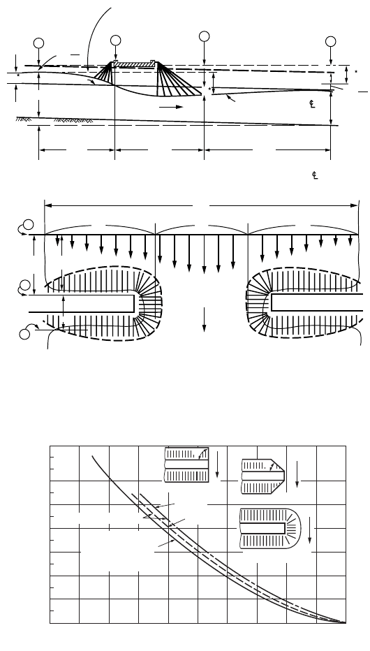
FIGURE 37.26 Normal bridge crossing with spillthrough abutments. (Source: Bradley, 1978, Hydraulics of Bridges.
FIGURE 3 p. 7, Hydraulic Series No.1, Federal Highway Administration.)
FIGURE 37.27 Backwater coefficient for wingwall (WW) and spillthrough abutments. (Source: Bradley, 1978,
Hydraulics of Bridges, Fig 6, p. 14, Hydraulic Series No.1, Federal Highway Administration.)
W
Q
c
Q
b
S
0
Q
a
1
2
3
SECT.
1
SECT.
2
SECT.
3
SECT.
4
SECT.
SECT.
SECT.
L
1-2
L
1-2
L
2-3
L
3-4
L
2-3
L*
Plan at Bridge
Flow
Actual W.S. on
Normal W.S.
Flow
W.S. Along bank
h
1
h
b
α
4
y
1
y
4
∆h
Profile on Stream
V
2
4
2g
( )
α
1
V
2
1
2g
( )
h
3
L
1-4
h
r
s
0
90°
45°
45°Wingwall
90°Wingwall
90°WW
30°WW
Spillthrough
All spill through
or 45° and 60° WW
abutments over
200 ft. in length
For lengths up to 200 ft.
0
0
0.4
0.8
1.2
1.6
2.0
2.4
2.8
0.1 0.2 0.3 0.4 0.5
M
K
b
0.6 0.7 0.8 0.9 1.0
© 2003 by CRC Press LLC
37-28 The Civil Engineering Handbook, Second Edition
Discharge Estimation
The discharge, Q, through a bridge constriction, under subcritical flow condition, can be calculated from
Chow (1959)
(37.25)
where C =a discharge coefficient
A
3
= the flow area at section 3
Dh = the drop in water surface between section 1 and section 3
V
1
= the mean velocity at section 1
h
f
= the head loss between sections 1 and 3
This loss is calculated from
(37.26)
where L
a
= the approach length from section 1 to the upstream face of the abutment
L = the length of the contraction
K
1
= (K
M
/n) A
1
R
1
2/3
is the conveyance at section 1 in which K
M
= 1 for metric units and K
M
=
1.486 for customary English Units
Similarly, K
3
is the conveyance at section 3. The discharge coefficient, C, depends on the shape of the
abutment, the ratio of the contraction length to the contraction width, L/b, and the contraction ratio
m = 1 – K
b/
K
1
, where b is the constriction width, K
b
is the conveyance of the contracted section and K
1
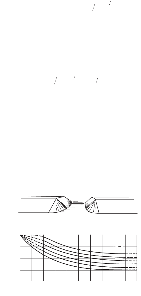
is the conveyance of the approach section 1. Figure 37.28 gives the base discharge coefficient for the bridge
opening with spillthrough abutments. Chow (1959) and Kindsvater et al. (1953) give curves for deter-
mination of the discharge coefficient for different abutment types and multiplicative correction factors
to account for the effects of the Froude number, the rounding and chamfering of the abutment, the
skewness and eccentricity of the bridge, the possible submergence of the bridge girders, the piers and piles.
FIGURE 37.28 Discharge coefficient for spillthrough abutment bridge opening. (Source: Kindsvater, C.E., Carter,
R.W. and Tracy, H.J., Computation of Peak Discharge at Contractions, U.S. Geological Survey, Circular No. 284.)
QCA g hh V g
f
=-+
()
()
[]
311
2
12
22Da
hLQKK LQK
fa
=
()
[]
+
[]
13
12
2
3
2
Type III
m = Per cent of channel contraction
C = Coefficient of discharge
0.60
0.70
0.80
0.90
1.00
0102030405060708090100
L
b
1.00
0.80
0.40
0.20
0
0.60
© 2003 by CRC Press LLC

Hydraulic Structures 37-29
Scour
The previous discussion assumes that the channel is rigid, that is it does not aggrade nor degrade.
However, long-term stream bed degradation and local scour may take place. Aggradation occurs when
the sediment load supplied to a river reach exceeds its transport capacity. Aggradation can cause a
reduction of bridge waterway openings. This in turn can result in increased upstream flooding and
increased scour at the contraction (Johnson et al. 2001). Scour can occur during rapid flow events, when
sediments are transported by the currents eventually undermining bridge pier foundations. Erosion and
deposition can occur during the same flood event. (See Chapter 35, “Sediment Transport in Open
Channels”).
The Federal Highway Administration current practice in the determination of scour at bridges can be
found in Richardson and Davis, (1995) and has been summarized by Tuncock and Mays (2001). This is
a deterministic approach. Instead, Johnson and Dock (1998) propose a probabilistic approach for deter-
mining the likelihood of various scour depths for storm events of specified return periods. Monitoring
scour is difficult; however, frequency modulated–continuous wave (FM-CW) reflectometry has potential
for continuous monitoring of sediment depths (Yankielun and Zabilansky, 2000).
Software
The principal public domain computer programs for hydraulics of bridges are: HEC-RAS and WSPRO.
The software package HEC-RAS, River Analysis System, developed by the US. Army Corps of Engineers,
Hydrologic Engineering Center (2001), is a comprehensive suite of computer programs for water surface
and river hydraulics calculations and includes hydraulics of bridges and culvert openings. HEC-RAS can
be downloaded from http://www.wrc-hec.usace.army.mil. WSPRO is part of the HYDRAIN, an integrated
drainage design computer system (U.S. Federal Highway Administration, 1999). It performs backwater
calculations by the standard step method (see Chapter 30, “Open Channel Hydraulics”). HYDRAIN can
be downloaded from http://www.fhwa.dot.gov/bridge/hydrain.htm. These programs are discussed in
more detail in Chapter 38, “Simulation in Hydraulics and Hydrology.”
37.11 Pipes
The hydraulics of flow in pipes is discussed in Chapter 29, “Fundamentals of Hydraulics.”
Networks
For pipe network calculations it is convenient to express the friction loss, h
L
, in a pipe by an equation of
the form
(37.27)
where K includes the effects of the pipe diameter, length and roughness as well as the fluid viscosity.
For the Darcy-Weisbach formula (Eq. [29.21] in Chapter 29, “Fundamentals of Hydraulics”)
(37.28)
where L = the pipe length
D = the diameter
Q = the discharge
The friction factor f is obtained from the Moody diagram (see Chapter 29). The formula is valid for
consistent metric and English units. For the Hazen-Williams formula
hKQ
L
n
=
KfL gD n=
()
=82
25
p and
© 2003 by CRC Press LLC

37-30 The Civil Engineering Handbook, Second Edition
(37.29)
where C
u
= 10.654 for metric units and C
u
= 4.727 for English units
C = the Hazen-Williams coefficient, typical values of which are given in Table 37.1
Two basic relationships must be satisfied in a network: the continuity or conservation of mass at each
junction and the energy relationship around any closed loop. The continuity relationship requires that
the sum of the flows entering a node be equal to the sum of the flows leaving it. The energy relationship
requires that the algebraic sum of the head losses in any loop be zero using an appropriate sign convention,
for example flows are positive in the counterclockwise direction. The same sign convention applies to all
loops of the network. Minor losses due to fittings and valves, etc. and energy gains due to pumps are
included in the appropriate segments.
The first systematic numerical procedure for the calculation of the flows of liquids in pipe networks
was proposed by Hardy Cross (1936). It includes the following steps: (1) assume a discharge in each pipe,
Q
g
, so that the continuity requirement is satisfied at each node, (2) for each pipe loop calculate a first
order correction to the discharge
(37.30)
TABLE 37.1 Williams-Hazen Coefficients
Pipe Material Condition Size C
Cast Iron New all 130
5 years old ≥ 12 in. 120
8 in. 119
4 in. 118
10 years old ≥ 24 in. 113
12 in. 111
4 in. 107
20 years old ≥24 in. 100
12 in. 96
4 in. 89
30 years old ≥30 in. 90
16 in. 87
4 in. 75
40 years old ≥ 30 in. 83
16 in. 80
4 in. 64
50 years old ≥ 40 in. 77
24 in. 74
4 in. 55
We lded Steel Same as Cast iron 5 years older
Riveted Steel Same as cast Iron 10 years older
Wood Stave Average value regardless of age 120
Concrete or concrete lined Large sizes, good workmanship, steel forms 140
Large sizes, good workmanship, wooden forms 120
Centrifugally spun 135
Vitrified In good condition 110
Plastic or drawn tubing 150
Source:Wood, D.J., 1980. Computer Analysis of Flow in Pipe Networks Including Extended
Period of Simulation, User’s Manual, Office of Continuing Education and Extension of the
College of Engineering, University of Kentucky, Lexington, KY. With permission.
KCC LD n
u
==
--1 852 4 87
1 852
..
. and
DS SQKQxKQ
g
x
g
x
=-
[]
-1
© 2003 by CRC Press LLC
Hydraulic Structures 37-31
taking into account the sign convention in the numerator of the right hand side,(3) in each pipe loop
add the corrections algebraically to flow in each pipe (note that a pipe that is common to two loops has
different signs depending upon which loop is considered and this pipe will receive two corrections),
(4) with Q
g
being the new flows, calculate a new correction DQ for each loop, (5) in each loop add the
correction algebraically to each pipe, (6) repeat steps 4 and 5 until the correction becomes sufficiently
small. An example involving 7 pipes, 2 reservoirs, and 1 pump can be found in Lansey and Mays (1999).
The main advantages of the Hardy cross method are that it provides an understanding of the procedure
and that the calculations can be done by hand for small networks. Its main limitation is that it solves
the equations one at a time. More recent methods use more efficient numerical techniques such as the
linear theory, the Newton-Raphson method or the gradient method to solve the large system of equations
for the nodes and loops. For large networks computer programs are used. (see section on software later
in this chapter). For further discussion on pipe networks see, for example, Lansey and Mays (1999).
Hydraulic Transients and Water Hammer
A hydraulic transient is a situation where conditions, such as flow velocity and pressure, are time varying.
Some of the common conditions creating a transient are: a change in a valve opening; operation of check
valves or pressure relief valves; starting or stopping of pumps; changes of power demand on hydraulic
turbines; pipe break; trapped air in pipeline; filling or flushing of pipes, etc. Large and rapid changes in
velocity can create high transient pressures. If the pipe is not designed to withstand the high transient
pressures or if controlling devices are not included to limit the increase in pressure head, damage
(including rupture) can occur to the pipe or to the connected equipment and machinery.
When the flow of a liquid in a pipe is stopped abruptly due to a rapid valve closure, for example, the
kinetic energy is transformed into elastic energy and a train of positive and negative pressure waves travels
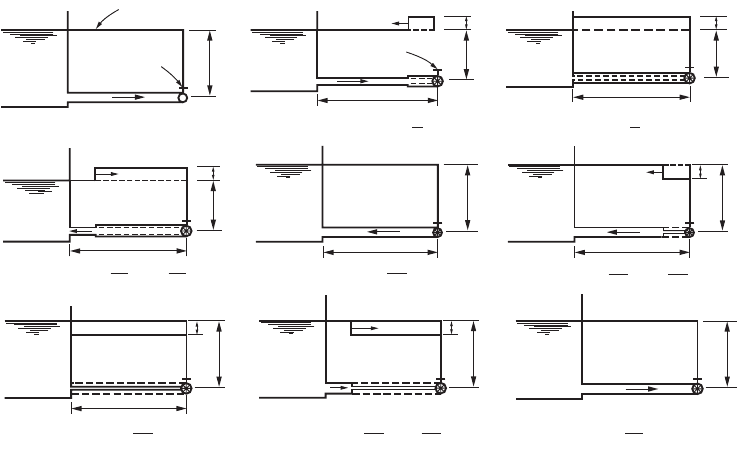
up and down the pipe until the energy is dissipated by friction. (Fig. 37.29). When the liquid is water
this is known as water hammer because the transient noise in small pipes sounds as if it is being hit by
a hammer. The elasticity of the liquid and of the pipe material need to be taken into account. Consider
the elastic properties of the water and the pipe: the bulk modulus of the liquid, E,(about 3 ¥ 10
5
psi or
FIGURE 37.29 Water hammer cycle due to instantaneous valve closure.
Valve open
V=V
0
Hydraulic grade line
Reservoir
H
0
Valve closed
V=V
0
V=0
H
0
∆H
(a) t ≤ 0
(b) 0 < t <
L
C
∆H
C
C
L
L
V=0
H
0
∆H
(c) t =
L
C
(e) t =
2L
C
(g) t =
3L
C
L
V=−V
0
H
0
V=−V
0
V=0
H
0
∆H
(d) < t <
2L
C
3L
C
C
L
(i) t =
4L
C
V=V
0
H
0
L
< t <
(f)
2L
C
3L
C
V=−V
0
V=0
H
0
∆H
C
< t <
(f)
3L
C
4L
C
V=V
0
V=0
H
0
∆H
L
V=0
H
0
© 2003 by CRC Press LLC

37-32 The Civil Engineering Handbook, Second Edition
2 GN/m
2
for water) and the modulus of elasticity of the pipe material E
p
(about 30 ¥ 10
6
psi or 200 GN/m
2
for steel). The velocity or celerity, c, of the pressure wave is given by
(
37.31)
in which r is the fluid density, t
p
is the thickness of the pipe wall and D is the pipe diameter.
For an initial flow velocity V, the rise in pressure head due to the sudden valve closure is obtained
from the momentum principle as
(37.32)
This is the pressure head obtained when the time of closure of the valve, t
c
, is less than the time for
the round trip travel of the pressure wave 2L/c. For a longer closing time, t, the pressure head can be
approximated as (t/t
c
) DH. However, more accurate results can be obtained by numerical integration of
the transient flow equations. (Morris and Wiggert (1972), Wylie and Streeter (1993), and Borg (1993).
Figure 37.29 illustrates the pressure wave propagation without friction. Diagram (a) shows the initial
steady state hydraulic grade line and velocity V
0
with the valve open. When the valve is suddenly closed
the head rise Dh is calculated by Eq. (37.32) and the pressure wave travels upstream with the celerity c
calculated from Eq. (37.31). Diagram (b) illustrates the condition for 0< t < L/c. Behind the wave the
velocity is zero, the pressure is increased, and the pipes expands. The mass of water entering the pipe is
equal to the increased volume of the pipe plus the added mass stored due to the increased water density.
When t = L/c the pressure wave arrives at the reservoir as shown in diagram (c). The pressure in the pipe
is H
0
+ DH, the velocity is zero and the increased pressure exists all along the pipe. This is a non-
equilibrium situation, the compressed fluid then flows from the pipe into the reservoir at a velocity –V
o
and the reflected pressure wave recedes. The cycle continues as shown in diagrams (e) to (i). For an in-
depth treatment of water hammer see, for example, Martin (1999), Wylie and Streeter (1993), Borg
(1993), Rich (1963), Parmakian (1963), Chaudhry (1987), and Jaeger (1977). There are computer pro-
grams for the analysis of water hammer (see section on software).
Surge Protection and Surge Tanks
There are two types of transient events that need to be controlled: the downsurge or low pressure event
that occurs with pump power failure and the upsurge or high pressure event caused by the closure of a
downstream valve. Surge control protection devices include several types of valves such as check valves
and surge relief valves (Martin, 1999). Another device is the surge tank or standpipe. A surge tank is a
vertical tank connected to the pipeline that typically extends above the maximum grade line. The surge
tank diameter is substantially larger than that of the pipe to avoid spilling. The standpipe has a smaller
diameter, possibly less than the pipe, and is used if spillage can be allowed. Normally the standpipe is
designed high enough so as to avoid spillage during normal shutdown.
Surge tanks are standpipes that are installed in large piping systems to relieve the water hammer
pressure when a valve is suddenly closed and to provide a reserve of liquid when a valve is suddenly
opened. In hydropower installations they are located close to the turbine gates. In pumping installations
they are located on the discharge side of the pumps to protect against low pressures during stoppage of
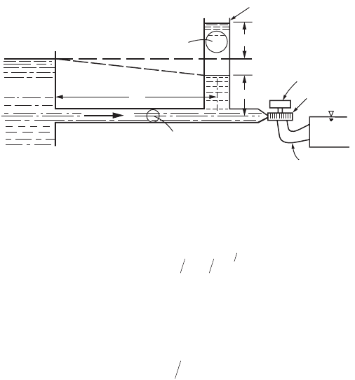
the pumps. A simple surge tank is connected directly to the penstock (Fig. 37.30). An orifice surge tank
has an orifice in the connection between the tank and the pipe, often with a larger coefficient of discharge
for flow out of the tank. A differential surge tank consists of two concentric surge tanks, the inner one
is usually a simple surge tank that provides a rapid response but has a small volume. The outer and larger
tank is usually an orifice tank.
Consider a horizontal pipe of cross-sectional area A and length L between a reservoir and a surge tank
of cross section S, in which the instantaneous water level is at an elevation y above that of the reservoir
cE EDEt
pp
2
1
1=
()
+
()
[]
-
r
DDHp Vcg==g
© 2003 by CRC Press LLC
Hydraulic Structures 37-33
(Fig. 37.30). V
o
is the steady state flow velocity in the pipe. At the time of closure the surge water elevation
obtained neglecting friction, is
(37.33)
If the pipe is fairly long the friction should be included. This results in a differential equation that
requires numerical solution (Morris and Wiggert, 1972). The minimum cross-sectional area required for
stability of the surge tank derived by Thoma and cited by Rich (1963) and by Coleman et al. (1999) is
(37.34)
where k = H
l
/V
2
is the ratio of the head loss between the reservoir and the surge tank to the square
of the flow velocity in the conduit
H
s
= the steady state head in the surge tank
This area is multiplied by a minimum safety factor of 1.5 for simple surge tanks and 1.25 for orifice
surge tanks, to obtain reasonably fast damping of the water oscillations according to Coleman et al.
(1999), Borg (1993) and Rich (1963). For a more detailed treatment of surge tanks and other surge
suppressing devices see Coleman et al. (1999), Wylie and Streeter (1993), Borg (1993), Rich (1963),
Chaudhry (1987), and Jaeger (1977).
Valves
Valves are used to regulate the flow and pressure in pipes and to perform many other functions. These
include prevention of reverse flow through pumps, protection of pipes and pumps from overpressurization,
prevention of transients etc. Head loss coefficients for several types of valves are shown in Table 29.9
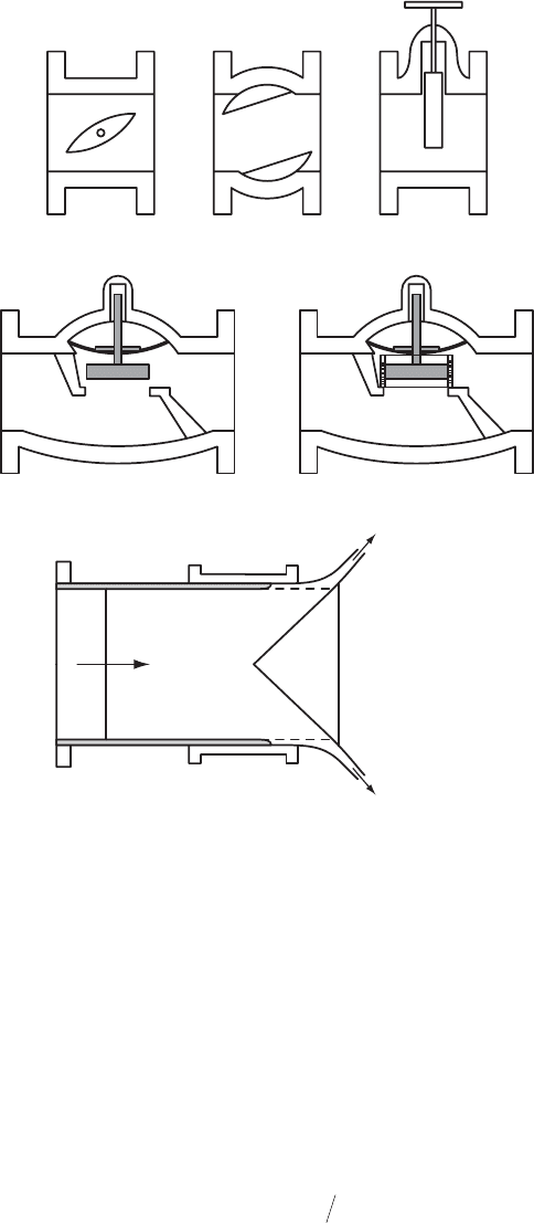
(Chapter 29, “Fundamental of Hydraulics”). Some valves are used to prevent flow in certain sections of
pipe. They are normally fully open or fully closed. The gate valves are of this type. Other valves are used
to control the flow. Examples of control valves are the butterfly valve, the cone, ball and plug valves, the
globe valves. Howell-Bunger valves and hollow jet valves are free discharge valves used to release water
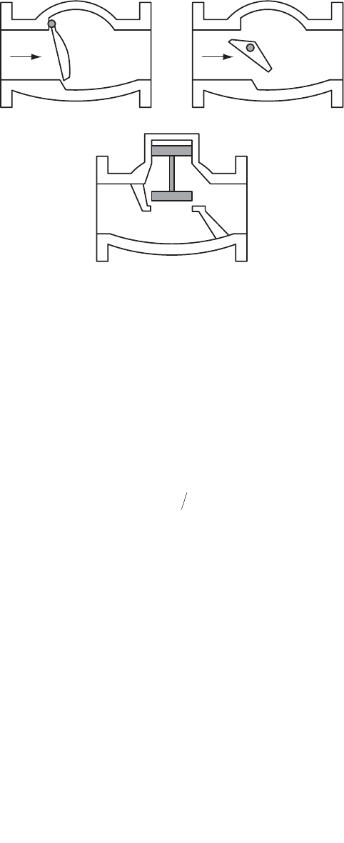
from reservoirs, for aerating water, for flood control or irrigation. Check valves are used to prevent reversal
of the flow. Figures 37.31 and 37.32 show simplified sketches of several types of control and check valves.
Cavitation
Cavitation is a process similar to boiling. It consists of rapid vaporization and condensation. For boiling,
vapor cavities are formed due to temperature increase. The vapor cavities rise to the surface and explode
releasing vapor to the atmosphere. For cavitation, the vapor cavities are formed when the fluid pressure
drops below the vapor pressure. The cavity will collapse if there is a local pressure in the cavitation region
FIGURE 37.30 Simple surge tank.
Tailwater
Draft tube
Generator
Turbine
Y
S
L
V
A
Static level
Reservoir
H
1
H
s
Hydraulic grade line
Surge tank
yVASLg
omax
=
()()
[]
12
SAL gkH
s
=
()
()
2
© 2003 by CRC Press LLC
37-34 The Civil Engineering Handbook, Second Edition
that is greater than the vapor pressure. In a venturi, for example, the pressure is minimum at the throat
where the cavity may form and collapse occurs as the cavity moves from the throat into the diffuser
where the pressure increases with distance. The shock waves produced by the collapsing cavities produce
pressure fluctuations that can induce vibration of the system. Cavitation creates noise. The noise created
by cavitating valves can be quite intense, varying from a hissing or crackling sound to loud roars with
intermittent explosions. The collapse of cavities close to solid boundaries can causes considerable damage
to almost any surface. It also causes corrosion of metal surfaces. Cavitation can also occur in hydraulic
machinery reducing its efficiency and damaging the impellers. The onset of cavitation can be expressed
by a cavitation number. For valves the cavitation number s is generally defined as
(37.35)
where p
d
= the pressure downstream (10 diameters)
p
b
= the barometric pressure
p
va
= the absolute vapor pressure
Dp = the net pressure drop
FIGURE 37.31 Schematic of typical control valves. (Source: Tullis, J.P., 1989, Hydraulics of Pipelines, Pumps, Valves,
Cavitation, Transients. John Wiley & Sons, New York, NY. Fig 4.1 p.83.)
Butterfly Cone and Ball Gate
Globe
fluid press
Globe with cavitation trim
fluid press
orifices
Howell Bunger
Flow
rigid cone
free dischrage
free dischrage
s= + -
()
ppp p
dbva
D
© 2003 by CRC Press LLC
Hydraulic Structures 37-35
The cavitation parameter for pumps is discussed in the section on pumps. The vapor pressure head
of water as a function of temperature is given in Chapter 29, “Fundamentals of Hydraulics,” Tables 29.1
and 29.2. Tullis (1989) gives experimental values of the cavitation parameter for several types of valves
and for several intensities of cavitation.
Forces on Pipes and Temperature Stresses
The fluid pressure in a pipe creates a circumferential tension stress called hoop stress given by
(37.36)
where p = the pressure (static plus water hammer)
D = the inside diameter
t = the thickness of the pipe wall
Unsupported pipe segments act as beams. The loads include the weight of the pipe, the weight of the
fluid and any superimposed load. Forces on pipe bends and anchor blocks are obtained by the momentum
equation as illustrated in Chapter 29 (Application 29.8).
Buried pipes must support the loads due to gravity earth forces and live loads. Load and supporting
strength depend on installation conditions. Design details and specifications can be found in ACI, ASTM,
AASHTO or FHWA specifications and industry manuals. ASCE (1992) Manual of Practice 77 (Chapter
14 on structural requirements) gives a good state-of-the-art review.
For concentrated and distributed loads superimposed on buried pipes the reader is referred to the
AASHTO Code, the Portland Cement Association 1951) and the American Concrete Pipe Association
(1988) for wheel loads, as well as to ASCE (1992) for a discussion of the Boussinesq theory for concen-
trated loads.
A temperature change DT on a pipe of modulus of elasticity E and coefficient of thermal expansion
a will induce a longitudinal stress, assuming fixed ends, given by
(37.37)
For steel approximate values of the physical constants are E = 30 ¥ 10
6
psi and a = 6.5 ¥ 10
–6
°F.
–1
FIGURE 37.32 Schematic of typical check valves. (Source: Tul lis J.P., 1989, Hydraulics of Pipelines, Pumps, Valves,
Cavitation, Transients. John Wiley & Sons, Nrew York, NY. Fig 4.10, p.112.)
Swing check
Flow
Tilting disc check
Flow
Lift check
spD t=
()()
2
sa= ETD
© 2003 by CRC Press LLC

37-36 The Civil Engineering Handbook, Second Edition
Software
EPANET, developed by the U.S. Environmental Protection Agency (2000), is a public domain software.
It performs extended period simulation of hydraulics and water quality behavior in a pressurized pipe
network. In the hydraulic analysis it places no limit on the size of the network, computes friction headloss
using the Hazen-Williams, Darcy-Weisbach or Chézy-Manning formulas, includes minor losses, constant
or variable speed pumps, variable geometry surge tanks, etc. It uses a gradient algorithm for the solution
of the hydraulic equations. In addition to the hydraulic modeling, EPANET models the movement of
non-reactive tracer material through the network over time, models the movement and fate of a reactive
material as it grows or decays (e.g., chlorine residual) with time, models the age of water throughout a
network, tracks the percent of flow from a given node reaching all other nodes over time, etc. EPANET 2
can be downloaded from http://www.epa.gov/ORD/NRMRL/wswrd/epanet.html.
KYPIPE, is a computer program for the solution of pipe networks developed at the University of
Kentucky (Wood, 1980). It uses a Newton method for the solution of the hydraulic equations.
FORTRAN computer programs for water hammer analysis can be found in Wylie and Streeter (1993)
and in Chaudhry (1987). A FORTRAN program for water level oscillations in a simple surge tank is
given in Chaudhry (1987). Tabular presentations of the numerical integration of the unsteady flow
equations that can be adapted to spread sheet software such as EXCEL, LOTUS, QUATTRO PRO, etc.
can be found in Morris and Wiggert (1972, p. 335) for water hammer and in Rich (1963) for water
hammer, surge tanks and stability analysis.
37.12 Pumps
Centrifugal Pumps
Centrifugal pumps are those most commonly used in civil engineering applications. The rotating part
of the centrifugal pump is the impeller. It consists of blades or vanes attached to the hub. If the blades
are enclosed by plates or shrouds on the top and bottom sides, the impeller is closed. Impellers without
shrouds (i.e., open impellers) are less prone to become clogged when the liquids contain suspended
matter. Closed impellers, however are more efficient. In radial flow impellers the fluid is forced outward
in the radial direction, which is perpendicular to the axis (see Fig. 37.33), while in axial flow impellers
the fluid exits along the axis. In the mixed flow pumps the impeller imparts velocities that have both
radial and axial components. The flow exits from the impeller into a casing called the volute. Centrifugal
pumps can be single stage or multistage. Deep well pumps often are multistage, which is equivalent to
several stages or impellers in series so that the total head generated by the pump is the sum of the heads
imparted to the fluid at each stage.
The impeller exerts a torque on the fluid. This torque can be calculated as the change in angular
momentum. This is obtained by multiplying the terms of the momentum equation (Eq. [29.15])) by the
lever arm r, to yield
(37.38)
where V
t1
and V
t2
= the tangential components of the flow velocities at the entrance and at the exit of
the impeller, respectively
r
1
and r
2
= the radii at the entrance and exit of the vane
If e is the pump efficiency, then the power to be supplied to the pump shaft by the motor is (1HP =
550 ft.lb/s in English units and 1kW = 1000 N.m/s in SI units)
(37.39)
TQVrVr
tt
=-
()
r
22 11
HP T e Q H e kW T e Q H e
pp
=
()( )
=
()
()
==wg wg550 550 1000 1000;
© 2003 by CRC Press LLC
