Wai-Fah Chen.The Civil Engineering Handbook
Подождите немного. Документ загружается.

Theory and Analysis of Structures 47-11
(47.9)
in which M
A
, M
B
, and M
C
are the hogging moment at supports A, B, and C, respectively, of two adjacent
spans of length L
1
and L
2
(Fig. 47.9); A
1
and A
2
are the area of bending moment diagrams produced by
the vertical loads on the simple spans AB and BC, respectively; x
1
is the centroid of A
1
from A; and x
2
is
the distance of the centroid of A
2
from C. If the beam section is constant within a span but remains
different for each of the spans Eq. (47.9) can be written as
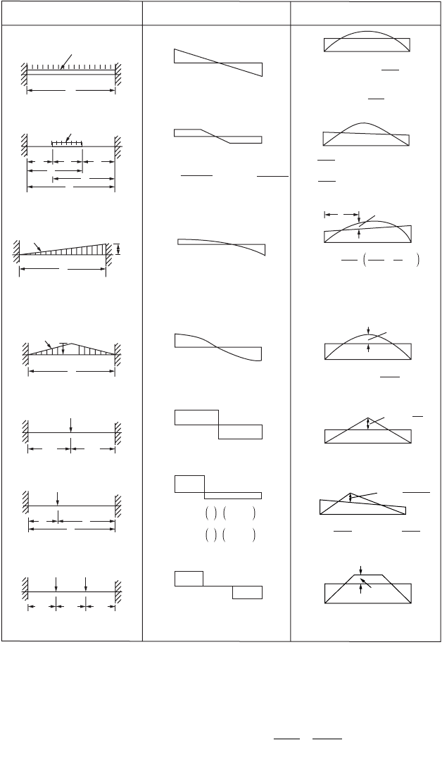
FIGURE 47.8 Shear force and bending moment diagrams for built-up beams subjected to typical loading cases.
LOADING SHEAR FORCE BENDING MOMENT
R
A
R
A
= R
B
= q
o
L/2
R
B
R
A
R
B
When r is the simple support reaction
R
A
= r
A
+
M
A
− M
B
L
R
B
= r
B
+
M
B
− M
A
L
R
A
R
B
R
A
= 0.15q
o
L
R
B
= 0.35q
o
L
R
A
R
B
R
A
= R
B
= q
o
L/4
R
A
R
B
R
A
= R
B
= P/2
R
A
R
B
R
A
=
P
b
−
L
2
1 + 2
a
−
L
R
B
=
P
a
−
L
2
1 + 2
b
−
L
R
A
=
R
B
=
P
R
A
R
B
M
A
M
B
M
A
= M
B
= −
q
o
L
2
12
M
C
=
q
o
L
2
24
M
B
=
12Lb
−q
o
[d
3
(4L − 3d) − a
3
(4L − 3a)]
M
A
M
B
M
A
=
12Lb
−q
o
[e
3
(4L − 3e) − c
3
(4L − 3c)]
M
A
M
B
2Pa
2
b
2
L
3
M
C
=
Pba
2
L
2
M
B
= −
Pab
2
L
2
M
A
= −
M
A
M
B
M
C
=
PL
8
M
A
= M
B
= − PL/8
5q
o
L
2
96
M
A
= M
B
= −
M
A
M
B
q
o
L
2
/32
M
A
= M
B
= − 2PL/9
M
A
M
B
PL/9
L/3
L/3
L/3
AC
D
B
P
P
A
ab
L
CB
P
AC
P
B
L/2 L/2
W
ACB
L
q
o
W
A
B
L
q
o
q
o
/unit length
AC
a
b
d
c
e
L
DB
q
o
/unit length
AC
L
B
+ M
max
=
q
o
L
2
/46.6 when x
=
0.55L
M
A
M
B
M
x
x
q
o
L
2
60
M
x
=
−
10x
3
L
3
+ 2
−
9x
L
M
A
= − q
o
L
2
/30 M
B
=
− q
o
L
2
/20
ML M L L ML
Ax
L
Ax
L
AB C1122
11
1
22
2
26++
()
+= +
Ê
Ë
Á
ˆ
¯
˜
© 2003 by CRC Press LLC
47-12 The Civil Engineering Handbook, Second Edition
(47.10)
in which I
1
and I
2
are the moments of inertia of the beam sections in spans L
1
and L
2
, respectively.
Example 47.1
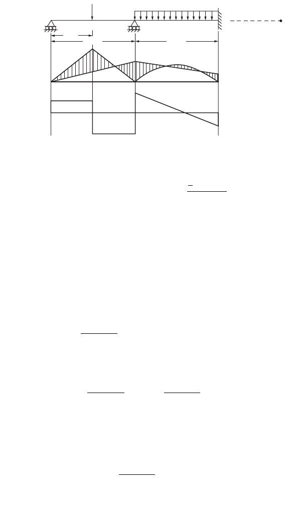
The example in Fig. 47.10 shows the application of this theorem.
For spans AC and BC
Since the support at A is simply supported, M
A
= 0. Therefore,
4M
C
+ M
B
= 1250 (47.11)
Considering an imaginary span BD on the right side of B and applying the theorem for spans CB and BD
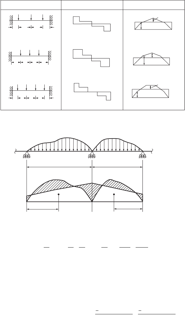
FIGURE 47.8 (continued).
FIGURE 47.9 Continuous beams.
A
L/6
R
A
R
A
=
R
B
=
3P/2
R
B
M
B
M
A
M
B
M
A
M
B
M
A
M
A
=
M
B
=
−19PL/72
M
A
=
M
B
=
−11PL/32
M
A
= M
B
= −5PL/16
M
D
=
M
E
=
5PL/32
M
D
=11PL/72
M
D
= 3PL/16
R
A
R
A
=
R
B
=
3P/2
R
B
R
A
R
A
=
R
B
=
2P
R
B
L/3
L/3
L/6
CDEB
P P P
A
L/4 L/4 L/4 L/4
CDEB
P P P
A
L/8 L/8
L/4
L/4 L/4
CD FEB
PP P P
PL/4
PL/4
3PL/8
LOADING SHEAR FORCE BENDING MOMENT
A
B
C
Load
Bending
moment
L
2
L
1
M
B
M
C
M
A
A
1
A
2
x
1
x
2
M
L
I
M
L
I
L
I
M
L
I
Ax
LI
Ax
LI
AB C
1
1
1
1
2
2
2
2
11
11
22
22
26++
Ê
Ë
Á
ˆ
¯
˜
+= +
Ê
Ë
Á
ˆ
¯
˜
MM M
AC B
¥+ +
()
+¥=
¥¥¥
+
¥¥¥
È
Î
Í
˘
˚
˙
10 2 10 10 10 6
500 10 5
10
250 10 5
10
1
2
1
2
© 2003 by CRC Press LLC
Theory and Analysis of Structures 47-13
(47.12)
Solving Eqs. (47.11) and (47.12) we get
M
B
= 107.2 kNm
M
C
= 285.7 kNm
Shear force at A is
Shear force at C is
Shear force at B is
The bending moment and shear force diagrams are shown in Fig. 47.10.
Beam Deflection
There are several methods for determining beam deflections: (1) moment area method, (2) conjugate
beam method, (3) virtual work, and (4) Castigliano’s second theorem, among others.
The elastic curve of a member is the shape the neutral axis takes when the member deflects under
load. The inverse of the radius of curvature at any point of this curve is obtained as
FIGURE 47.10 Example of a continuous beam.
A
II
C
200 kN
20 kN/m
B
D
5 m
10 m
10 m
500
71.4
117.9
128.6
285.7
250
107.2
82.1
Spans AC and BC
MMM
MM MM
CBD
CB CD
¥+
()
+¥=¥
¥¥
¥
+= -
()
10 2 10 10 6
10 5
10
2
2 500
2
3
Q
S
MM
L
kN
A
AC
=
-
+=-+=100 28 6 100 71 4..
S
MM
L
MM
L
kN
C
CA CB
=
-
+
Ê
Ë
Á
ˆ
¯
˜
+
-
+
Ê
Ë
Á
ˆ
¯
˜
=+
()
++
()
=
100 100
28 6 100 17 9 100 246 5.. .
S
MM
L
kN
B
BC
=
-
+
Ê
Ë
Á
ˆ
¯
˜
=- + =
100
17 9 100 82 1..
© 2003 by CRC Press LLC

47-14 The Civil Engineering Handbook, Second Edition
(47.13)
in which M is the bending moment at the point and EI the flexural rigidity of the beam section. Since
the deflection is small, 1/R is approximately taken as d
2
y/dx
2
, and Eq. (47.13) may be rewritten as:
(47.14)
In Eq. (47.14), y is the deflection of the beam at distance x measured from the origin of coordinate.
The change in slope in a distance dx can be expressed as M dx/EI, and hence the slope in a beam is
obtained as
(47.15)
Equation (47.15) may be stated: the change in slope between the tangents to the elastic curve at two
points is equal to the area of the M/EI diagram between the two points.
Once the change in slope between tangents to the elastic curve is determined, the deflection can be
obtained by integrating further the slope equation. In a distance dx the neutral axis changes in direction
by an amount dq. The deflection of one point on the beam with respect to the tangent at another point
due to this angle change is equal to dd = x dq, where x is the distance from the point at which deflection
is desired to the particular differential distance.
To determine the total deflection from the tangent at one point, A, to the tangent at another point,
B, on the beam, it is necessary to obtain a summation of the products of each dq angle (from A to B)
times the distance to the point where deflection is desired, or
(47.16)
The deflection of a tangent to the elastic curve of a beam with respect to a tangent at another point
is equal to the moment of M/EI diagram between the two points, taken about the point at which deflection
is desired.
Moment Area Method
The moment area method is most conveniently used for determining slopes and deflections for beams
in which the direction of the tangent to the elastic curve at one or more points is known, such as cantilever
beams, where the tangent at the fixed end does not change in slope. The method is applied easily to
beams loaded with concentrated loads, because the moment diagrams consist of straight lines. These
diagrams can be broken down into single triangles and rectangles. Beams supporting uniform loads or
uniformly varying loads may be handled by integration. Properties of some of the shapes of M/EI
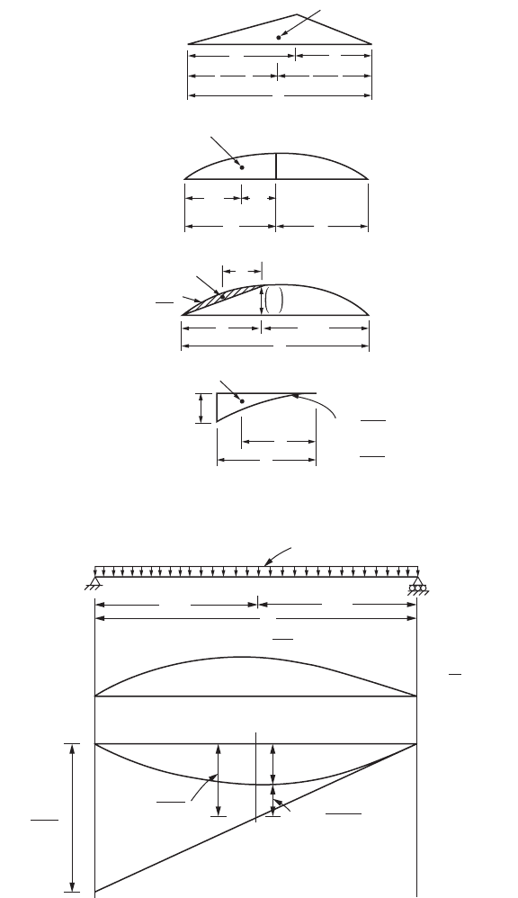
diagrams that designers usually come across are given in Fig. 47.11.
It should be understood that the slopes and deflections obtained using the moment area theorems are
with respect to tangents to the elastic curve at the points being considered. The theorems do not directly
give the slope or deflection at a point in the beam compared to the horizontal axis (except in one or two
special cases); they give the change in slope of the elastic curve from one point to another or the deflection
of the tangent at one point with respect to the tangent at another point. There are some special cases in
which beams are subjected to several concentrated loads or the combined action of concentrated and
uniformly distributed loads. In such cases it is advisable to separate the concentrated loads and uniformly
1
R
M
EI
=
M EI =
dy
dx
2
2
qq
BA
-=
Ú
A
B
M
EI
dx
dd
BA
-=
Ú
A
B
Mx dx
EI
© 2003 by CRC Press LLC
Theory and Analysis of Structures 47-15
distributed loads, and the moment area method can be applied separately to each of these loads. The
final responses are obtained by the principle of superposition.
For example, consider a simply supported beam subjected to uniformly distributed load q, as shown
in Fig. 47.12. The tangent to the elastic curve at each end of the beam is inclined. The deflection, d
1
, of
the tangent at the left end from the tangent at the right end is found as ql
4
/24EI. The distance from the
original chord between the supports and the tangent at the right end, d
2
, can be computed as ql
4
/48EI.
FIGURE 47.11 Typical M/EI diagram.
FIGURE 47.12 Deflection — simply supported beam under UDL.
Center of gravity
Center of gravity
Center of gravity
for half parabola
Center of gravity
w
−
2
(a)( −a)
a
b
+
3
a
+
3
b
(a)
−
2
−
2
a
−
2
A =
w
1
a
2
3
(b)
w = uniform load
a
+ a
(c)
x
y
x =
n
n
+
+
1
2
y = kx
n
A =
n
y
+
1
5
−
8
−
2
3
−
8
−
2
δ
1
=
2
q
4
E
4
I
δ
2
=
4
q
8
E
4
I
δ
c
δ
3
=
1
q
28
E
4
I
q
8
E
2
I
A
B
q/unit length
L/2
EI
L
L/2
E
M
I
diagram
© 2003 by CRC Press LLC
47-16 The Civil Engineering Handbook, Second Edition
The deflection of a tangent at the center from a tangent at the right end, d
3
, is determined as ql
4
/128EI.
The difference between d
2
and d
3
gives the centerline deflection as (5/384) x (ql
4
/EI).
Curved Beams
The beam formulas derived in the previous section are based on the assumption that the member to which
bending moment is applied is initially straight. Many members, however, are curved before a bending
moment is applied to them. Such members are called curved beams. In the following discussion all the
conditions applicable to straight-beam formulas are assumed valid, except that the beam is initially curved.
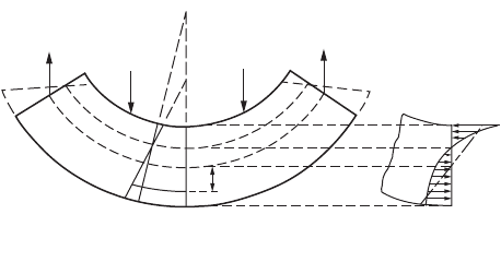
Let the curved beam DOE shown in Fig. 47.13 be subjected to the load Q. The surface in which the
fibers do not change in length is called the neutral surface. The total deformations of the fibers between
two normal sections, such as AB and A
1
B
1
, are assumed to vary proportionally with the distances of the
fibers from the neutral surface. The top fibers are compressed, while those at the bottom are stretched,
i.e., the plane section before bending remains plane after bending.
In Fig. 47.13 the two lines AB and A
1
B
1
are two normal sections of the beam before the loads are
applied. The change in the length of any fiber between these two normal sections after bending is
represented by the distance along the fiber between the lines A
1
B
1
and A¢B¢; the neutral surface is
represented by NN
1
, and the stretch of fiber PP
1
is P
1
P ¢
1
, etc. For convenience, it will be assumed that
line AB is a line of symmetry and does not change direction.
The total deformations of the fibers in the curved beam are proportional to the distances of the fibers
from the neutral surface. However, the strains of the fibers are not proportional to these distances because
the fibers are not of equal length. Within the elastic limit the stress on any fiber in the beam is proportional
to the strain of the fiber, and hence the elastic stresses in the fibers of a curved beam are not proportional
to the distances of the fibers from the neutral surface. The resisting moment in a curved beam, therefore,
is not given by the expression sI/c. Hence the neutral axis in a curved beam does not pass through the
centroid of the section. The distribution of stress over the section and the relative position of the neutral
axis are shown in Fig. 47.13b; if the beam were straight, the stress would be zero at the centroidal axis
and would vary proportionally with the distance from the centroidal axis, as indicated by the dot–dash
line in the figure. The stress on a normal section such as AB is called the circumferential stress.
Sign Conventions
The bending moment M is positive when it decreases the radius of curvature and negative when it
increases the radius of curvature; y is positive when measured toward the convex side of the beam and
negative when measured toward the concave side, that is, toward the center of curvature. With these sign
conventions, s is positive when it is a tensile stress.
Circumferential Stresses
Figure 47.14 shows a free-body diagram of the portion of the body on one side of the section; the
equations of equilibrium are applied to the forces acting on this portion. The equations obtained are
FIGURE 47.13 Bending of curved beams.
D
Q
C
C
′
Q
O′
1
P′
1
Q
B′
B
1
B
P
P
1
O
O
1
N
N
1
A
A
′
A
1
Q
y
E
A
N
O
B
(a) (b)
© 2003 by CRC Press LLC

Theory and Analysis of Structures 47-17
(47.17)
(47.18)
Figure 47.15 represents the part ABB
1
A
1
of Fig. 47.13a enlarged; the angle between the two sections
AB and A
1
B
1
is dq. The bending moment causes the plane A
1
B
1
to rotate through an angle Ddq, thereby
changing the angle this plane makes with the plane BAC from dq to (dq + Ddq); the center of curvature
is changed from C to C¢, and the distance of the centroidal axis from the center of curvature is changed
from R to r. It should be noted that y, R, and r at any section are measured from the centroidal axis and
not from the neutral axis.
It can be shown that the bending stress s is given by the relation
(47.19)
FIGURE 47.14 Free-body diagram of curved beam segment.
FIGURE 47.15 Curvature in a curved beam.
+M
y
YY
X
Z
O
da
y
σ da
σ da
y
BB
1
B′
H
P
1
P
O
A
C′
R
C
R
ρ
ρ
da
y
OO
1
= ds
O
1
O′
1
P′
1
A
1
∆dθ
A
Neutral
surface
dθ + ∆dθ
dθ
SFda
z
==
Ú
00 or s
SMMyda
z
==
Ú
0 or s
s= +
+
Ê
Ë
Á
ˆ
¯
˜
M
aR Z
y
Ry
1
1
© 2003 by CRC Press LLC

47-18 The Civil Engineering Handbook, Second Edition
in which
s is the tensile or compressive (circumferential) stress at a point at distance y from the centroidal axis
of a transverse section at which the bending moment is M; R is the distance from the centroidal axis of
the section to the center of curvature of the central axis of the unstressed beam; a is the area of the cross-
section; and Z is a property of the cross-section, the values of which can be obtained from the expressions
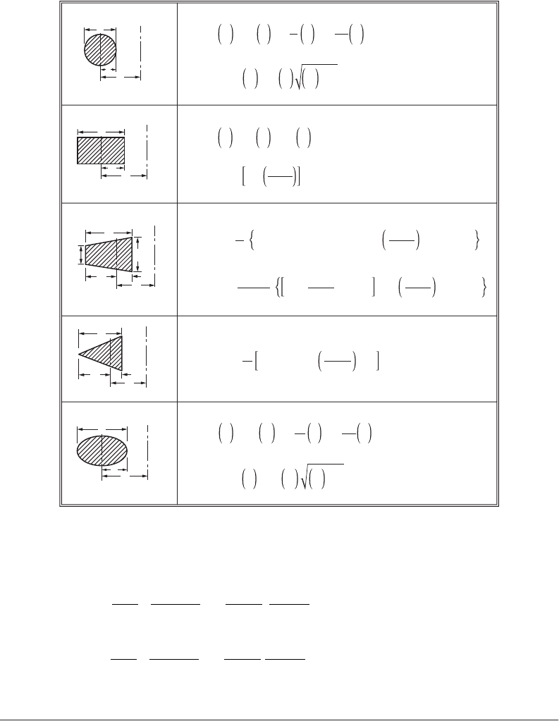
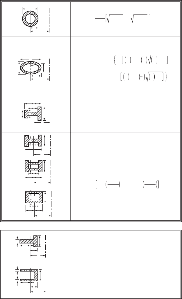
for various areas given in Fig. 47.17. Detailed information can be obtained from Seely and Smith (1952).
Example 47.2
The bent bar shown in Fig. 47.16 is subjected to a load P = 1780 N. Calculate the circumferential stress
at A and B, assuming that the elastic strength of the material is not exceeded.
We know from Eq. (47.19)
in which a = the area of rectangular section (40 ¥ 12 = 480 mm
2
)
R = 40 mm
y
A
= –20
y
B
= +20
P = 1780 N
M = –1780 ¥ 120 = –213,600 N mm.
From Table 47.2.1, for rectangular section
Hence,
FIGURE 47.16 Bent bar.
Z
1
a
y
R+ y
da=-
Ú
s= + +
Ê
Ë
Á
ˆ
¯
˜
P
a
M
aR
1
1
Z
y
R+y
Z1
R
h
log
R+c
Rc
e
=- +
-
È
Î
Í
˘
˚
˙
=
=
hmm
cmm
40
20
Z1
40
40
log
40 20
40 20
0.0986
e
=- +
+
-
È
Î
Í
˘
˚
˙
=
Section A − B
12 mm
40 mm
40 mm
120 mm
A
B
P
P
© 2003 by CRC Press LLC
Theory and Analysis of Structures 47-19
Therefore
= 105.4 N/mm
2
(tensile)
= –45 N/mm
2
(compressive)
47.3 Trusses
A structure that is composed of a number of members pin-connected at their ends to form a stable
framework is called a truss. If all the members lie in a plane, it is a planar truss. It is generally assumed
that loads and reactions are applied to the truss only at the joints. The centroidal axis of each member
is straight, coincides with the line connecting the joint centers at each end of the member, and lies in a
plane that also contains the lines of action of all the loads and reactions. Many truss structures are three-
dimensional in nature. However, in many cases, such as bridge structures and simple roof systems, the
three-dimensional framework can be subdivided into planar components for analysis as planar trusses
FIGURE 47.17 Analytical expressions for Z.
c
h
R
h
R
b
b
1
c
1
c
2
h
c
2
c
1
R
h
c
R
Z = −1 + 2
R
−
c
2
− 2
R
−
c
R
−
c
2
− 1
Z =
1
−
3
c
−
R
2
+
1
−
5
c
−
R
4
+
1
−
7
c
−
R
6
+
...
Z = −1 +
R
−
h
log
e
R
R
+
−
c
c
Z = −1 +
a
R
h
[b
1
h + (R + c
1
)(b − b
1
)] log
e
R
R
+
−
c
c
1
2
− (b − b
1
)h
h
c
R
Z = −1 + 2
h
R
2
(R + c
1
) log
e
R
R
+
−
c
c
1
2
− h
Z = −1 +
(b
2
+
R
b
1
)h
b
1
+
b −
h
b
1
(R + c
1
) log
e
R
R
+
−
c
c
1
2
− (b − b
1
)
Z =
1
−
4
c
−
R
2
+
1
−
8
c
−
R
4
+
6
5
4
c
−
R
6
+
12
7
8
c
−
R
8
+
...
Z =
1
−
4
c
−
R
2
+
1
−
8
c
−
R
4
+
6
5
4
c
−
R
6
+
12
7
8
c
−
R
8
+
...
Z = −1 + 2
R
−
c
2
− 2
R
−
c
R
−
c
2
− 1
s
A
=+
-
¥
+
-
-
Ê
Ë
Á
ˆ
¯
˜
1780
480
213600
480 40
1
1
0.0986
20
40 20
s
B
=+
-
¥
+
+
Ê
Ë
Á
ˆ
¯
˜
1780
480
213600
480 40
1
1
0.0986
20
40 20
© 2003 by CRC Press LLC
47-20 The Civil Engineering Handbook, Second Edition
without seriously compromising the accuracy of the results. Figure 47.18 shows some typical idealized
planar truss structures.
There exists a relation between the number of members, m, the number of joints, j, and the reaction
components, r. The expression is
FIGURE 47.17 (continued).
t/2
t/2
t/2
t/2
h
b
b
b
b
b
b
1
c
2
c
2
c
2
c
2
c
2
c
2
c
2
c
2
c
1
c
1
c
1
c
1
c
1
c
1
c
1
c
1
R
R
c
2
c
1
h
R
R
R
R
b
1
c
4
c
3
t
t
The value of Z for each of these three sections may be
found from the expression above by making
b
1
= b, c
2
= c
1
, and c
3
= c
4
Area = a = 2[(t − b) c
1
+ bc
2
]
Z = − 1 +
R
−
a
[b
1
log
e
(R + c
1
) + (t − b
1
)log
e
(R + c
4
)
+ (b − t)log
e
(R − c
3
) − blog
e
(R − c
2
)]
Z = −1 +
c
2
2
2
−
R
c
2
1
R
2
− c
1
2
− R
2
− c
2
2
Z = − 1 +
bc
2
−
1
b
1
c
1
bc
2
2
c
R
2
2
− 2
c
R
2
c
R
2
2
− 1
− b
1
c
1
2
R
c
1
2
− 2
c
R
1
c
R
1
2
− 1
Z = − 1 +
R
−
a
b log
e
R
R
+
−
c
c
2
2
+ (t − b)log
e
R
R
+
−
c
c
1
1
Z = − 1 +
R
−
a
[t log
e
(R + c
1
) + (b − t) log
e
(R − c
3
) − b log
e
(R − c
2
)]
In the expression for the unequal I given above make
c
4
= c
1
and b
1
= t, then
Area = a = tc
1
− (b − t)c
3
+ bc
2
t
b
c
1
R
t/2
b
t/2
R
c
3
c
2
c
3
c
1
c
2
© 2003 by CRC Press LLC
