Wai-Fah Chen.The Civil Engineering Handbook
Подождите немного. Документ загружается.

Theory and Analysis of Structures 47-121
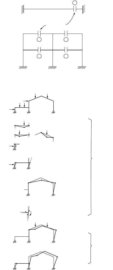
4. Joint: the collapse mode is associated with the rotation of joints of which the adjoining members
developed plastic hinges and deformed under an applied moment, as shown in Fig. 47.100e.
5. Combined: it can be a partial collapse mechanism, as shown in Fig. 47.100f, or it may be a complete
collapse mechanism, as shown in Fig. 47.100g.
FIGURE 47.99 Number of redundants in: (a) a beam, (b) a frame.
FIGURE 47.100 Typical plastic mechanisms.
2
3
3 3
3
R = 2
R = 12
(a)
(b)
Cut section
(a)
Beam mechanisms
Panel mechanism
Gable mechanism
Joint mechanism
Partial collapse
Complete collapse
Combined
mechanisms
Independent
mechanisms
(b)
(c)
(d)
(e)
(f)
(g)
© 2003 by CRC Press LLC
47-122 The Civil Engineering Handbook, Second Edition
The principal rule for combining independent mechanisms is to obtain a lower value of collapse load.
The combinations are selected in such a way that the external work becomes a maximum and the internal
work becomes a minimum. Thus the work equation would require that the mechanism involve as many
applied loads as possible and at the same time eliminate as many plastic hinges as possible. This procedure
is illustrated in the following example.
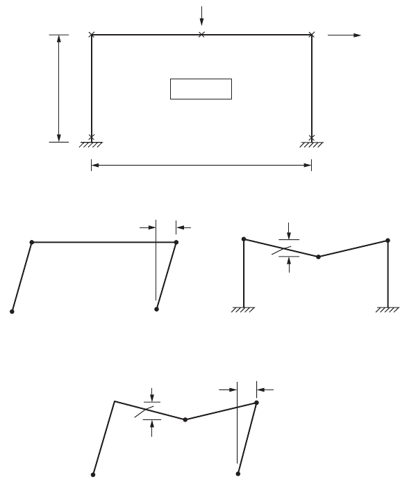
Example 47.13: Rectangular Frame
A fixed-end rectangular frame has a uniform section with M
p
= 20 and carries the load shown in
Fig. 47.101. Determine the value of load ratio l at collapse.
Solution:
Number of possible plastic hinges: N = 5
Number of redundancies: R = 3
Number of independent mechanisms: N – R = 2
The two independent mechanisms are shown in Fig. 47.101b and c, and the corresponding work equations
are
Panel mechanism: 20l = 4(20) = 80 fi l = 4
Beam mechanism: 30l = 4(20) = 80 fi l = 2.67
FIGURE 47.101 Collapse mechanisms of a fixed base portal frame.
10
BC
3λ
2λ
(a)
20
M
p
= 20
E
D
A
A
B
C
(b)
D
θ
θ
θ
θ
θ
10θ
10θ
10θ
10θ
θ
θ
2θ
2θ
2θ
θ
B
A
(c)
C
D
A
B
C
D
(d)
© 2003 by CRC Press LLC

Theory and Analysis of Structures 47-123
The combined mechanisms are now examined to see whether they will produce a lower l value. It is
observed that only one combined mechanism is possible. The mechanism is shown in Fig. 47.101c and
involves cancellation of the plastic hinge at B. The calculation of the limit load is described below:
Panel mechanism: 20l = 4(20)
Beam mechanism: 30l = 4(20)
Addition: 50l = 8(20)
Cancel of plastic hinge: –2(20)
Combined mechanism: 50l = 6(20) fi l = 2.4
The combined mechanism results in a smaller value for l, and no other possible mechanism can produce
a lower load. Thus, l = 2.4 is the collapse load.
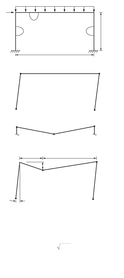
Example 47.14: Frame Subjected to Distributed Load
When a frame is subjected to distributed loads, the maximum moment and hence the plastic hinge
location is not known in advance. The exact location of the plastic hinge may be determined by writing
the work equation in terms of the unknown distance and then maximizing the plastic moment by formal
differentiation.
Consider the frame shown in Fig. 47.102a. The side sway collapse mode in Fig. 47.102b leads to the
following work equation:
which gives
The beam mechanism of Fig. 47.102c gives
which gives
In fact the correct mechanism is shown in Fig. 47.102d, in which the distance Z from the plastic hinge
location is unknown. The work equation is
which gives
To maximize M
p
, the derivative of M
p
is set to zero, i.e.,
42410M
p
=
()
q
M
p
= 60
4
1
2
10 32M
p
qq=
()
M
p
= 40
24 10
1
2
16 20 2 2
20
20
qq q
()
+
()()()
=+
-
Ê
Ë
Á
ˆ
¯
˜
Ê
Ë
Á
ˆ
¯
˜
.zM
z
p
M
zz
z
p
=
+
()
-
()
-
240 16 20
80 2
80 2 80 32 4800 80 16 2 0
2
-
()
-
()
++-
()
()
=zz zz
© 2003 by CRC Press LLC
47-124 The Civil Engineering Handbook, Second Edition
which gives
and
In practice, uniform load is often approximated by applying several equivalent point loads to the member
under consideration. Plastic hinges thus can be assumed to form only at the concentrated load points,
and the calculations become simpler when the structural system is getting more complex.
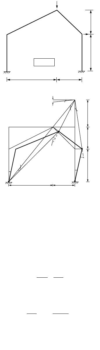
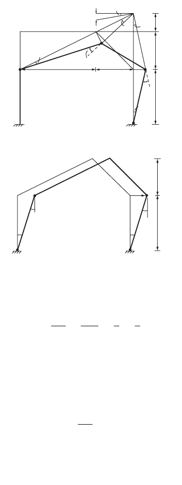
Example 47.15: Gable Frame
The mechanism method is used to determine the plastic limit load of the gable frame shown in Fig. 47.103.
The frame is composed of members with a plastic moment capacity of 270 kip-in. The column bases are
fixed. The frame is loaded by a horizontal load H and vertical concentrated load V. A graph from which
V and H cause the collapse of the frame is to be produced.
FIGURE 47.102 Portal frame subjected to a combined uniform distributed load and horizontal load.
M
p
M
p
M
p
24
B
A
20
(a)
1.6
CD
10
E
BD
(b)
AE
θ
θ
2θ
Zθ
θ
θ
10θ
20θ/(20 − Z)
20θ/(20 − Z)
20 − Z
θ
θ
θ
θ
B
C
(c)
D
Z
(d)
z =- =40 1100 6 83.
M
p
= 69 34.
© 2003 by CRC Press LLC
Theory and Analysis of Structures 47-125
Solution:
Consider the three modes of collapse as follows:
Mechanism 1: plastic hinges form at A, C, D, and E:
The mechanism is shown in Fig. 47.103b. The instantaneous center O for member CD is located at the
intersection of AC and
E
D extended. From similar triangles ACC1 and OCC2, we have
which gives
From triangles ACC¢ and CC¢O, we have
FIGURE 47.103 Collapse mechanisms of a fixed base gable frame.
A
V
C
B
M = 270
18
(a)
9
E
D
H
9
13.5
A
B
C
1
C
2
C
0
C′
D
D′
(f + θ)
(ψ + θ)
9θ
f
ψ
f
θ
θ
θ
11.25
9
13.5
9
18
E
(b)
OC
CC
CA
CC
2
2
1
1
=
OC
CA
CC
CC ft
2
1
1
2
22 5 9
18
11 25==
()
=
.
.
AC OCfq
()
=
()
© 2003 by CRC Press LLC
47-126 The Civil Engineering Handbook, Second Edition
which gives
Similarly, from triangles ODD¢ and EDD¢, the rotation at E is given as
which gives
From the hinge rotations and displacements, the work equation for this mechanism can be written as
Substituting values for y and f and simplifying, we have
V + 2.25H = 180
Mechanism 2: mechanism with hinges at B, C, D, and E:
Figure 47.103c shows the mechanism in which the plastic hinge rotations and displacements at the load
points can be expressed in terms of the rotation of member CD about the instantaneous center O.
FIGURE 47.103 (continued).
0
θ
θ
θ
f
(f + θ)
(θ + ψ)
ψ
9θ
C
1
B
A
18
(c)
C
9
9
D
D′
C′
C
2
4.5
13.5
E
(d)
A
B
θ
θ
θ
θ
13.5
9
D
E
C
13.5θ
fq qqq== ==
OC
AC
CC
CC
2
1
9
8
1
2
DE ODY
()
=
()
q
Y= =
OD
DE
qq15.
VH M
p
9135qffqq
()
+
()
=++
()
++
()
+
[]
. YYY
© 2003 by CRC Press LLC

Theory and Analysis of Structures 47-127
From similar triangles BCC
1
and OCC
2
, we have
which gives
From triangles BCC¢ and CC¢O, we have
which gives
Similarly, from triangles ODD¢ and EDD¢, the rotation at E is given as
which gives
The work equation for this mechanism can be written as
Substituting values of y and f and simplifying, we have
V + 1.5H = 150
Mechanism 3: mechanism with hinges at A, B, D, and E:
The hinge rotations and displacements corresponding to this mechanism are shown in Fig. 47.103d. The
rotation of all hinges is q. The horizontal load moves by 13.5q, but the horizontal load has no vertical
displacement. The work equation becomes
or
H = 80
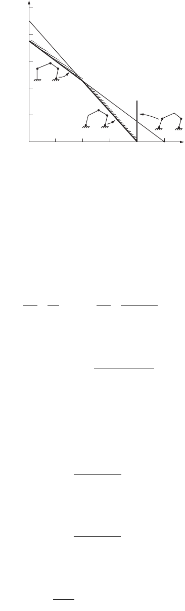
The interaction equations corresponding to the three mechanisms are plotted in Fig. 47.104. By carrying
out moment checks, it can be shown that mechanism 1 is valid for portion AB of the curve, mechanism
2 is valid for portion BC, and mechanism 3 is valid only when V = 0.
OC
CC
BC
CC
2
2
1
1
=
OC
BC
CC
CC
2
1
1
2
9
18
945==
()
= .
BC OCfq
()
=
()
fq qqq== ==
OC
BC
OC
BC
2
1
45
9
1
2
.
DE ODY
()
=
()
q
Y= =
OD
DE
qq
VH M
p
9135qffqq
()
+
()
=++
()
++
()
+
[]
. YYY
HM
p
13 5. q qqqq
()
= +++
()
© 2003 by CRC Press LLC
47-128 The Civil Engineering Handbook, Second Edition
Analysis Aids for Gable Frames
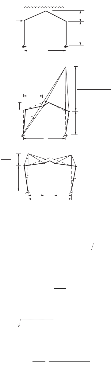
Pin-Based Gable Frames
Figure 47.105a shows a pinned-end gable frame subjected to a uniform gravity load lwL and a horizontal
load l1H at the column top. The collapse mechanism is shown in Fig. 47.105b. The work equation is
used to determine the plastic limit load. First, the instantaneous center of rotation O is determined by
considering similar triangles,
(47.227)
and
(47.228)
From the horizontal displacement of D,
(47.229)
of which
(47.230)
where k = h
2
/h
1
. From the vertical displacement at C,
(47.231)
The work equation for the assumed mechanism is
(47.232)
FIGURE 47.104 Vertical load and horizontal force interaction curve for collapse analysis of gable frame.
200
160
120
80
V
40
C
(2)
B
V + 1.5H = 150
V + 2.25H = 180
(1)
A
(3)
H = 80
100
H
20 40 60 80
OE
CF
L
xL
and
OE
CF
OE
hxh
==
+
12
2
OD OE h
xh xh
x
=-=
-
()
+
1
12
12
qfhOD
1
=
fq=
-
()
+
x
xxk12
bq=
-
-
()
+
1
12
x
xxk
lb
l
fbfq
11
2
2
12Hh
wL
xM
p
+-
()
=++
()
© 2003 by CRC Press LLC
Theory and Analysis of Structures 47-129
which gives
(47.233)
Differentiating M
p
in Eq. (47.233) with respect to x and solving for x,
(47.234)
where
(47.235)
Substituting for x in the expression for M
p
gives
(47.236)
FIGURE 47.105 Pinned base gable frame subjected to a combined uniform distributed load and horizontal load.
(a)
A
B
C
D
E
L
h
1
h
2
= kh
1
λ
1
H
λwL
1 − x
L
h
2
h
1
xL xL
A
B
L
C
F
(c)
E
θ
θ
f
f
D
0
0
xL
2xh
2
h
1
θ
f
β
B
A
F
C
L
(b)
E
D
(1 − x)h
1
+ 2xh
2
x
M
xHh xxwL
kx
p
=
-
()
+-
()
+
()
112
21
11
2
ll
x
A
k
=
-1
AkUkand U
Hh
wL
=+
()
-
()
=11
2
11
2
l
l
M
wL
UU
AAUk
p
=
+
()
+- +
È
Î
Í
˘
˚
˙
l
2
22
8
2
21
© 2003 by CRC Press LLC
47-130 The Civil Engineering Handbook, Second Edition
In the absence of horizontal loading, the gable mechanism, as shown in Fig. 47.105c, is the failure mode.
In this case, letting H = 0 and U = 0 gives (Horne, 1964):
(47.237)
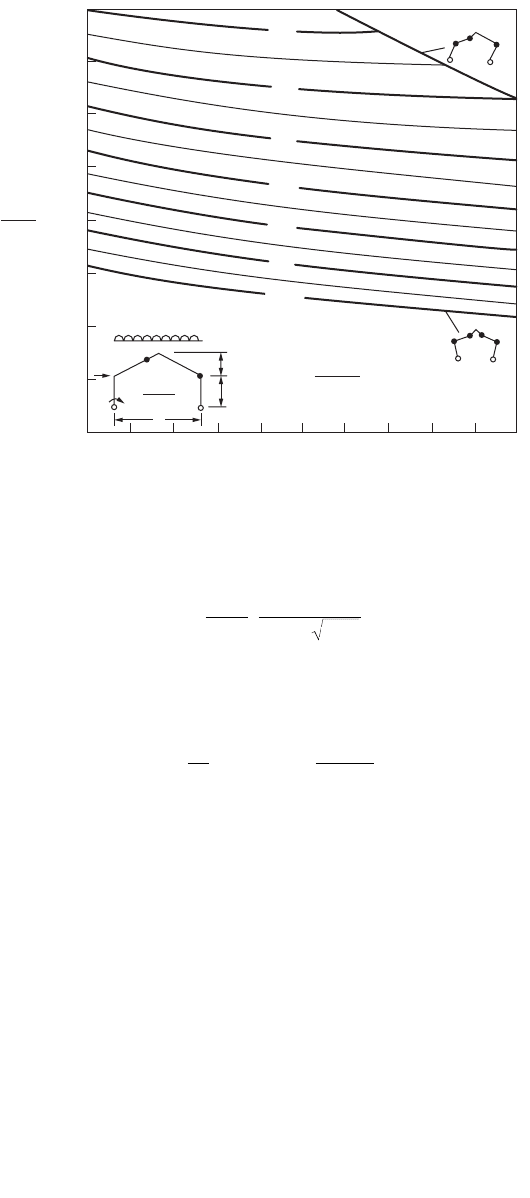
Equation (47.236) can be used to produce a chart, as shown in Fig. 47.106, by which the value of M
p
can be determined rapidly by knowing the values of
(47.238)
Fixed-Base Gable Frames
A similar chart can be generated for fixed-base gable frames, as shown in Fig. 47.107. Thus, if the values
of loading, lw and l
1
H, and frame geometry, h
1
, h
2
, and L, are known, the parameters k and U can be
evaluated and the corresponding value of M
p
/(lwL
2
) can be read directly from the appropriate chart.
The required value of M
p
is obtained by multiplying the value of M
p
/(lwL
2
) by lwL
2
.
Grillages
Grillage is a type of structure that consists of straight beams lying on the same plane, subjected to loads
acting perpendicular to the plane. An example of such a structure is shown in Fig. 47.108. The grillage
consists of two equal simply supported beams of span length 2L and full plastic moment M
p
. The two
beams are connected rigidly at their centers, where a concentrated load W is carried.
The collapse mechanism consists of four plastic hinges formed at the beams adjacent to the point load,
as shown in Fig. 47.108. The work equation is
FIGURE 47.106 Analysis chart for pinned base gable frame.
0.6
Sway mechanism
0.16
0.14
0.12
0.10
0.08
0.06
0.04
0.02
0
U
.
2
λωL
2
M
p
λωL
2
U =
2λ
1
Hh
1
λωL
2
λωL
L
λ
1
H
h
1
kh
1
k = 0.1 0.2 0.3 0.4 0.5 0.6 0.7 0.8 0.9 1.0
Gable mechanism
0.5
0.4
0.3
0.2
0.1
U=0
M
wL
kk
p
=
++ +
È
Î
Í
˘
˚
˙
l
2
8
1
11
k
h
h
and U
Hh
wL
==
2
1
11
2
2
l
l
WL M
p
qq= 4
© 2003 by CRC Press LLC