Wai-Fah Chen.The Civil Engineering Handbook
Подождите немного. Документ загружается.

49-34 The Civil Engineering Handbook, Second Edition
Torsional Flexural Buckling
Theoretical Basis
Apart from local buckling, perhaps the major difference in
behavior between hot-rolled steel and cold-formed steel struc-
tural members is to be found in the relative susceptibility of
the latter to torsional flexural buckling. Designers in hot-rolled
steel do not come across this phenomenon to a great extent,
partly because hot-rolled steel sections are generally thicker
and more compact than cold-formed steel sections, but more
generally because of the greater variety of sectional shapes that
are designed in cold-formed steel. When dealing with mem-
bers that are of arbitrary cross-section, a more general theo-
retical approach must be adopted than that used in the earlier
sections of this chapter.
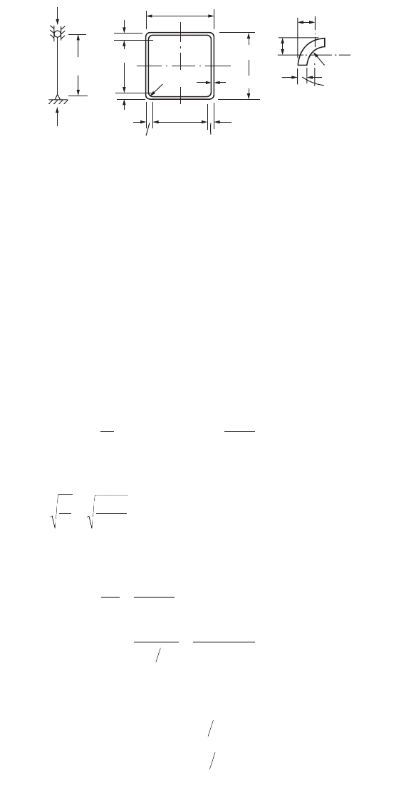
Consider a member having a generally unsymmetrical cross
section, as depicted in Fig. 49.33. If this member is loaded in
compression, it is not possible to determine by inspection the direction in which the cross-section will
move during buckling. For such a cross section, on the basis of classical theory, which is detailed in
Murray (1984) and Allen and Bulson (1980), the deflections of the member will have components in the
x and y directions and twisting will also occur about the shear center, or center of twist. Indeed, if precise
analysis of the situation were to be carried out, it would be found that distortion, or change in shape of
the cross-section, is also a distinct possibility in thin-walled sections, but this complicates the analysis
considerably.
The application of classical theory to deal with cold-formed steel sections has been researched exten-
sively at Cornell University in the U.S. (Chajes and Winter, 1965; Peköz and Celebi, 1969), and Yu (1991)
gives a thorough summary of the design approach based on this work. If we consider that the section of
Fig. 49.33 is loaded through its centroid, and axes x-x and y-y are the principal axes, then the buckling
load, which in the general case is due to a combination of biaxial flexure and twisting, and thus denoted
P
TF
, may be obtained from the following equation:
(49.36)
In this equation I
c
is the polar second moment of area with respect to the shear center of the section;
P
EX
and P
EY
are the critical loads for buckling about the x and y axes, respectively; and P
T
is the torsional
buckling load. The dimensions x
o
and y
o
are the distances between the centroid of the section and its
shear center measured in the x and y directions, respectively. The smallest root of the equation gives the
value of P
TF
of interest, and this is always less than or equal to the smallest value of the individual critical
loads.
If the member has simple support conditions, as normally defined, at its ends, then P
EX
and P
EY
are
simply the Euler loads for buckling about the x-x and y-y axes, respectively. The torsional buckling load,
P
T
, however, is not fully described by the commonly accepted simple support conditions; closer exami-
nation of the support conditions must be carried out to define this load.
P
T
is defined by the following equation:
(49.37)
where G = the shear modulus for the material
J = the torsion constant for the section
FIGURE 49.33 Generally unsymmetrical
cross-section.
y
o
x
o
S.C.
X
C.G.
X
Y
Y
I
A
PPPPPPPyPP xPP
C
TF EY TF EX TF T TF o TF EX o TF EY
-
()
-
()
-
()
--
()
+-
()
{}
=
22 2
0
P
r
GJ k E
C
L
T
o
w
E
=+
Ê
Ë
Á
ˆ
¯
˜
1
2
2
2
p
© 2003 by CRC Press LLC
Cold Formed Steel Structures 49-35
C
w
= the warping constant for the section
r
o
= the polar radius of gyration about the shear center, given by
(49.38)
where r
x
and r
y
are radii of gyration corresponding to the x and y axes, respectively.
The constant k is dependent on the degree of warping restraint afforded by the end connections of
the column. If warping is completely unrestrained, then k = 1. There is, as can be seen, an analogy with
the Euler load for flexural buckling, in which a fully fixed column has a buckling load four times as great
as the corresponding simply supported column.
Warping Restraint
We can see that a column that is nominally simply supported, or simply supported with regard to flexural
buckling, may exhibit a wide range of variation in buckling load under the more general torsional flexural
buckling situation. If the walls of such a column are very thin, then for column lengths of commercial
applicability the torsion constant, J, which is equal to Sbt
3
/3, can become very small in comparison with
C
w
/L
E
2
, and the degree of warping restraint becomes very important.
The degree of warping restraint by different types of end connections is not easy to quantify, as it
depends on a wide range of factors. However, warping of the ends is often prevented by the end plates,
and the effects of torsional flexural buckling are often minimized. This assumption of full warping
restraint is therefore optimistic for the general case.
In the AISI specification, and in the various design codes based on the AISI specification, the opposite
view is taken. Here it is assumed that for safe design no account should be taken of the effects of
connections on warping restraint, and so torsional flexural buckling is based on k = 1. This gives much
lower design loads for many cases and results in torsional flexural buckling being the governing design
criterion for a much wider range of section shapes than is the case. Eurocode 3, Part 1.3, considers a
column to have an effective length with regard to torsional flexural buckling, and this effective length
may be different from that for flexural buckling and depends on the degree of torsion and warping
restraint at the column ends. This code gives some indicative drawings of the connections for which
restraint may be considered sufficient to take the restraints applied into account in estimating the effective
length.
Members under Combined Bending and Compression
Under practical conditions structural members are very often subjected to combinations of bending and
axial loading. The interaction of the different effects must be taken into account when this occurs. When
the axial loading is compressive there are possibilities that the different types of buckling that can occur
for both beams and columns may interact with each other, and this must be guarded against. Even in
the case of members subjected to combinations of bending and tension there are possibilities that buckling
of some form may occur, and this must be taken into consideration. In this section, however, we shall
consider combinations of compressive forces and bending.
Under hypothetical simplified conditions in which buckling effects are absent and a member behaves
perfectly elastically until failure occurs when the maximum stress reaches yield, the effects of each different
type of loading that acts on a member can simply be added together to produce an equation governing
the capacity under simultaneous applications of moment, M, and axial load, P:
(49.39)
where P
s
= the load capacity in the absence of moments
M
y
= the moment capacity in the absence of axial loads
r rrxy
oxyoo
=+++
()
2 222
12
P
P
M
M
sy
+=1
© 2003 by CRC Press LLC
49-36 The Civil Engineering Handbook, Second Edition
If buckling possibilities are negligible and if the material has any postyield capacity, this type of equation
tends to give conservative results of the load-carrying capacity of the member under combined loadings.
If, on the other hand, there is any tendency for the member to undergo buckling, then this type of
equation can underestimate the degree of interaction and give nonconservative estimates of carrying
capacity.
The AISI recommends that the axial force and bending moments satisfy the following interaction
equations:
(49.40)
(49.41)
When P/P
a
£ 0.15, the following formula may be used in lieu of the above two formulas:
(49.42)
where P = the applied axial load
M
x
and M
y
= the applied moments with respect to the centroidal axes of the effective section
determined for the axial load alone
P
a
= the allowable axial load determined in accordance with Section C4
P
a0
= the allowable axial load determined in accordance with Section C4, with F
n
=
F
y
M
ax
and M
ay
= the allowable moments about the centroidal axes determined in accordance with
Section C3
C
mx
and C
my
= the coefficients, whose values shall be taken from the AISI specifications
1/a
x
and 1/a
y
= the magnification factors, 1/[1 – (O
c
P/P
cr
)], in which O
c
is the factor of safety used
in determining P
a
and
P
cr
=46
For the above equation, I
b
is the moment of inertia of the full, unreduced cross-section about the axis
of bending; L
b
is the actual unbraced length in the plane of bending; and K
b
is the effective length factor
in the plane of bending.
BS 5950 considers two different possibilities that should be examined in dealing with the interaction
of axial compression and bending:
1. The capacity of the member may be exceeded locally
at discrete points at which the maximum loadings
occur.
2. The overall capacity of the member to resist buckling
due to the action of the combined loadings may be
exceeded.
The first possibility is likely to occur in members subjected
largely to bending with some additional axial loading. At
points of maximum moment, as indicated in Fig. 49.34, the
effects of the axial loading on the ultimate condition must be considered. This situation can be adequately
covered by a linear interaction equation, and in BS 5950, Part 5, the following expression is used to check
P
P
CM
M
CM
M
a
mx x
ax x
my y
ay y
++£
aa
10.
P
P
M
M
M
M
a
x
ax
y
ay0
10++£.
P
P
M
M
M
M
a
x
ax
y
ay
++£10.
p
2
EI
b
K
b
L
b
()
2
------------------
FIGURE 49.34 Moment variation along a
member with axial and transverse loading.
F
B
A
P
M
C
P
Point of
maximum
moment
© 2003 by CRC Press LLC
Cold Formed Steel Structures 49-37
the local capacity of a member subjected to axial load F
c
and bending moments M
x
and M
y
about the x
and y axes, respectively:
(49.43)
where P
cs
is the axial load capacity in the absence of moments and M
cx
and M
cy
are the moment capacities
if the member is subjected only to bending about the relevant axis in the absence of all other load actions.
This equation should be satisfied at discrete points on the member where the local load or moment
magnitudes are at their peak. It is worthy of mention here that this equation takes account of local
buckling effects, since the calculated load and moment capacities are determined on the basis of the
methods already described in this book.
The second possibility that must be considered is that the overall buckling capacity of the member
may be attained by a combination of loads. The types of buckling, in addition to local buckling, that are
possible are flexural buckling or torsional flexural buckling of members loaded largely in compression
and lateral torsional buckling of members loaded largely in bending. A suitable overall buckling capacity
check should consider all of these possibilities. BS 5950, Part 5, prescribes two interaction equations to
deal with the overall buckling capacity check; the particular equation to be used in any given situation
is dependent upon whether or not lateral torsional buckling is a possibility. Eurocode 3, Part 1.3, uses a
single interaction equation for combined bending and compression (although a modified equation must
also be satisfied for members susceptible to lateral torsional buckling), and this equation is substantially
different from those of the AISI code or the U.K. code. Comparisons of all three codes with experimental
results have not been conclusive to date and suggest that despite the differences in setup the various
methods are reasonably accurate and safe.
Members under Combined Bending and Tension
In the case of members subjected to combinations of bending and tension there is not, in general, any
need for an overall buckling capacity check, as the application of tensile loads has no tendency to increase
the possibility of overall buckling. There are, of course, possibilities that the effects of local buckling may
be present in the member, since not all elements of a cross-section will be in tension under the combi-
nation of loads.
In BS 5950, Part 5, an interaction equation of the same form as Eq. (49.39) is used to check the local
capacity at discrete points on a member. The relevant equation is
(49.44)
with
In this equation F
t
and P
t
are the applied tensile load and the tensile capacity of the member, respectively;
M
cx
and M
cy
are the moment capacities computed in the absence of any other loading. Since M
cx
, for
example, is evaluated on the basis of an effective cross-section, local buckling is automatically taken into
account in the interaction equation.
Example 49.4
Compute the allowable axial load for the square tubular column shown in Fig. 49.35. Assume that the
yield point of steel is 40 ksi and K
x
L
x
= K
y
L
y
= 10 ft.
F
P
M
M
M
M
c
cs
x
cx
y
cy
++£1
F
P
M
M
M
M
t
t
x
cx
y
cy
++£1
M
M
M
M
x
cx
y
cy
££11
© 2003 by CRC Press LLC
49-38 The Civil Engineering Handbook, Second Edition
Solution:
The solution given below is based on the AISI code.
Since the square tube is a doubly symmetric closed section, it will not be subject to torsional flexural
buckling.
Sectional Properties of Full Section
Nominal Buckling Stress, F
n
— The elastic flexural buckling stress, F
e
, is computed as follows:
Since F
e
> F
y
/2 = 20 ksi,
Effective Area, A
eff
— Because the given square tube is composed of four stiffened elements, the effective
width of stiffened elements subjected to uniform compression can be computed by using k = 4.0:
FIGURE 49.35 Example 49.4.
R = 3/16"
P
I
x
= I
y
= 0.00024 in.
R = 3/16"
t = 0.105"
t = 0.105"
x
x
y
x
−
y
−
y
x
x
y
y
10.00"
10.00"
0.2925"
0.2925"
0.2925"
0.2925"
w = 9.415"
w = 9.415"
10"
P
x
−
=
y
−
= 0.1373 in.
A = 0.0396 in.
2
(Negligible)
bRt in
Ain
II
xy
=-+
()
=- +
()
=
=¥+
()
=
==
()()
+-
Ê
Ë
Á
ˆ
¯
˜
È
Î
Í
Í
˘
˚
˙
˙
+
()
-
10 00 2 10 00 2 0 1875 0 105 9 415
49415 0 105 0 0396 4 113
20105
1
12
9 415 9 415 5
0 105
2
400396 5 0 0 1373
2
3
2
......
... ..
...
.
...
(()
=
== = =
2
4
66 75
66 75
4 113
4 029
..
.
.
..
in
rr
I
A
in
xy
x
KL
r
OK
F
E
KL r
ksi
e
=
¥
=<
=
()
=
()
()
=
10 12
4 029
29 78 200
29 500
29 78
328 3
2
2
2
2
.
. ..
,
.
.
p
p
FF FF
ksi
ny y e
=-
()
=- ¥
()
[]
=
14
40 1 40 4 328 3
38 78
.
.
© 2003 by CRC Press LLC
Cold Formed Steel Structures 49-39
Since ,
The effective area is (4.73 ¥ 0.105 + 0.0396) = 2.145 in.
2
Nominal and Allowable Loads:
The use of W
c
= 1.92 is because the section is not fully effective.
49.5 Connections for Cold-Formed Steelwork
All of the connection methods applicable to hot-rolled sections, such as bolting and welding, are also
applicable to cold-formed steel sections at the thicker end of the range. In the case of thinner cold-formed
steel sections an extremely wide assortment of proprietary fasteners and fastening techniques exists. This
wide range raises problems in setting realistic and reliable approaches to defining connection strength,
and evaluation of the connection properties on the basis of testing is generally undertaken.
Types of Fastener
Davies (Rhodes, 1991) listed fasteners in three main groupings, as shown in Table 49.2
The selection of the most suitable type of fastener for a given application is governed by several factors,
notably:
1. load-bearing requirements viz. strength, stiffness, and deformation capacity
2. economic requirements viz. number of fasteners required, cost of labor and materials, skill required
in fabrication, design life, maintenance, and ability to be dismantled
TA BLE 49.2 Typical Applications of Different Types of Fastener
Thin to Thin
Thin to Thick or
Thin to Hot Rolled
Thick to Thick or
Thick to Hot Rolled
Self-drilling self-tapping screws
Blind rivets
Single-flare V welds
Spot welds
Lock seaming
Self-drilling self-tapping screws
Fired pins
Bolts
Arc puddle welds
Bolts
Arc welds
bt
p
E
bt
ksi
f
p
cr
cr
==
=
-
()
()
=
==
9 415 0 105 89 67
4
12 1
1
13 26
40
13 26
1 737
2
2
2
.. .
.
.
.
max
p
n
f
p
cr
max
.> 0 63755
bb
p
f
p
f
in
eff
cr cr
=-
È
Î
Í
Í
˘
˚
˙
˙
=
max max
.
..
1022
473
PAF kips
PP kips
nen
anc
==
()()
=
== =
2 145 38 78 83 18
83 18 1 92 43 32
.. .
.. .W
© 2003 by CRC Press LLC
49-40 The Civil Engineering Handbook, Second Edition
3. durability viz. resistance to aggressive environments
4. watertightness
5. appearance
Although structural engineers tend to be primarily concerned with the most economical way of meeting
the load-bearing requirements, in many applications other factors may be equally important.
Bolts
The use of bolts to connect cold-formed steel components follows a practice similar to that of hot-rolled
construction; however, because of the thinness of the material and the relatively small size of the com-
ponents, the main design considerations tend to be end distance and bearing. With regard to bearing it
is worth noting that hot-rolled steel design codes tend to have significantly different design treatments
of this than cold-formed steel codes. This may be partially due to the different behavior of thin material,
but is mainly due to the adoption of different philosophies by the writers of cold-formed steel and hot-
rolled steel codes. In British codes in particular, the cold-formed steel rules are based on strength design,
while the hot-rolled steel rules are based on limiting slip. Table 49.3, from Davies (Rhodes, 1991), shows
the comparison between permissible bearing stresses in bolted connections according to various codes.
Self-Tapping Screws
Self-tapping screws fall into two distinct types, depending on whether or not they require a predrilled
hole. Conventional self-tapping screws require a predrilled hole and fall into a number of subgroups,
depending on the type of thread, head, and washer. Self-drilling self-tapping screws drill their own hole
and form their own thread in a single operation. There are two basic types, depending on the thickness
of the base material. Both of these screws are usually combined with washers that serve to increase the
load-bearing capacity or sealing ability.
Blind Rivets
Blind rivets are normally used for fastening two thin sheets of material together when access is available
from one side only. These are installed in a single operation, for example, by pulling a mandrel that
forms a head on the blind side of the rivet and expands the rivet shank. Fastening is completed when
the mandrel either pulls through or breaks off. This type of fastener generally requires strength consid-
erably in excess of the sheet material to minimize possibilities of brittle failure.
TABLE 49.3 Permissible Bearing Stress in Bolted Connections
Code Bearing Stress Basis
Addendum 1 (April 1975) to BS 449
BS 5950, Part 1 (hot-rolled)
BS 5950, Part 5 (cold formed)
a
(a) t £ 1 mm
(b) 1 mm £ t £ 3 mm
(c) 3 mm £ t £ 8 mm
AISI specification (August 1986)
(a) with washers
(b) without washers
European recommendations
(a) t £ 1 mm
(b) 3 mm £ t £ 6mm
Eurocode 3, Part 1.3
1.4U
s
0.64(U
s
+ Y
s
)
2.1Y
s
(1.65 + 0.45t)Y
s
3.0Y
s
1.35U
s
to 1.50U
s
1.00U
s
to 1.35U
s
2.1Y
s
4.3Y
s
2.5 U
s
Permissible stress
Limit state
Limit state
Permissible stress
Limit state
Limit state
Note: Y
s
= yield stress of fastened sheet, U
s
= ultimate stress of fastened sheet.
a
Va lues in BS 5950, Part 5, are reduced by 25% unless two washers are used.
© 2003 by CRC Press LLC

Cold Formed Steel Structures 49-41
Fired Pins
These pins, as the name suggests, are fired through thin material into thicker base material to form a
connection. Two different methods of firing the pins are commonly used: powder actuation and pneu-
matic actuation. In the former the pins are fired from a tool that contains an explosive cartridge, and in
the latter compressed air is used as the firing agent. Fired pins generally provide a very tight grip and a
very good sealing capability.
Spot Welds
Electrical resistance spot welds are a widely used method of connecting thin sheets. In the United Kingdom
these are governed by BS 1140, General Requirements for Spot Welding of Light Assemblies in Mild Steel,
and recommendations regarding weld sizes and capacities are provided in BS 5950, Part 5, and the AISI
specification. Further information on loads in resistance spot welds has been given by Baehre and
Berggren (1973).
Arc Welds
Conventional fillet and butt welds are applicable to cold-formed steel sections if the material is relatively
thick, and in such cases design considerations are the same as those for hot-rolled sections. In the case
of thinner material a wide range of special weld types are used in, but not outside of, the U.S. . Guidance
on making these special welds has been given by Blodgett (1978). Expressions for the evaluation of the
ultimate loads for various types of these connections are available from a large testing and analysis
program carried out by Peköz and McGuire (1979).
Clinch Joints and Rosette Joints
A relatively new method of connecting components together is mechanical clinching. This technique was
originally developed for use in the automobile industry, but in recent years has found a number of
applications in cold-formed steel construction and has been the subject of substantial research (e.g.,
Davies et al., 1996). In making clinched joints, hydraulic tools are used as a punch-and-die set that shears
and deforms the material to be connected to produce a connection in which material from one sheet
bears on material from another, and the connection is dependent only on the parent material.
Another type of connection that is uniquely suited to light-gauge material and requires no additional
fixings is the Rosette joint. In this joint holes are punched into the two adjoining strips of material at
the connection point, with one of the sheets having a reduced diameter to form a collar. In the joining
process the collar is snapped into the hole in the adjoining strip, and the Rosette tool penetrates the hole
and collar, expands, and is pulled back to crimp the collar to the opposite side of the hole, thus producing
a secure connection. Details of Rosette joints may be found, for example, in Makelainen et al. (1999).
Assemblies of Fasteners
The available information on the the behavior of assemblies of fasteners in light-gauge steelwork suggests
that the performance of such assemblies is not in any way inferior to that of similar connection assemblies
in hot-rolled members. Connections in cold-formed members, however, do tend to be more flexible and
ductile than in hot-rolled members, and herein lies a bonus that is well appreciated in some areas of
cold-formed steel usage. The ductility afforded by such connections can provide the “plastic plateau”
behavior that often occurs in hot-rolled sections, thus allowing redistribution of moments in the postyield
range. A prime example of this in the United Kingdom is the wide use of “sleeves” in purlin design. These
sleeves are used to connect purlins in a semirigid fashion, which produces a moment distribution close
to the ideal at the point of failure.
49.6 Sheeting and Decking
There has been in the recent past a substantial increase in the usage of profiled sheeting and decking,
and this has been accompanied by a corresponding development of the design principles applicable to
© 2003 by CRC Press LLC
49-42 The Civil Engineering Handbook, Second Edition
this type of construction. Although only a few years ago 3-in. corrugated profiles or simple trapezoidal
profiles were the norm, today there is a multiplicity of different shapes available. Profiles can be obtained
in a wide variety of colors, surface coatings, etc., with a life to first maintenance of up to 25 years. There
have been a large number of developments of structural improvements, involving the use of thinner
material, of increased yield strength in highly stiffened profiles. It is most probable, however, that in this
area improvements in aesthetics, utility, and durability outweigh the structural improvements.
Profiles for Roof Sheeting
Cold roof construction is the term applied to construction in which profiled steel sheeting is used as the
outer waterproof skin of a roof, with insulation placed inside this skin. It is important that the skin
should provide the optimum resistance to moisture penetration, and the side laps should occur near the
crests of the corrugations. With modern fasteners, e.g., self-drilling self-tapping screws with neoprene
washers, it is quite permissible to fix the sheeting to the roof purlins through the troughs. These fasteners
satisfactorily prevent moisture penetration, while providing various structural benefits in the fixity
provided to the purlins over through-crest fixings.
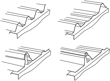
Modern profiles can be grouped into four main types, as illustrated in Fig. 49.36. For the trapezoidal
profile shown in Fig. 49.36a, it is found that to obtain the most economic use of material for a given
span and loading, using standard analysis procedures, the thickness of material and web slope angle that
result are impractical, the thickness usually being very small and the web slope very shallow. Fairly wide
variations in the trapezoidal geometry result in relatively small variations in the economy, and the design
of this type of sheeting is generally governed by practical considerations. In the profile of Fig. 49.36b,
again a fairly widely used shape of profile, the trapezoidal shape is altered to incorporate intermediate
stiffeners in the lower flanges. In order to reduce or eliminate the requirement to penetrate the skin with
fasteners, concealed fixed or standing seam sheeting has been developed over a number of years
(Fig. 49.36c and d). The fixing in these systems is generally by means of clips that connect mechanically
to the sheeting and by screws to the purlin, with the mechanical connections to the sheeting often
incorporated in the standing seam, eliminating penetration of the sheeting. In this type of system the
purlin–sheeting connections are less useful in providing stability to the purlin than the more direct screw
fixings, and may necessitate close consideration of purlin design in such circumstances.
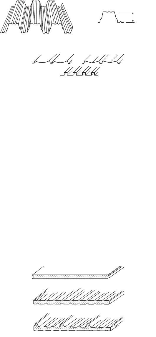
Profiles for Roof Decking
Profiled steel decking, supporting a built-up finish, including insulation and waterproofing, is often
termed warm roof construction. In this type of construction there is a tendency toward longer spans, more
complex profiles, and the use of higher strength steels. A typical profile resulting from these tendencies
is shown in Fig. 49.37. The profile depth is of the order of 4 in., and the material yield strength is of the
FIGURE 49.36 Typical roof sheeting profiles.
(a) (b)
(c) (d)
© 2003 by CRC Press LLC
Cold Formed Steel Structures 49-43
order of 50 ksi. These profiles are suitable for spans up to 30 ft and can thus eliminate the need for
purlins. In general, stiffeners are rolled into both the flanges and the webs, as flanges and webs are slender
and require stiffeners for efficiency.
There are nowadays a large number of different design specifications dealing with roof decking. In
Europe calculation procedures for complex shapes, as shown in Fig. 49.37, have been developed in Sweden
for incorporation into the Swedish code of practice (Höglund, 1980), and these procedures form the
basis of the European recommendations (ECCS, 1983), as well as the national standards of some European
countries, for example, DIN 18807 (1987). These procedures have been verified by a very substantial
number of tests (Baehre and Fick, 1982).
Wall Coverings
Wall cladding carries significant wind loading and must satisfy structural considerations. However, the
aesthetic considerations here are so strong, since the appearance of a building is very substantially
dependent on the sheeting, that aesthetics are often the primary consideration. Typical wall cladding
profiles are shown in Fig. 49.38. By virtue of the variety of profiles available, the wide range of coatings
and colors, and the possibility of orienting the cladding in any desired direction, there is substantial scope
for imagination and artistry in the use of modern wall coverings in building design.
Composite Panels
Composite panels, having outer faces of thin steel (or other material such as aluminum) and an internal
core of foamed plastic (such as polyurethane or expanded polystyrene), are now widely used in construc-
tion (Fig. 49.39). The design criteria for composite panels are complex and are not discussed here.
FIGURE 49.37 Typical long-span decking profiles.
FIGURE 49.38 Typical wall cladding profiles.
FIGURE 49.39 Typical sandwich panels: (a) panel with flat faces, (b) panel with profiled faces, (c) panel with profiled
face.
= 100 mm
(a)
(b)
(c)
© 2003 by CRC Press LLC