Wai-Fah Chen.The Civil Engineering Handbook
Подождите немного. Документ загружается.

50-16 The Civil Engineering Handbook, Second Edition
1. Length of column. The unsupported length, l
u
, is defined in ACI 10.11.1 as the clear distance between
floor slabs, beams, or other members capable of giving lateral support to the column.
2. Effective length. The effective length factors, k, used in calculating d
b
shall be between 0.5 and 1.0
(ACI 10.11.2.1). The effective length factors used to compute d
s
shall be greater than 1 (ACI
10.11.2.2). The effective length factors can be estimated using ACI Fig. R10.11.2 or using ACI
Equations (A)–(E) given in ACI R10.11.2. These two procedures require that the ratio, y, of the
columns and beams be known:
(50.44)
In computing y it is acceptable to take the EI of the column as the uncracked gross E
c
I
g
of the
columns and the EI of the beam as 0.5 E
c
I
g
.
3. Definition of braced and unbraced frames. The ACI Commentary suggests that a frame is braced if
either of the following are satisfied:
(a) If the stability index, Q, for a story is less than 0.04, where
(50.45)
(b) If the sum of the lateral stiffness of the bracing elements in a story exceeds six times the lateral
stiffness of all of the columns in the story.
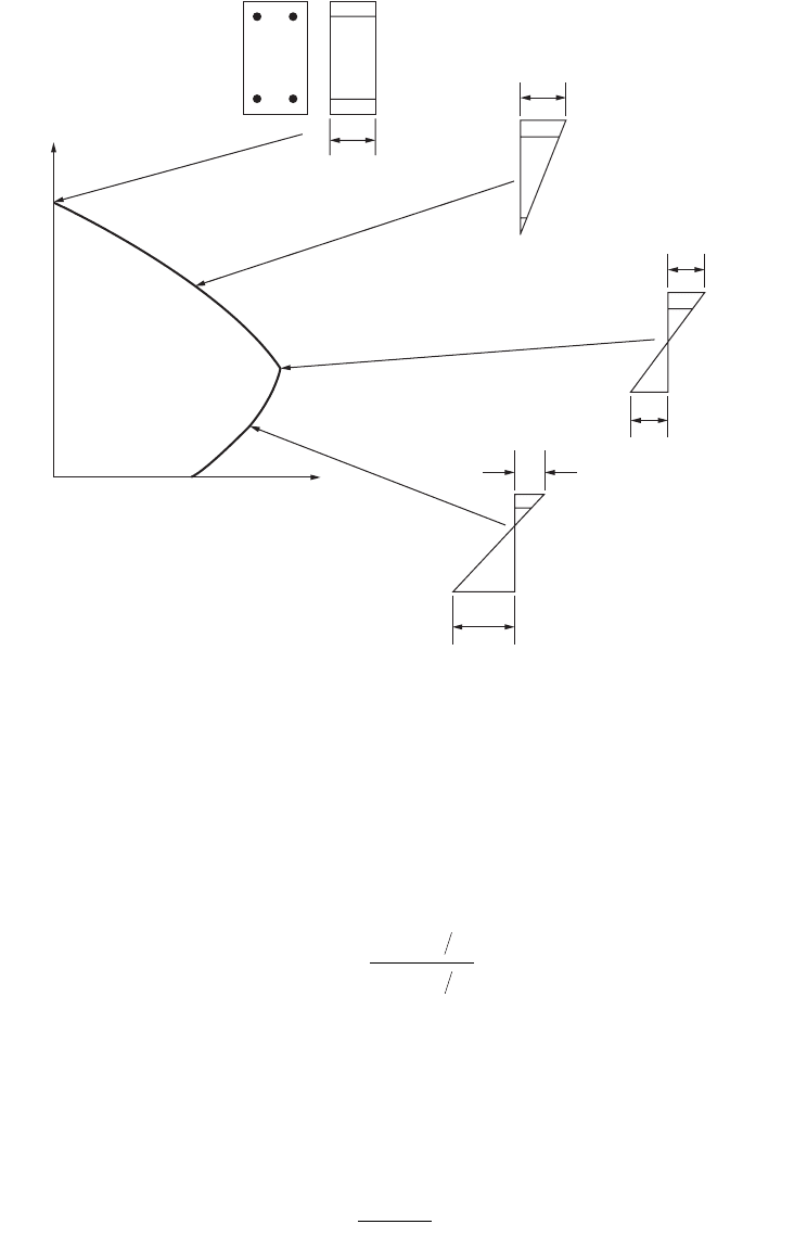
FIGURE 50.3 Strain distributions corresponding to points on interaction diagram.
e
su
> e
y
Pure compression
e
cu
e
cu
e
cu
e
cu
e
y
A
B
C
D
E
Moment,
M
n
Balanced failure
Axial load,
P
n
y=
()
()
Â
Â
EI l
EI l
cc c
bb b
Q
P
Hh
uu
us
=£
Â
D
004.
© 2003 by CRC Press LLC
Structural Concrete Design 50-17
4. Radius of gyration. For a rectangular cross section r equals 0.3 h, and for a circular cross section r
equals 0.25 h. For other sections, r equals .
5. Considerations of slenderness effects. ACI 10.11.4.1 allows slenderness effects to be neglected for
columns in braced frames when
(50.46)
ACI 10.11.4.2 allows slenderness effects to be neglected for columns in unbraced frames when
(50.47)
If kl
u
/r exceeds 100, ACI 10.11.4.3 states that design shall be based on second-order analysis.
6. Minimum moments. For columns in a braced frame, M
2b
shall be not less than the value given in
ACI 10.11.5.4. In an unbraced frame ACI 10.11.5.5 applies for M
2s
.
7. Moment magnifier equation. ACI 10.11.5.1 states that columns shall be designed for the factored
axial load, P
u
, and a magnified factored moment, M
c
, defined by
(50.48)
where M
2b
is the larger factored end moment acting on the column due to loads causing no
appreciable sidesway (lateral deflections less than l/1500) and M
2s
is the larger factored end moment
due to loads that result in an appreciable sidesway. The moments are computed from a conven-
tional first-order elastic frame analysis. For the above equation, the following apply:
(50.49)
For members braced against sidesway, ACI 10.11.5.1 gives d
s
= 1.0.
(50.50)
The ratio M
1b
/M
2b
is taken as positive if the member is bent in single curvature and negative if
the member is bent in double curvature. Equation (50.50) applies only to columns in braced
frames. In all other cases, ACI 10.11.5.3 states that C
m
= 1.0.
(50.51)
where
(50.52)
or, approximately
(50.53)
IA
kl
r
M
M
ub
b
<-34 12
1
2
kl
r
u
< 22
MM M
cbbss
=+dd
22
d
f
d
f
b
m
uc
s
uc
C
PP
PP
=
-
≥
=
-
≥
ÂÂ
1
10
1
1
10
.
.
Cj
M
M
m
b
b
=+ ≥06 04 04
1
2
.. .
P
EI
kl
c
u
=
()
p
2
2
EI
EI EI
cg sse
d
=
+
+
5
1 b
EI
EI
cg
d
=
+
25
1
.
b
© 2003 by CRC Press LLC
50-18 The Civil Engineering Handbook, Second Edition
When computing d
b
,
(50.54)
when computing d
s
,
(50.55)
If d
b
or d
s
is found to be negative, the column should be enlarged. If either d
b
or d
s
exceeds 2.0,
consideration should be given to enlarging the column.
Columns under Axial Load and Biaxial Bending
The nominal ultimate strength of a section under biaxial bending and compression is a function of three
variables, P
n
, M
nx
, and M
ny
, which may also be expressed as P
n
acting at eccentricities e
y
= M
nx
/P
n
and
e
x
= M
ny
/P
n
with respect to the x and y axes. Three types of failure surfaces can be defined. In the first
type, S
1
, the three orthogonal axes are defined by P
n
, e
x
, and e
y
; in the second type, S
2
, the variables
defining the axes are 1/P
n
, e
x
, and e
y
; and in the third type, S
3
, the axes are P
n
, M
nx
, and M
ny
. In the
presentation that follows, the Bresler reciprocal load method makes use of the reciprocal failure surface
S
2
, and the Bresler load contour method and the PCA load contour method both use the failure surface S
3
.
Bresler Reciprocal Load Method
Using a failure surface of type S
2
, Bresler proposed the following equation as a means of approximating
a point of the failure surface corresponding to prespecified eccentricities e
x
and e
y
:
(50.56)
where P
ni
=nominal axial load strength at given eccentricity along both axes
P
nx
=nominal axial load strength at given eccentricity along x axis
P
ny
=nominal axial load strength at given eccentricity along y axis
P
0
=nominal axial load strength for pure compression (zero eccentricity)
Test results indicate that Eq. (50.46) may be inappropriate when small values of axial load are involved,
such as when P
n
/P
0
is in the range of 0.06 or less. For such cases the member should be designed for
flexure only.
Bresler Load Contour Method
The failure surface S
3
can be thought of as a family of curves (load contours) each corresponding to a
constant value of P
n
. The general nondimensional equation for the load contour at constant P
n
may be
expressed in the following form:
(50.57)
where M
nx
= P
n
e
y
; M
ny
= P
n
e
x
M
ox
= M
nx
capacity at axial load P
n
when M
ny
(or e
x
) is zero
M
oy
= M
ny
capacity at axial load P
n
when M
nx
(or e
y
) is zero
b
d
=
Axial load due to factored dead load
Total factored axial load
b
d
=
Factored sustained lateral shear in the story
Total factored lateral shear in the story
1111
0
PPPP
ni nx ny
=+-
M
M
M
M
nx
ox
ny
oy
Ê
Ë
Á
ˆ
¯
˜
+
Ê
Ë
Á
ˆ
¯
˜
=
a
a
1
2
10.
© 2003 by CRC Press LLC
Structural Concrete Design 50-19
The exponents a
1
and a
2
depend on the column dimensions, amount and arrangement of the reinforce-
ment, and material strengths. Bresler suggests taking a
1
= a
2
= a. Calculated values of a vary from
1.15 to 1.55. For practical purposes, a can be taken as 1.5 for rectangular sections and between 1.5 and
2.0 for square sections.
PCA (Parme–Gowens) Load Contour Method
This method has been developed as an extension of the Bresler load contour method in which the Bresler
interaction equation (50.57) is taken as the basic strength criterion. In this approach, a point on the load
contour is defined in such a way that the biaxial moment strengths M
nx
and M
ny
are in the same ratio as
the uniaxial moment strengths M
ox
and M
oy
,
(50.58)
The actual value of b depends on the ratio of P
n
to P
0
as well as the material and cross-sectional properties,
with the usual range of values between 0.55 and 0.70. Charts for determining b can be found in ACI
Publication SP-17A(85), A Design Handbook for Columns [ACI Committee 340, 1990].
Substituting Eq. (50.48) into Eq. (50.57),
(50.59)
thus,
(50.60)
For more information on columns subjected to biaxial bending, see Reinforced Concrete Design by Chu-
Kia Wang and Charles G. Salmon [1985].
50.5 Shear and Torsion
Reinforced Concrete Beams and One-Way Slabs Strength Design
The cracks that form in a reinforced concrete beam can be due to flexure or a combination of flexure
and shear. Flexural cracks start at the bottom of the beam, where the flexural stresses are the largest.
Inclined cracks, also called shear cracks or diagonal tension cracks, are due to a combination of flexure
and shear. Inclined cracks must exist before a shear failure can occur.
Inclined cracks form in two different ways. In thin-walled I-beams in which the shear stresses in the
web are high while the flexural stresses are low, a web-shear crack occurs. The inclined cracking shear
can be calculated as the shear necessary to cause a principal tensile stress equal to the tensile strength of
the concrete at the centroid of the beam.
M
M
M
M
ny
nx
oy
ox
==b
b
b
b
b
a
b
a
a
a
a
M
M
M
M
ox
ox
oy
oy
Ê
Ë
Á
ˆ
¯
˜
+
Ê
Ë
Á
ˆ
¯
˜
=
=
=
=
1
21
12
05log .
log
M
M
M
M
nx
ox
ny
oy
Ê
Ë
Á
ˆ
¯
˜
+
Ê
Ë
Á
ˆ
¯
˜
=
log . log
log . log
05
05
1
b
b
© 2003 by CRC Press LLC
50-20 The Civil Engineering Handbook, Second Edition
In most reinforced concrete beams, however, flexural cracks occur first and extend vertically in the
beam. These alter the state of stress in the beam and cause a stress concentration near the tip of the
crack. In time, the flexural cracks extend to become flexure-shear cracks. Empirical equations have been
developed to calculate the flexure-shear cracking load, since this cracking cannot be predicted by calcu-
lating the principal stresses.
In the ACI Code, the basic design equation for the shear capacity of concrete beams is as follows:
(50.61)
where V
u
= the shear force due to the factored loads
f = the strength reduction factor equal to 0.85 for shear
V
n
= the nominal shear resistance, which is given by
(50.62)
where V
c
= the shear carried by the concrete
V
s
= the shear carried by the shear reinforcement
The torsional capacity of a beam as given in ACI 11.6.5 is as follows:
(50.63)
where T
u
= the torsional moment due to factored loads
f = the strength reduction factor equal to 0.85 for torsion
T
n
= the nominal torsional moment strength given by
(50.64)
where T
c
= the torsional moment strength provided by the concrete
T
s
= the torsional moment strength provided by the torsion reinforcement
Design of Beams and One-Way Slabs Without Shear Reinforcement: for Shear
The critical section for shear in reinforced concrete beams is taken at a distance d from the face of the
support. Sections located at a distance less than d from the support are designed for the shear computed
at d.
Shear Strength Provided by Concrete.
Beams without web reinforcement will fail when inclined cracking occurs or shortly afterwards. For this
reason the shear capacity is taken equal to the inclined cracking shear. ACI gives the following equations
for calculating the shear strength provided by the concrete for beams without web reinforcement subject
to shear and flexure:
(50.65)
or, with a more detailed equation:
(50.66)
The quantity V
u
d/M
u
is not to be taken greater than 1.0 in computing V
c
where M
u
is the factored moment
occurring simultaneously with V
u
at the section considered.
VV
un
£f
VVV
ncs
=+
TT
un
£f
TTT
ncc
=+
Vfbd
ccw
=
¢
2
Vf
Vd
M
bd fbd
ccw
u
u
wcw
=
¢
+
Ê
Ë
Á
ˆ
¯
˜
£
¢
19 2500 3 5..r
© 2003 by CRC Press LLC
Structural Concrete Design 50-21
Combined Shear, Moment, and Axial Load.
For members that are also subject to axial compression, ACI modifies Eq. (50.65) as follows (ACI 11.3.1.2):
(50.67)
where N
u
is positive in compression. ACI 11.3.2.2 contains a more detailed calculation for the shear
strength of members subject to axial compression.
For members subject to axial tension, ACI 11.3.1.3 states that shear reinforcement shall be designed
to carry total shear. As an alternative, ACI 11.3.2.3 gives the following for the shear strength of member
subject to axial tension:
(50.68)
where N
u
is negative in tension. In Eq. (50.67) and (50.68) the terms N
u
/A
g
, 2000, and 500 all have
units of psi.
Combined Shear, Moment, and Torsion.
For members subject to torsion, ACI 11.3.1.4 gives the equation for the shear strength of the concrete as
the following:
(50.69)
where
Design of Beams and One-Way Slabs Without Shear Reinforcements: for Torsion.
ACI 11.6.1 requires that torsional moments be considered in design if
(50.70)
Otherwise, torsion effects may be neglected.
The critical section for torsion is taken at a distance d from the face of support, and sections located
at a distance less than d are designed for the torsion at d. If a concentrated torque occurs within this
distance, the critical section is taken at the face of the support.
Torsional Strength Provided by Concrete.
To rsion seldom occurs by itself; bending moments and shearing forces are typically present also. In an
uncracked member, shear forces as well as torques produce shear stresses. Flexural shear forces and
torques interact in a way that reduces the strength of the member compared with what it would be if
shear or torsion were acting alone. The interaction between shear and torsion is taken into account by
the use of a circular interaction equation. For more information, refer to Reinforced Concrete Mechanics
and Design by James G. MacGregor [1992].
The torsional moment strength provided by the concrete is given in ACI 11.6.6.1 as
(50.71)
V
N
A
fbd
c
u
k
cw
=+
Ê
Ë
Á
ˆ
¯
˜
¢
21
2000
V
N
Ag
fbd
c
u
cw
=+
Ê
Ë
Á
ˆ
¯
˜
¢
21
500
¢
f
c
V
fbd
CT V
c
cw
tu u
=
¢
+
()
2
125
2
.
Tfxy
uc
≥
¢
()
Â
f 05
2
.
Tfxy
uc
≥
¢
()
Â
f 05
2
.
T
fxy
VCT
c
c
utu
=
¢
+
()
08
104
2
2
.
.
© 2003 by CRC Press LLC
50-22 The Civil Engineering Handbook, Second Edition
Combined Torsion and Axial Load.
For members subject to significant axial tension, ACI 11.6.6.2 states that the torsion reinforcement must
be designed to carry the total torsional moment, or as an alternative modify T
c
as follows:
(50.72)
where N
u
is negative for tension.
Design of Beams and One-Way Slabs without Shear Reinforcement
Minimum Reinforcement.
ACI 11.5.5.1 requires a minimum amount of web reinforcement to be provided for shear and torsion if
the factored shear force V
u
exceeds one half the shear strength provided by the concrete (V
u
≥ 0.5fV
c
)
except in the following:
(a) Slabs and footings
(b) Concrete joist construction
(c) Beams with total depth not greater than 10 inches, 2½ times the thickness of the flange, or ½ the
width of the web, whichever is greatest
The minimum area of shear reinforcement shall be at least
(50.73)
When torsion is to be considered in design, the sum of the closed stirrups for shear and torsion must
satisfy the following:
(50.74)
where A
v
= the area of two legs of a closed stirrup
A
t
= the area of only one leg of a closed stirrup
Design of Stirrup Reinforcement for Shear and Torsion
Shear Reinforcement.
Shear reinforcement is to be provided when V
u
≥ fV
c
, such that
(50.75)
The design yield strength of the shear reinforcement is not to exceed 60,000 psi.
When the shear reinforcement is perpendicular to the axis of the member, the shear resisted by the
stirrups is
(50.76)
If the shear reinforcement is inclined at an angle a, the shear resisted by the stirrups is
(50.77)
The maximum shear strength of the shear reinforcement is not to exceed 8 b
w
d as stated in ACI 11.5.6.8.
T
fxy
VCT
N
A
c
c
utu
u
g
=
¢
+
()
+
Ê
Ë
Á
ˆ
¯
˜
08
104
1
500
2
2
.
.
A
bs
f
Tfxy
v
w
y
uc
min
.
()
=<
¢
()
Â
50
05
2
for f
AA
bs
f
vt
w
y
+ ≥2
50
V
V
V
s
u
c
≥ -
f
V
Afd
s
s
vy
=
V
Af d
s
s
vy
=
+
()
sin cosaa
¢
f
c
© 2003 by CRC Press LLC
Structural Concrete Design 50-23
Spacing Limitations for Shear Reinforcement.
ACI 11.5.4.1 sets the maximum spacing of vertical stirrups as the smaller of d/2 or 24 inches. The
maximum spacing of inclined stirrups is such that a 45° line extending from midheight of the member
to the tension reinforcement will intercept at least stirrup.
If V
s
exceeds 4 b
w
d, the maximum allowable spacings are reduced to one half of those just described.
Torsion Reinforcement.
To r sion reinforcement is to be provided when T
u
≥ fT
c
, such that
(50.78)
The design yield strength of the torsional reinforcement is not to exceed 60,000 psi.
The torsional moment strength of the reinforcement is computed by
(50.79)
where
(50.80)
where A
t
is the area of one leg of a closed stirrup resisting torsion within a distance s. The torsional
moment strength is not to exceed 4 T
c
as given in ACI 11.6.9.4.
Longitudinal reinforcement is to be provided to resist axial tension that develops as a result of the
torsional moment (ACI 11.6.9.3). The required area of longitudinal bars distributed around the perimeter
of the closed stirrups that are provided as torsion reinforcement is to be
(50.81)
Spacing Limitations for Torsion Reinforcement.
ACI 11.6.8.1 gives the maximum spacing of closed stirrups as the smaller of (x
1
+ y
1
)/4 or 12 inches.
The longitudinal bars are to be spaced around the circumference of the closed stirrups at not more
than 12 inches apart. At least one longitudinal bar is to be placed in each corner of the closed stirrups
(ACI 11.6.8.2).
Design of Deep Beams
ACI 11.8 covers the shear design of deep beams. This section applies to members with l
n
/d < 5 that are
loaded on one face and supported on the opposite face so that compression struts can develop between
the loads and the supports. For more information on deep beams, see Reinforced Concrete Mechanics and
Design, 2nd ed. by James G. MacGregor [1992].
The basic design equation for simple spans deep beams is
(50.82)
where V
c
= the shear carried by the concrete
V
s
= the shear carried by the vertical and horizontal web reinforcement
¢
f
c
T
T
T
s
u
c
≥ -
f
T
Axyf
s
s
tt y
=
a
11
a
ttt
yx=+
()
[]
≥066 033 150.. .
AA
xy
s
A
xs
f
T
T
V
C
A
xy
s
lt
l
y
u
u
u
t
t
≥
+
()
≥
+
Ê
Ë
Á
Á
Á
Á
ˆ
¯
˜
˜
˜
˜
=
È
Î
Í
Í
Í
Í
˘
˚
˙
˙
˙
˙
+
Ê
Ë
Á
ˆ
¯
˜
2
400
3
2
11
11
VVV
ucs
£+
()
f
© 2003 by CRC Press LLC
50-24 The Civil Engineering Handbook, Second Edition
The shear strength of deep beams shall not be taken greater than
(50.83)
Design for shear is done at a critical section located at 0.15 l
n
from the face of support in uniformly
loaded beams, and at the middle of the shear span for beams with concentrated loads. For both cases,
the critical section shall not be farther than d from the face of the support. The shear reinforcement
required at this critical section is to be used throughout the span.
The shear carried by the concrete is given by
(50.84)
or, with a more detailed calculation,
(50.85)
where
(50.86)
In Eqs. (50.85) and (50.86) M
u
and V
u
are the factored moment and shear at the critical section.
Shear reinforcement is to be provided when V
u
≥ fV
c
such that
(50.87)
where
(50.88)
where A
v
and s = the area and spacing of the vertical shear reinforcement and A
vh
and s
2
refer to the
horizontal shear reinforcement.
ACI 11.8.9 and 11.8.10 require minimum reinforcement in both the vertical and horizontal sections
as follows:
(50.89)
(50.90)
(50.91)
(50.92)
Vfbd ld
V
l
d
fbd l d
ncw n
n
n
cw n
=
¢
£
=+
Ê
Ë
Á
ˆ
¯
˜
¢
££
82
2
3
10 2 5
for
for
Vfbd
ccw
=
¢
2
V
M
Vd
f
Vd
M
bd fbd
c
u
u
cw
u
u
wcw
=-
Ê
Ë
Á
ˆ
¯
˜
¢
+
Ê
Ë
Á
ˆ
¯
˜
£
¢
35 25 19 2500 6.. . r
35 25 25.. .-
Ê
Ë
Á
ˆ
¯
˜
£
M
Vd
u
u
V
V
V
s
u
c
=-
f
V
A
s
ld A
s
ld
fd
s
vn vh n
y
=
+
Ê
Ë
Á
ˆ
¯
˜
+
-
Ê
Ë
Á
ˆ
¯
˜
È
Î
Í
˘
˚
˙
1
12
11
12
2
Abs
vw
≥ 0 0015.
s
d
£
Ï
Ì
Ó
¸
˝
˛
5
18 in.
Abs
vh w
≥ 0 0025
2
.
s
d
2
3
18
£
Ï
Ì
Ó
¸
˝
˛
in.
© 2003 by CRC Press LLC
Structural Concrete Design 50-25
Prestressed Concrete Beams and One-Way Slabs Strength Design
At loads near failure, a prestressed beam is usually heavily cracked and behaves similarly to an ordinary
reinforced concrete beam. Many of the equations developed previously for design of web reinforcement
for nonprestressed beams can also be applied to prestressed beams.
Shear design is based on the same basic equation as before,
where f = 0.85.
The critical section for shear is taken at a distance h/2 from the face of the support. Sections located
at a distance less than h/2 are designed for the shear computed at h/2.
Shear Strength Provided by the Concrete
The shear force resisted by the concrete after cracking has occurred is taken as equal to the shear that caused
the first diagonal crack. Two types of diagonal cracks have been observed in tests of prestressed concrete.
1. Flexure-shear cracks, occurring at nominal shear V
ci
, start as nearly vertical flexural cracks at the
tension face of the beam, then spread diagonally upward toward the compression face.
2. Web shear cracks, occurring at nominal shear V
cw
, start in the web due to high diagonal tension,
then spread diagonally both upward and downward.
The shear strength provided by the concrete for members with effective prestress force not less than
40% of the tensile strength of the flexural reinforcement is
(50.93)
V
c
may also be computed as the lesser of V
ci
and V
cw
, where
(50.94)
(50.95)
(50.96)
In Eqs. (50.94) and (50.96) d is the distance from the extreme compression fiber to the centroid of the
prestressing steel or 0.8h, whichever is greater.
Shear Strength Provided by the Shear Reinforcement
Shear reinforcement for prestressed concrete is designed in a similar manner as for reinforced concrete,
with the following modifications for minimum amount and spacing.
Minimum Reinforcement.
The minimum area of shear reinforcement shall be at least
(50.97)
or
(50.98)
VVV
ucs
£+
()
f
Vf
Vd
M
bd fbd
cc
u
u
wcw
=
¢
+
Ê
Ë
Á
ˆ
¯
˜
£
¢
06 700 2.
VfbdV
VM
M
fbd
ci c w d
icr
cw
=
¢
++ ≥
¢
06 17..
max
M
I
y
ff f
cr
t
cpcd
=
Ê
Ë
Á
ˆ
¯
˜
¢
+-
()
6
VffbdV
cw c pc w p
=
¢
+
()
+35 03..
A
bs
f
Tfxy
v
w
y
uc
min
.
()
=<
¢
()
Â
50
05
2
for f
A
Afs
fd
d
b
v
ps pu
yw
min
()
=
80
© 2003 by CRC Press LLC