Wai-Fah Chen.The Civil Engineering Handbook
Подождите немного. Документ загружается.

51-50 The Civil Engineering Handbook, Second Edition
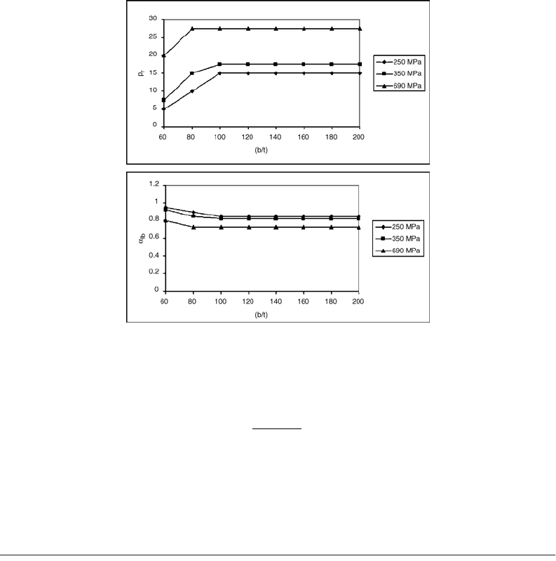
where the percentage reduction, p
r
, is given as
(51.87)
By determining N
c
using an existing standard, one can include the effects of local buckling by deter-
mining a
lb
. The global buckling load N
clb
can be determined using Eq. (51.84). The reduction factors
may be determined using Fig. 51.48.
51.9 Lateral Load Resisting Systems
This section discusses four classical lateral load resisting systems for multistory building frames. They
are the (1) core braced system, (2) moment–truss system, (3) outrigger and belt system, and (4) tube
system. Multistory buildings that utilize cantilever action will have higher efficiencies, but the overall
structural efficiency depends on the height-to-width ratio. Interactive systems involving a moment frame
and vertical truss or core are effective up to 40 stories and represent most building forms for tall structures.
Outrigger and belt trusses help to further enhance the lateral stiffness by engaging the exterior frames
with the core braces to develop cantilever actions. Exterior framed tube systems with closely spaced
exterior columns connected by deep girders mobilize the three-dimensional action to resist lateral and
torsional forces. Bundled tubes improve the efficiency of exterior frame tubes by providing internal
stiffening to the exterior tube. Finally, by providing diagonal braces to the exterior framework, a super-
frame is formed and can be used for ultratall megastructures. Further details on the comparison of
various framing schemes are reported in Liew et al. [39].
Core Braced Systems
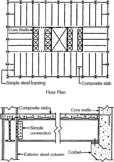
This type of structural system relies entirely on the internal core for lateral load resistance. The basic
concept is to provide an internal shear wall core to resist the lateral forces (Fig. 51.49). The surrounding
FIGURE 51.48 Interaction buckling of composite columns. From Vrcelj, Z. and Uy, B., J. Construct. Steel Res., 2001.
p
NN
N
r
c clb
c
=
-
Ê
Ë
Á
ˆ
¯
˜
*100
© 2003 by CRC Press LLC
Composite Steel–Concrete Structures 51-51
steel framing is designed to carry a gravity load only if simple framing is adopted. Otherwise, a rigid
framing surrounding the core will enhance the overall lateral force resistance of the structure. The steel
beams can be simply connected to the core walls by using a typical corbel detail, by bearing in a wall
pocket, or by using a shear plate embedded in the core wall through studs. If rigid connection is required,
the steel beams should be rigidly connected to the steel columns embedded in the core wall. Rigid framing
surrounding the cores is particularly useful in high seismic areas and for very tall buildings that tend to
attract stronger wind loads. They act as moment frames and provide resistance to some part of the lateral
loads by engaging the core walls in the building.
The core generally provides all torsional and flexural rigidity and strength, with no participation from
the steel system. Conceptually, the core system should be treated as a cantilever wall system with punched
openings for access. The floor framing should be arranged in such a way that it distributes enough gravity
load to the core walls so that their design is controlled by compressive stresses, even under wind loads.
The geometric location of the core should be selected so as to minimize eccentricities for lateral load.
The core walls need to have adequate torsional resistance for possible asymmetry of the core system,
where the center of the resultant shear load is acting at an eccentricity from the center of the lateral force
resistance.
A simple cantilever model should be adequate to analyze a core wall structure. However, if the structural
form is a tube with openings for access, it may be necessary to perform a more accurate analysis to
include the effect of openings. The walls can be analyzed by a finite element analysis using thin-walled
plate elements. An analysis of this type may also be required to evaluate torsional stresses when the
vertical profile of the core wall assembly is asymmetrical.
The concrete core walls can be constructed using slip-form techniques, where the core walls could be
advanced several floors (typically four to six stories) ahead of the exterior steel framing. The core wall
system represents an efficient type of structural system up to a certain height premium because of its
FIGURE 51.49 Core braced frame: (a) internal core walls with simple exterior framing, (b) beam-to-wall and beam-
to-exterior column connections.
© 2003 by CRC Press LLC
51-52 The Civil Engineering Handbook, Second Edition
cantilever action. However, when it is used alone, the massiveness of the wall structure increases with
height, thereby inhabiting the free planning of interior spaces, especially in the core. The space occupied
by the shear wall leads to loss of overall floor area efficiency, compared to the tube system, which could
otherwise be used.
In commercial buildings where floor space is valuable, the large area taken up by a concrete column
can be reduced by the use of an embedded steel column to resist the extreme loads encountered in tall
buildings. Sometimes, particularly at the bottom open floors of a high-rise structure, where large open
lobbies or atriums are utilized as part of the architectural design, a heavy embedded steel section as part
of a composite column is necessary to resist high load and because of the large unbraced length. A heavy
steel section in a composite column is often utilized where the column size is restricted architecturally
and where reinforcing steel percentages would otherwise exceed the code’s maximum allowed values for
the design of reinforced concrete columns.
Moment–Truss Systems
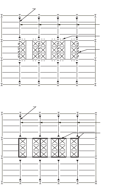
Vertical shear trusses located around the inner core in one or both directions can be combined with
perimeter moment-resisting frames in the facade of a building to form an efficient structure for lateral
load resistance. An example of a building consisting of moment frames with shear trusses located at the
center is shown in Fig. 51.50(a). For the vertical trusses arranged in the North–South direction, either
the K or X form of bracing is acceptable, since access to lift shafts is not required. However, K trusses
FIGURE 51.50 (a) Moment frame with internal braced trusses. (b) Moment frame with internal core walls.
Moment connection
typical
Moment
frames
Knee
bracing
X or K
bracing
(a)
Moment connection
typical
Moment
frames
Concrete
walls
(b)
© 2003 by CRC Press LLC
Composite Steel–Concrete Structures 51-53
are often preferred, because in the case of the X or single-brace form, bracing the influence of gravity
loads is rather significant. In the East–West direction, only knee bracing is effective in resisting lateral load.
In some cases internal bracing can be provided using concrete shear walls, as shown in Fig. 51.50(b).
The internal core walls substitute the steel trusses in K, X, or single-brace form, which may interfere with
openings that provide access to, for example, elevators.
The interaction of shear frames and vertical trusses produces a combination of two deflection curves
with the effect of more efficient stiffness. These moment frame–truss interacting systems are considered
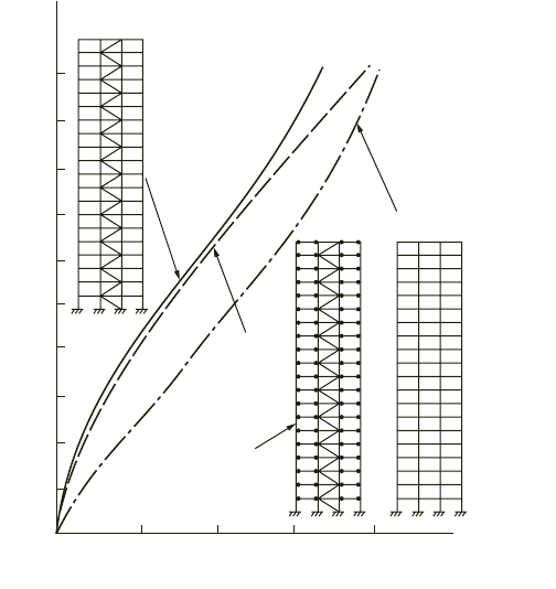
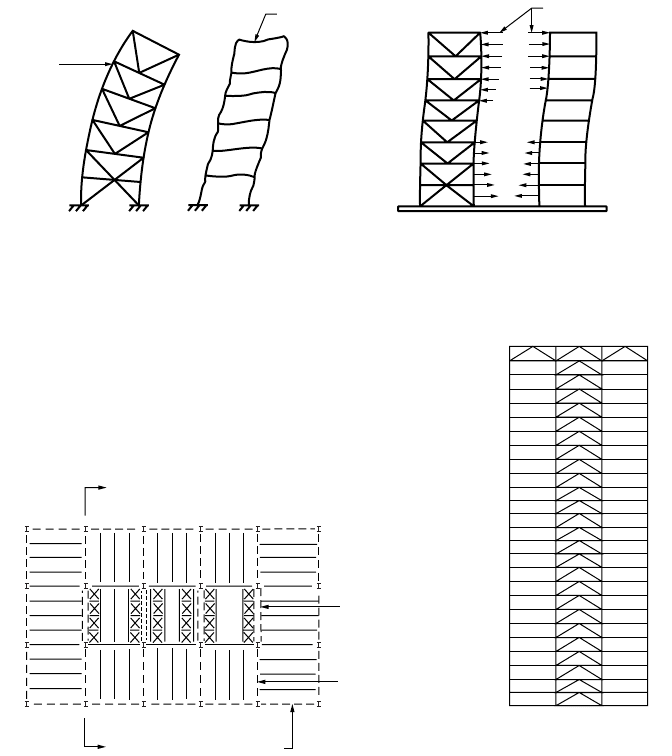
to be the most economical steel systems for buildings up to 40 stories. Figure 51.51 compares the sway
characteristic of a 20-story steel frame subjected to the same lateral forces, but with different structural
schemes, namely, (1) unbraced moment frame, (2) simple truss frame, and (3) moment–truss frame.
The simple truss frame helps to control lateral drift at the lower stories, but the overall frame drift
increases toward the top of the frame. The moment frame, on the other hand, shows an opposite
characteristic for side sway, compared with the simple braced frame. The combination of the moment
frame and the truss frame provides overall improvement in reducing frame drift; the benefit becomes
more pronounced toward the top of the frame. The braced truss is restrained by the moment frame at
the upper part of the building, while at the lower part, the moment frame is restrained by the truss frame.
This is because the slope of frame sway displacement is relatively smaller than that of the truss at the
top, while the proportion is reversed at the bottom. The interacting forces between the truss frame and
moment frame, as shown in Fig. 51.52, enhance the combined moment–truss frame stiffness to a level
larger than the summation of individual moment frame and truss stiffness.
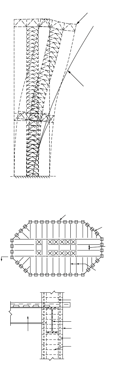
Outrigger and Belt Truss Systems
Another significant improvement of lateral stiffness can be obtained if the vertical truss and the perimeter
shear frame are connected on one or more levels by a system of outrigger and belt trusses. Figure 51.53
shows a typical example of such a system. The outrigger truss leads the wind forces of the core truss to
FIGURE 51.51 Sway characteristics of rigid braced, simple braced, and rigid unbraced frames.
20
18
16
14
12
10
8
6
4
2
0
0510
Simple
connections
Simple
truss
frame
Unbraced moment frame
Moment−truss frame
15 20
Story number
Lateral deflection (cm)
© 2003 by CRC Press LLC
51-54 The Civil Engineering Handbook, Second Edition
the exterior columns, providing cantilever behavior of the total frame system. The belt truss in the facade
improves the cantilever participation of the exterior frame and creates a three-dimensional frame behavior.
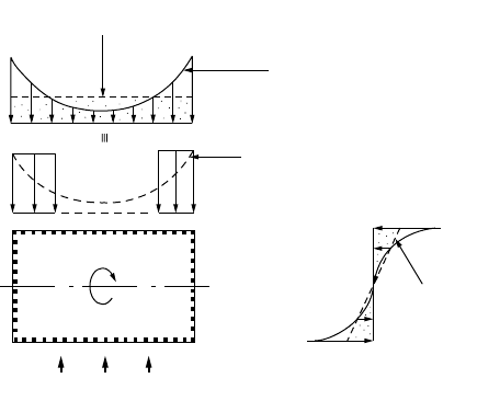
Figure 51.54 shows a schematic diagram that demonstrates the sway characteristic of the overall
building under lateral load. Deflection is significantly reduced by the introduction of the outrigger–belt
trusses. Two kinds of stiffening effects can be observed: one is related to the participation of the external
columns, together with the internal core, to act in a cantilever mode; the other is related to the stiffening
of the external facade frame by the belt truss to act as a three-dimensional tube. The overall stiffness can
be increased up to 25%, compared to the shear truss and frame system without such outrigger–belt
trusses.
The efficiency of this system is related to the number of trussed levels and the depth of the truss. In
some cases the outrigger and belt trusses have a depth of two or more floors. They are located in service
floors where there are no requirements for wide open spaces.
Frame Tube Systems
Figure 51.55 shows a typical frame tube system, which consists of a frame tube at the exterior of the
building and gravity steel framing at the interior. The framed tube is constructed from large columns
FIGURE 51.52 Behavior of frames subjected to lateral load: (a) independent behavior, (b) interactive behavior.
FIGURE 51.53 Outrigger and belt truss system.
(b)
(a)
Braced
frame
Moment frame
Interacting forces
Shear
truss
Outrigger
truss
Belt truss
a
a
Section a - a
© 2003 by CRC Press LLC
Composite Steel–Concrete Structures 51-55
FIGURE 51.54 Improvement of lateral system using outrigger and belt trusses.
FIGURE 51.55 Composite tube system.
Sway with core
truss + outrigger
Sway with core
truss alone
xxxx
x
x
x
(b)
Steel column
Erection column
Steel spandrel
Composite column
Column vertical reinforcement
Column ties
Floor beam
(a)
X
Composite column
Steel
spandrel
Concrete topping
on composite
metal deck
Gravity steel
framing
© 2003 by CRC Press LLC
51-56 The Civil Engineering Handbook, Second Edition
placed at close centers connected by deep beams, creating a punched-wall appearance. The exterior frame
tube structure resists all lateral loads of wind or earthquake, whereas the simple steel framing in the
interior resists only its share of gravity loads. The behavior of the exterior frame tube is similar to that
of a hollow perforated tube. The overturning moment under the action of lateral load is resisted by
compression and tension of the leeward and windward columns. The shear is resisted by bending of the
columns and beams at the two sides of the building parallel to the direction of the lateral load.
Deepening on the shear rigidity of the frame tube, there may exist a shear lag across the windward
and leeward sides of the tube. As a result, not all flange columns resist the same amount of axial force.
An approximate approach is to assume an equivalent column model, as shown in Fig. 51.56. In the
calculation of the lateral deflection of the frame tube it is assumed that only the equivalent flange columns
on the windward and leeward sides of the tube and the web frames would contribute to the moment of
inertia of the tube.
The use of an exterior framed tube has two distinct advantages: (1) it develops high rigidity and
strength for torsional and lateral load resistance, since the structural components are effectively placed
at the exterior of the building, forming a three-dimensional closed section; and (2) the massiveness of
frame tube system eliminates potential uplift difficulties and produces better dynamic behavior. The use
of simple steel framing in the interior has the advantage of flexibility and enables rapid construction.
Composite columns are commonly used in the perimeter of the building where the closely spaced
columns are rigidly connected by deep spandrel beams to form a three-dimensional cantilever tube. The
exterior frame tube significantly enhances the structural efficiency in resisting lateral loads and thus
reduces the shear wall requirements. However, in cases where a higher magnitude of lateral stiffness is
required (such as for very tall buildings), internal wall cores and interior columns with floor framing
can be added to transform the system into a tube-in-tube system. The concrete core may be strategically
located to recapture elevator space and to provide transmission of mechanical ducts from shafts and
mechanical rooms.
Steel–Concrete Composite Systems
Steel–concrete composite construction has gained wide acceptance as an alternative to pure steel and
pure concrete construction. Composite building systems can be broadly categorized into two forms: one
utilizes the core braced system by means of interior shear walls, and the other utilizes exterior framing
to form a tube for lateral load resistance. Combining these two structural forms will enable taller buildings
to be constructed.
FIGURE 51.56 Shear lag effect in a frame tube system.
Distribution
without
shear lag
Distribution without
shear lag
Actual axial
stress
distribution
Equivalent
axial stress
M
Lateral force
© 2003 by CRC Press LLC
Composite Steel–Concrete Structures 51-57
For composite frames resisting gravity load only, the beam-to-column connections behave as they do
when pinned before the placement of concrete. During construction, the beam is designed to resist
concrete dead load and the construction load (to be treated as a temporary live load). At the composite
stage, the composite strength and stiffness of the beam should be utilized to resist the full design loads.
For simple frames consisting of bare steel columns and composite beams, there is now sufficient knowl-
edge available for the designer to use composite action in the structural element, as well as the semirigid
composite joints, to increase design choices, leading to more economical solutions. Practical design
guidelines for semicontinuous composite braced frames are given in Liew et al. [40]. Deflection equations
are derived, and vibration studies were conducted.
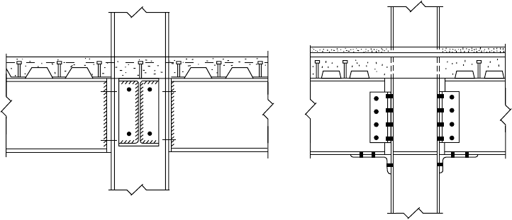
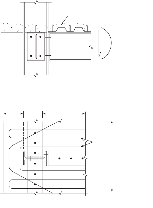
Figure 51.57 shows two typical beam-to-column connections: one using a flushed end plate bolted to
the column flange, and the other using a bottom angle with double web cleats. Composite action in the
joint is developed based on the tensile forces in the rebars that act with the balancing compression forces
transmitted by the lower portion of the steel section that bears against the column flange to form a
couple. Properly designed and detailed composite connections are capable of providing moment resis-
tance up to the hogging resistance of the connecting members.
In designing the connections, slab reinforcements placed within a horizontal distance of six times the
slab depth are assumed to be effective in resisting the hogging moment. Reinforcement steels that fall
outside this width should not be considered in calculating the resisting moment of the connection (see
Fig. 51.58). The connections to edge columns should be carefully detailed to ensure adequate anchorage
of rebars. Otherwise, they shall be designed and detailed as simply supported. In braced frames a moment
connection to the exterior column will increase the moments in the column, resulting in an increase of
column size. Although the moment connections restrain the column from buckling by reducing the
effective length, this is generally not adequate to offset the strength required to resist this moment.
For an unbraced frame subjected to gravity and lateral loads, the beam is typically bent in double
curvature with hogging moment at one end of the beam and sagging moment at the other. The concrete
is assumed to be ineffective in tension; therefore, only the steel beam stiffness on the hogging moment
region and the composite stiffness on the sagging moment region can be utilized for frame action. The
frame analysis can be performed with variable moments of inertia for the beams, and the second-order
effect can be included in the advanced analysis [41].
If semirigid composite joints are used in unbraced frames, the flexibility of the connections will
contribute to additional drift over that of a fully rigid frame. In general, semirigid connections do not
require the column size to be increased significantly over an equivalent rigid frame. This is because the
design of frames with semirigid composite joints takes advantage of the additional stiffness in the beams
provided by the composite action. The increase in beam stiffness would partially offset the additional
flexibility introduced by the semirigid connections.
FIGURE 51.57 Composite connections.
© 2003 by CRC Press LLC
51-58 The Civil Engineering Handbook, Second Edition
Methods for an accurate modeling of effective stiffness of composite members in unbraced frames,
including second-order effects, are reported in Liew and Uy [42]. Advanced analysis for modeling beam-
to-column semirigid connections, steel frames, and concrete core wall interaction is reported in Liew [43].
Further research is required to assess the performance of various types of composite connections used
in building structures with mixed systems.
Notation
FIGURE 51.58 Tr ansferring of moment through slab reinforcement at perimeter columns.
A
c
Area of concrete
A
r
Area of reinforcement
A
s
Area of steel section
A
w
Web area of steel section
B
1
,
B
2
Factors used in determining M
n
for combined bending and axial forces when elastic, first-
order analysis is employed
b Breadth of steel section
b
c
Overall breadth of composite column
c
1
, c
2
,
c
3
Numerical coefficients
c
r
Thickness of concrete cover
D
o
Outer diameter of circular hollow steel section
d Depth of steel section
U bars
(a) Connection detail
(b) Reinforcement detail
Projection ≥ 0.2L ≥150
U bars
Effective breadth
of slab ≤6D
s
at
edge columns
© 2003 by CRC Press LLC
Composite Steel–Concrete Structures 51-59
E
a
Modulus of elasticity of steel section
E
c
Modulus of elasticity of concrete for long term
E
cd
Modulus of elasticity of concrete for short term
E
cm
Secant modulus of the concrete
E
s
Modulus of elasticity of reinforcement
e Eccentricity of applied loading
e
o
Initial imperfection
(EI)
e
Effective elastic flexural stiffness of a composite cross section
F Force in the element
F
v
Average shear force
f
cc
Characteristic strength of concrete due to confinement effect
f
cd
Design strength of concrete
f
ck
Characteristic cylinder strength of concrete
f
cu
Characteristic cube strength of concrete
f
sd
Design strength of reinforcement
f
sk
Nominal yield strength of reinforcement
f
u
Ultimate strength of the shear connector
f
y
Characteristic strength of reinforcement
f
yd
Design strength of steel section
G
a
Shear modulus of steel
h
c
Overall width of composite column
h
1
Concrete width perpendicular to plane of bending
h
2
Concrete thickness in plane of bending
I
a
Second moment of area of steel section
I
c
Second moment of concrete
I
s
Second moment of area reinforcement
L Length of column
l
e
Effective length of column
M
a.Sd
Design moment applied to steel section
M
c
Moment capacity of composite section
M
cs.Sd
Design moment applied to concrete and reinforcement
M
lt
Required flexural strength in member due to lateral frame transition
M
n
Required flexural strength of column
M
nt
Required flexural strength in member, assuming there is no lateral transiton of frame
M
pl.c.Rd
Plastic moment resistance of concrete and reinforcement
M
pl.Rd
Plasic moment resistance of the composite cross section
M
s
Plastic moment capacity of steel beam alone
M
Sd
Design moment applied to composite column
M
u
Moment capacity of column
N
a.Rd
Resistance to compression of steel section
N
a.Sd
Design axial load applied to steel section
N
cr
Elastic buckling load of column
N
cr.L
Elastic critical load of composite column based on system length
N
cs.Sd
Design axial load applied to concrete and reinforcement
N
G.Sd
Part of the design load acting permanently on column
N
pl.R
Plastic resistance of composite column
N
pl.Rd
Resistance to compression of composite cross section
N
Sd
Design axial force of column
N
u
Squash load of column
P
Rd
Design resistance of headed-stud connector
p
y
Design strength of structural steel (N/mm
2
)
r
m
Modified radius of gyration of steel shape, pipe, or tubing in composite columns
r
y
Radius of gyration of a member about its minor axis
© 2003 by CRC Press LLC