Wai-Fah Chen.The Civil Engineering Handbook
Подождите немного. Документ загружается.

51-40 The Civil Engineering Handbook, Second Edition
•The expressions may be obtained by combining the stress distributions of the cross section at
points B and C. The compression area of the concrete at point B is equal to the tension area of
the concrete at point C. The moment resistance at point C is equal to that at point B, since the
stress resultants from the additionally compressed parts nullify each other in the central region
of the cross section. However, these additionally compressed regions create an internal axial force,
which is equal to the plastic resistance to compression of the concrete alone, N
pm.Rd
.
•At point D, the plastic neutral axis coincides with the centroidal axis of the cross section and the
resulting axial force is half of that at point C:
•Point E is midway between points A and C. It is often required for highly nonlinear interaction
curves, in order to achieve better approximation. In general, it is not needed for concrete-encased
I sections subject to moments about the major axis, or if the design axial force does not exceed
N
pm.Rd
. For concrete-filled hollow sections, the use of point E will give more economical design,
although much calculation effort is required. For simplicity, point E may be omitted in design.
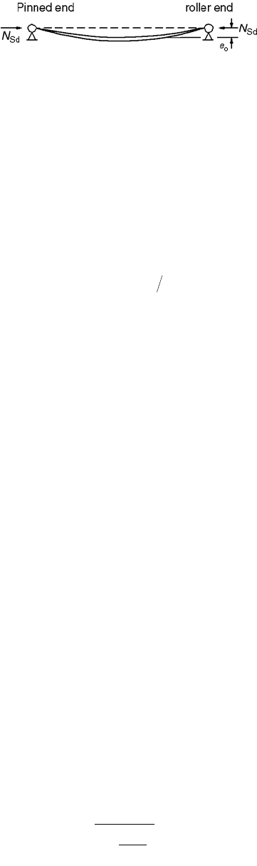
Analysis of Bending Moments Due to Second-Order Effects
Under the action of a design axial load N
Sd
on a column with an initial imperfection e
o
, as shown in
Fig. 51.41, there will be a maximum internal moment of N
Sd
(e
o
). It is important to note that this second-
order moment does not need to be considered separately, as its effect on the buckling resistance of the
composite column is already accounted for in the European buckling curves, as shown in Fig. 51.37(c).
However, in addition to axial forces, a composite column may be also subjected to end moments as a
consequence of transverse loads acting on it, or because the composite column is part of a frame. The
moments and displacements obtained initially are referred to as first-order values. For slender columns,
the first-order displacements may be significant, and additional or second-order bending moments may
be induced under the actions of applied loads. As a simple rule, the second-order effects should be
considered if the buckling length-to-depth ratio of a composite column exceeds 15.
The second-order effect on the bending moment for isolated nonsway columns should be considered
when both of the following conditions are satisfied:
1. N
Sd
/N
cr
> 0.1, where N
Sd
is the design applied load and N
cr
is the elastic critical load of the composite
column.
2. l > 0.2(2 – r), where l is the nondimensional slenderness of the composite column and r is the
ratio of the smaller to the larger end moment. If there is any transverse loading, r should be taken
as 1.0.
The second-order effects in an isolated nonsway column may be allowed for by multiplying the
maximum first-order bending moment M
max.Sd
with a correction factor k, which is defined as
(51.59)
FIGURE 51.41 Initially imperfect column under axial compression.
NN
MM
D pm.Rd
C max.Rd
=
=
2
k
N
N
Sd
cr L
=
-
Ê
Ë
Á
ˆ
¯
˜
≥
b
1
10
.
.
© 2003 by CRC Press LLC
Composite Steel–Concrete Structures 51-41
where N
Sd
= the design axial load
N
cr.L
= the elastic critical load of the composite column based on the system length, L
b = an equivalent moment factor
For columns with transverse loading within the column length, the value for b should be taken as 1.0.
For pure end moments, b is determined as follows:
b = 0.66 + 0.44r ≥ 0.44 (51.60)
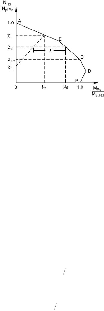
Resistance of Members under Combined Compression and Uniaxial Bending
The principle for checking sections under compression and uniaxial bending is shown graphically in
Fig. 51.39 or 51.42. In this method an initial imperfection has been incorporated, so that any additional
consideration of geometrical imperfection is unnecessary in the calculations of moments within the
column length.
The axial resistance of the composite column in the absence of moment is given by cN
pl.Rd
(refer to
Eq. (51.46)). Therefore, at the level c = N
Rd
/N
pl.Rd
, no additional bending moment can be applied to the
column. The corresponding value for bending m
k
of the cross section is therefore the moment for
imperfection of the column, and the influence of this imperfection is assumed to decrease linearly to the
value c
n
. For an axial load ratio less than c
n
, the effect of imperfections is neglected.
It is important to recognize that the value c
n
accounts for the fact that the influences of the imper-
fections and bending moment do not always act together unfavorably. For columns with end moments,
c
n
may be obtained as follows:
(51.61)
If transverse loads occur within the column height, r is taken as unity and c
n
is thus equal to zero.
With a design axial load of N
Sd
, the axial load ratio c
d
is defined as
(51.62)
The horizontal distance from the interaction curve, m, defines the ultimate moment resistance that is
still available, having taken account of the influence of second-order effects in the column.
EC4 considers that the design is adequate when the following condition is satisfied:
M
Sd
£ 0.9 mM
pl.Rd
(51.63)
FIGURE 51.42 Interaction curve for compression and uniaxial bending using EC4 method.
cc
n
=-
()
14r
c
dSdpl.Rd
= NN
© 2003 by CRC Press LLC
51-42 The Civil Engineering Handbook, Second Edition
where M
Sd
= the design bending moment, which may be factored to allow for second-order effects, if any
m = the moment resistance ratio obtained from the interaction curve
M
pl.Rd
= the plastic moment resistance of the composite cross section
The interaction curve has been determined without considering the strain limitations in the concrete.
Hence the moments, including second-order effects if necessary, are calculated using the effective elastic
flexural stiffness (EI)
e
and taking into account the entire uncracked concrete area of the cross section
(i.e., concrete is uncracked). Consequently, a reduction factor of 0.9 is applied to the moment resistance
in Eq. (51.63) to allow for the simplifications in the approach.
In certain regions of the interaction curve, the moment resistance ratio is allowed to be greater than
the unity in the presence of an axial load. This is due to the fact that in the presence of an axial load,
the amount of concrete in tension and thus area of cracked section is reduced, and more concrete is
included in the evaluation of the moment resistance. However, if the bending moment and applied load
are independent of each other, the value of m must be limited to 1.0.
For concrete-filled hollow sections, inclusion of point E in the interaction curve, as shown in Fig. 51.42,
will give more economical design, especially for columns under a high axial load and low end moments.
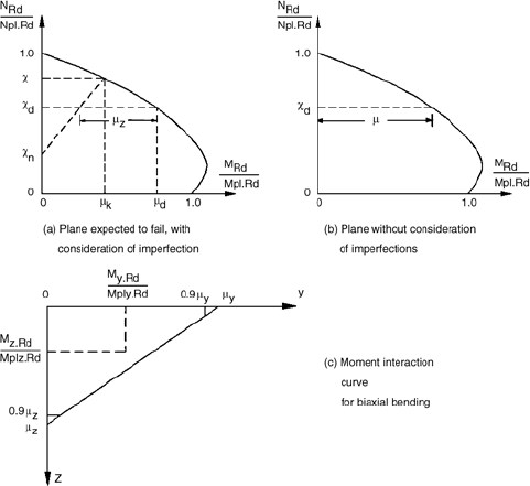
Combined Compression and Biaxial Bending
For the design of a composite column under combined compression and biaxial bending, the axial
resistance of the column in the presence of the bending moment for each axis must be evaluated separately.
In general, it will be obvious which axis is more critical. If not, checks have to be carried out for
compression and uniaxial bending for each axis separately. Imperfections should be considered only for
the plane in which failure is expected to occur.
After finding the moment resistance ratios m
y
and m
z
for both axes, the interactions of the moments
are checked using the moment interaction curve shown in Fig. 51.43. This linear interaction curve is cut
off at 0.9m
y
and 0.9m
z
. The design moments M
y.Sd
and M
z.Sd
, related to the respective plastic moment
resistances, must lie within the moment interaction curve.
EC4 considers the check adequate when all of the following conditions are satisfied:
FIGURE 51.43 Design for combined compression and biaxial bending.
© 2003 by CRC Press LLC

Composite Steel–Concrete Structures 51-43
(51.64)
(51.65)
and
(51.66)
In columns with a different distribution of moments in both of the main axes, the determination of
the position of the critical combination of moments is often very difficult. For the purpose of simplifi-
cation, the maximum moments of the bending axes may be used in Eq. (51.66).
AISC-LRFD
The concept of applying AISC-LRFD column design methodology to composite columns by the use of
modified properties was first presented by Furlong [32]. Modified yield stress F
my
, modified modulus of
elasticity E
m
, and modified radius of gyration r
m
were incorporated into an allowable stress design
procedure that was published by Task Group 20 of the Structural Stability Research Council [33].
Axially Loaded Column
When a column is under axial compression, concrete spalls and fails when longitudinal strain reaches
about 0.18 to 0.20%. Cross section strength P
o
is the sum of axial load capacities of the materials that
make up the cross section. Thus, for steel that yields at strains no greater than 0.2%,
P
o
= A
s
F
y
+ A
r
F
yr
+ 0.85A
c
f
c
¢ (51.67)
where A
s
= the area of structural shape in the cross section
A
r
= the area of longitudinal reinforcement in the cross section
A
c
= the concrete in the cross section
F
y
= the yield strength of the structural shape steel
F
yr
= the yield strength of the longitudinal reinforcement
f
c
¢
= the strength of concrete from standard cylinder tests
The design strength of composite columns is determined from the same equations as those applicable
to bare steel columns, except that the formulas are entered with modified properties F
my
, E
m
, and r
m
. The
axial design strength is computed as
f
c
P
n
= 0.85A
s
F
cr
(51.68)
where F
cr
is the critical stress of the column given by Eqs. (51.69) and (51.70). Both equations include
the estimate effects of residual stresses and initial of-out-straightness of the members. The factor 0.877
in Eq. (51.70) accounts for the effect of member initial out-of-straightness.
(51.69)
and
(51.70)
M
M
ySd
y Ply Rd
.
.
.
m
£ 09
M
M
zSd
z Plz Rd
.
.
.
m
£ 09
M
M
M
M
ySd
y Ply Rd
zSd
z Plz Rd
.
.
.
.
.
mm
+£10
FF
cr my
=
()
£0 658 1 5
2
..
l
l
c
for
c
FF
cr my
=>
0 877
15
.
.
l
l
c
2
c
for
© 2003 by CRC Press LLC
51-44 The Civil Engineering Handbook, Second Edition
where F
my
= the modified yield stress and l
c
= (KL/r
m
p)÷(F
my
/E
m
), in which E
m
is the modified modulus
of elasticity, r
m
is the modified radius of gyration about the axis of buckling, K is the effective length
factor, and L is the laterally unbraced length of a member.
The modified properties F
my
, E
m
, and r
m
account for the effects of concrete and longitudinal reinforcing
bars. The modified radius of gyration r
m
is the radius of gyration of the steel section, and it shall not be
less than 0.3 times the overall thickness of the composite cross section in the plane of buckling. The
modified values F
my
and E
m
are given by the following equations:
(51.71)
and
(51.72)
where F
y
= the yield strength of structural steel, £60 ksi (414 MPa)
F
yr
= the yield strength of longitudinal reinforcement, £60 ksi (414 MPa)
E = the modulus of elasticity of steel
E
c
= the modulus of elasticity of concrete
c
1
, c
2
, and c
3
= the numerical coefficients listed in Table 51.10
Coefficients c
1
, c
2
, and c
3
are higher for filled composite columns than for encased composite columns.
With the steel encasement always available to provide lateral confinement to concrete in filled composite
columns, there is no uncertainty that the contained concrete will reach at least as much strength as that
reached by concrete in unconfined standard concrete cylinders used in determining f
c
¢. In contrast, there
is less uncertainty that an unconfined concrete encasement can attain stress as high as 0.85f
c
¢. If the
unconfined concrete fails to reach 0.85f
c
¢, the longitudinal reinforcement it stabilizes may not reach its
yield stress, F
yr
, either. The values of c
1
and c
2
for encased composite columns are 70% of the values for
filled composite columns, reflecting the higher degree of uncertainty.
To account for the uncertainty regarding the contribution of concrete to the buckling strength of a
composite column, Eq. (51.72) includes the numerical coefficient c
3
, which is equal to 0.4 for filled
composite columns and 0.2 for encased composite columns. These coefficients are consistent with values
recommended in the ACI building code for flexural stiffness, EI, in estimates of inelastic buckling loads.
Concrete loses stiffness at strains near 0.2% and may not be fully effective for stabilizing steel at strains
higher than 0.2%, which translates into steel–stress values of about 60 ksi (414 MPa). The yield stresses
of structural steel (F
y
) and reinforcing bars (F
yr
) used in calculating the strength of composite columns
should not exceed 60 ksi. It is further recommended that the concrete strength f
c
¢ be limited to 10 ksi
(69 MPa) and smaller, since only very few tests are available for composite columns with f
c
¢ in excess of
10 ksi. A lower limit of f
c
¢ = 2.5 ksi (17 MPa) is recommended in order to encourage a degree of quality
control commensurate with this readily available and familiar grade of structural concrete.
Flexural Strength
The nominal flexural strength, M
n
, of a column cross section may be determined from the plastic state
of stress or from an analysis of flexural strength at the ultimate state of strain. For simplicity, the
TA BLE 51.10 Numerical Coefficients for Design
of Composite Columns
Numerical Coefficients
Composite Column Type c
1
c
2
c
3
Concrete-filled pipe and tubing 1.0 0.85 0.4
Concrete-encased shapes 0.7 0.6 0.2
FF
cF A
A
cfA
A
my y
yr r
s
cc
s
=+ +
¢
1
2
EE
cEA
A
m
cc
s
=+
3
© 2003 by CRC Press LLC

Composite Steel–Concrete Structures 51-45
commentary in the AISC-LRFD (Section C-I4) offers an approximate equation for moment capacity of
doubly symmetric sections. The sum of flexural capacities for component parts includes the plastic
moment capacity of the steel shape, an estimate of the yield moment of reinforcement, and the moment
capacity for which compression concrete is considered reinforced at middepth by longitudinal bars and
the web of the steel shape.
(51.73)
where A
w
= the web area of steel shape plus any longitudinal bars at the center of the section
Z = the plastic section modulus of the steel shape
h
1
= the concrete width perpendicular to the plane of bending
h
2
= the concrete thickness in the plane of bending
c
r
= the thickness of concrete cover from the center of bar to the edge of the section in the
plane of bending
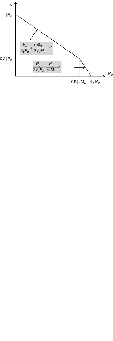
Combined Axial Compression and Moments
For composite columns symmetrical about the plane of bending, the interaction of compression and
flexure should be limited by the formulas in the following AISC-LRFD equations:
(51.74)
and
(51.75)
where P
u
= the required compressive strength
P
n
= the nominal compressive strength
M
u
= the required flexural strength
M
n
= the nominal flexural strength
f
c
= the resistance factor for compression, 0.85
f
b
= the resistance factor for flexure, 0.90
and subscripts x and y denote the major and minor axes, respectively.
Second-order effects may be considered in the determination of M
u
for use in Eqs. (51.74) and (51.75).
The simplicity of AISC-LRFD results in a conservative design. The supporting comparisons with the
beam-column test, given in the commentary of AISC-LRFD, included 48 concrete-filled pipes or tubing
and 44 concrete-encased steel shapes (see Galambos and Chapuis [34]). The overall mean test-to-
prediction ratio was 1.23, and the coefficient of variation was 0.21.
Australian Standards AS 3600 and AS 4100
Strength of Short Columns
The design of a concrete-filled steel column in Australia can be undertaken using a combination of the
Australian Standards for concrete and steel structures. Thus the ultimate axial force of a column can be
represented as
N
u
= N
uc
+ N
us
(51.76)
MZF h CAF
h
AF
fh
AF
ny rryr
wy
c
wy
=+ -
()
+-
¢
Ê
Ë
Á
ˆ
¯
˜
1
3
2
217
2
2
1
.
P
P
M
M
M
M
PP
u
cn
ux
bnx
uy
bny
fff
f++
Ê
Ë
Á
ˆ
¯
˜
£ ≥
8
9
102for
ucn
.
P
P
M
M
M
M
PP
u
cn
ux
bnx
uy
bny
2
102
ff f
f++£ <for
ucn
.
© 2003 by CRC Press LLC
51-46 The Civil Engineering Handbook, Second Edition
The Australian Standard for concrete structures, AS 3600, will not allow confinement, as it does not
treat the behavior of concrete-filled steel columns directly. The concrete contribution to strength can be
determined using Eq. (51.77), where
N
uc
= 0.85A
c
f
c
(51.77)
The Australian Standard for steel structures, AS 4100, suggests a set of slenderness limits that do not
allow for the beneficial effect of local buckling. Slenderness limits for inelastic local buckling are as low
as b/t = 30 for heavily welded sections. However, this standard allows one to use a rational local buckling
method to determine the post-local buckling strength. The steel strength can therefore be determined
from Eq. (51.78), where
N
uc
= A
se
f
y
(51.78)
If one combines the concrete and steel strengths, N
uc
and N
us
, respectively, from the AS 3600 and AS
4100 analysis, the resulting ultimate axial strength can be written as
N
u
= 0.85A
c
f
c
+ A
se
f
y
(51.79)
Therefore, while the beneficial effect of the concrete is taken into account for post-local buckling, the
effect of concrete confinement is ignored; the initial slenderness limits are too stringent for use in
concrete-filled steel columns, which are economical in steel construction.
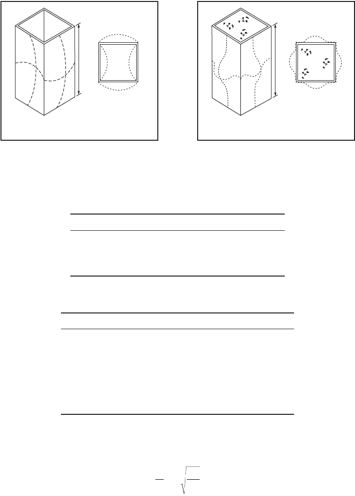
Local Buckling
If a composite section has a thin-walled steel section, which is able to buckle locally, then a reduction
for the strength of the steel section must be made. The local buckling load and strength of a concrete-
filled steel section are significantly higher than those of a hollow steel section, as shown in Fig. 51.45.
The local buckling stress can be determined using Eq. (51.80), where k is determined from a rational
local buckling analysis and is given in Table 51.11 for various boundary and fill conditions.
(51.80)
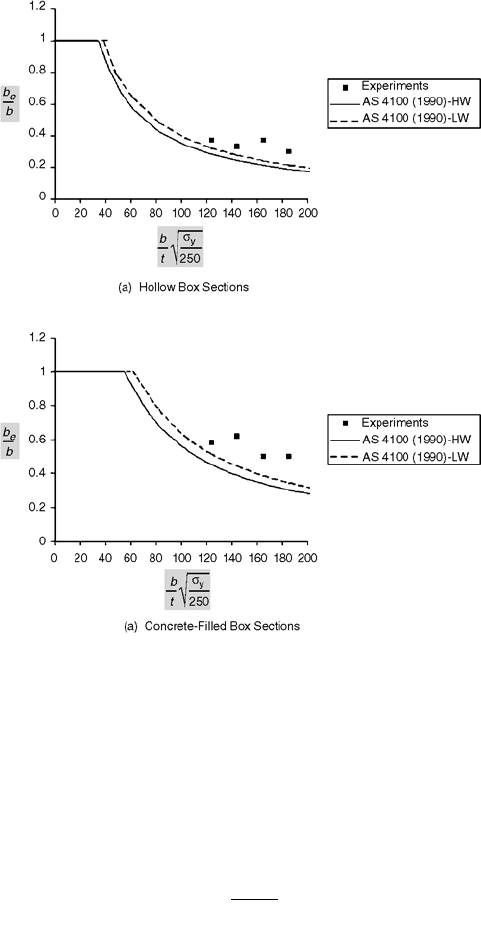
Post-Local Buckling
Post-local buckling is often predicted using the effective width concept. Effective width models for hot-
rolled and fabricated sections have been modified to incorporate residual stresses and initial imperfections
by Bradford [35] and Bradford et al. [36], and were adopted in the Australian Standard AS 4100-1990
FIGURE 51.44 Column interaction curve using AISC-LRFD (1993).
s
p
u
ol
kE
b
t
=
-
()
Ê
Ë
Á
ˆ
¯
˜
2
2
2
12 1
© 2003 by CRC Press LLC
Composite Steel–Concrete Structures 51-47
[29]. This model is based on the Winter formula, which is also present in steel codes in the U.S. and
Europe and is of the form
(51.81)
where a is a parameter used to account for residual stresses and initial geometric imperfections. This
parameter varies, depending on the type of section and its method of fabrication. Furthermore, the type
of boundary condition also affects the determination of a. Values for this parameter, including all these
factors, are summarized in Table 51.12, which was calibrated for steel structures in the Australian Standard
AS 4100-1990 [29] and reported by Bradford et al. [36]. These parameters were thus used in calibrating
the model with the post-local buckling test results determined by Uy [37] for concrete-filled sections.
The results are illustrated in Figs. (51.46) and (51.47).
FIGURE 51.45 Local buckling of box sections.
TABLE 51.11
Local Buckling Coefficient, k
Boundary Condition Type of Section k
Supported on two longitudinal edges Hollow 4.0
Supported on two longitudinal edges Filled 10.31
Supported on one longitudinal edge Hollow 0.425
Supported on one longitudinal edge Filled 2.0
TABLE 51.12 Post-Local Buckling Parameter, a
Boundary Condition Method of Manufacture a
Supported on two longitudinal edges Stress relieved 0.84
Supported on two longitudinal edges Hot rolled 0.84
Supported on two longitudinal edges Lightly welded 0.74
Supported on two longitudinal edges Heavily welded 0.65
Supported on two longitudinal edges Stress relieved 0.91
Supported on two longitudinal edges Hot rolled 0.91
Supported on two longitudinal edges Lightly welded 0.86
Supported on two longitudinal edges Heavily welded 0.80
L
(b) Local buckling
eigenmode
(a) Local buckling
half-wavelength
(a) Hollow steel section
(b) Local buckling
eigenmode
L
(a) Local buckling
half-wavelength
(b) Filled steel section
b
b
eol
y
=a
s
s
© 2003 by CRC Press LLC
51-48 The Civil Engineering Handbook, Second Edition
Strength of Slender Columns
Slender composite columns can be analyzed using either the concrete approach, AS 3600, or the steel
approach, AS 4100. The approach used by the Eurocode 4 is a useful manner in which to distinguish
between the two methods
(51.82)
The column is classified as composite if the steel contribution ratio falls within the range of 0.2 £ d £
0.9. If d is less than 0.2, the column shall be designed as a reinforced concrete column; otherwise, if d is
greater than 0.9, the column shall be designed as a bare steel column.
Concrete Approach, AS 3600
Slender columns are analyzed in the Australian Concrete Structures Code, AS 3600, using a strength
interaction diagram and a loading line. The loading line is used to account for nonlinearities and second-
order effects.
Steel Approach, AS 4100
The approach of the Australian Standard for steel columns is essentially the same as the approach of EC3
and EC4, which use the column curves with different levels of imperfections and residual stresses. The
FIGURE 51.46 Post-local buckling comparisons for box sections: (a) hollow box sections, (b) concrete-filled box
sections. From Uy, B., J. Struct. Eng. ASCE, 127, 666, 2001.
d=
Af
N
ayd
pl Rd.
© 2003 by CRC Press LLC
Composite Steel–Concrete Structures 51-49
method relies on determining a critical buckling load, N
c
, where the critical buckling load depends on
both the member slenderness and the level of imperfections and residual stresses:
N
c
= a
c
N
s
(51.83)
where a
c
is the coefficient, which depends on both member slenderness and method of manufacture. N
s
is determined based on the section capacity, which can account for local buckling. However, Vrcelj and
Uy [38] have developed a more comprehensive method to consider local buckling for concrete-filled steel
sections, and to use this method, N
s
in Eq. (51.83) is calculated as the member squash load.
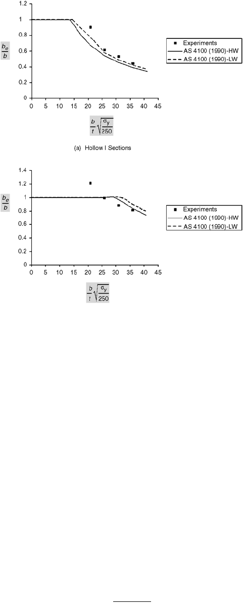
Effects of Local Buckling
The slender column buckling load, N
clb
, which incorporates local buckling, can be represented in the
form of Eq. (51.84) in terms of N
c
, the column buckling load, which ignores the effects of local buckling.
N
clb
= a
lb
N
c
(51.84)
where a
lb
is the interaction coefficient to account for local buckling and is in the range
0 £ a
lb
£ 1.0 (51.85)
and is calculated as
(51.86)
FIGURE 51.47 Post-local buckling comparisons for I sections: (a) hollow I sections, (b) concrete-filled I sections.
From Uy, B., J. Struct. Eng. ASCE, 127, 666, 2001.
a
lb
r
p
=
-
()
100
100
© 2003 by CRC Press LLC