Wai-Fah Chen.The Civil Engineering Handbook
Подождите немного. Документ загружается.

51-20 The Civil Engineering Handbook, Second Edition
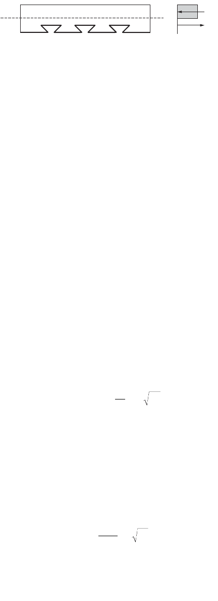
Assuming the slab is only singly reinforced, the ultimate moment, calculated by summing moments
about either the tensile force or compressive force location, is given by
M
u
= C
c
l = T
s
l (51.10)
where l is the lever arm between the compressive and tensile forces. This method of analysis, based on
the rectangular stress block principle, is the method adopted by both the British Standard (BS), BS 5950,
Part 4, and the American Standard, ANSI/ASCE 3-91. BS 5950 assumes that the concrete strength is given
by 0.4 times the cube strength and the yield strength of the steel is taken. However, this method assumes
that there exists a full shear connection between the profiled steel sheeting and the concrete in the tension
zone. This is usually the case when a sufficient mechanical and friction bond is developed for the profile
in question. Other modes of failure, which may also exist, include longitudinal slip failure and vertical
shear failure of the concrete.
Longitudinal Shear Failure
When a composite slab exhibits partial shear connection, slip of the sheeting will occur prior to the steel
sheeting yielding and the concrete crushing. The strength of the composite slab is thereby governed by
the shear bond capacity between the steel sheeting and the concrete. In many countries throughout the
world this is based on manufacturer data, and empirical methods of analysis are often applied. The reader
is referred to those methods for a more accurate method of analysis.
Vertical Shear Failure
Composite slabs may fail by vertical shear, in much the same manner as reinforced concrete slabs. For
this failure mode the maximum vertical shear capacity can be evaluated, provided sufficient test data are
available. The ultimate vertical shear strength as defined by BS 5950 is given as
(51.11)
where p is the ratio of the cross-sectional area of the profile to that of the concrete A
c
per unit width of
slab, f
cu
is the cube strength of the concrete, d
e
is the effective slab depth to the centroid of the profile,
and L
y
is the shear span length, taken as one quarter of the slab span. The constants m
d
and k
d
are
calculated from the slope and intercept, respectively, of the reduced regression line established from the
testing of composite slabs.
A similar approach is existent in the American Standard ANSI/ASCE 3-91, which relies on test data
and gives an experimentally determined shear strength as
(51.12)
The approach given in Eurocode 4 to determine the vertical shear resistance of a composite slab is
(51.13)
FIGURE 51.25 Ultimate flexural strength of a composite slab.
C
c
T
s
VAmp
d
L
kf
ucd
e
v
dcu
=+
Ê
Ë
Á
ˆ
¯
˜
08.
Vbd
md
l
kf
e
i
ct
=
¢
+
¢
Ê
Ë
Á
ˆ
¯
˜
r
Vbdk
vRd o p Rd v.
.=+
()
tr12 40
© 2003 by CRC Press LLC

Composite Steel–Concrete Structures 51-21
where b
o
= the mean width of the concrete ribs
t
Rd
= the basic shear strength to be taken as 0.25f
ctk
/g
c
(f
ctk
is the lower 5 percentile confidence
limit characteristic strength)
r =A
p
/b
o
f
p
< 0.02 (A
p
is the effective area of the steel sheet in tension)
k
v
= (1.6 – d
p
) = 1.0, with d
p
expressed in meters
Ductility
Ductility of composite slabs is also a very important consideration, although it appears that many of the
existent international codes throughout the world do not have an inherent ductility clause, which is
reflected in the design of reinforced concrete slabs. The codes investigated include BS 5950, EC4, and
ANSI/ASCE. It is suggested that in the absence of current recommendations for ductility that the following
consideration be given for the design of simply supported composite slabs, which limits the depth of the
neutral axis so that
d
n
£ 0.4d (51.14)
This is the ductility requirement for reinforced concrete slabs used in the Australian Standard for
concrete structures, AS 3600 [24], and is thus also assumed to be applicable for composite slabs to ensure
adequate ductility.
51.6 Simply Supported Beams
Simply supported composite steel–concrete beams are the original form of composite construction
developed early in the 1900s. This section will consider the design of simply supported composite beams
for serviceability, strength, and ductility. This section will mainly concentrate on the behavior of the
beam in the composite stage, as the behavior of beams in the noncomposite stage is essentially the
behavior of a steel beam, which is covered in Chapter 50 “Structural Concrete Design” of this handbook.
Serviceability
Deflections of simply supported composite beams need to incorporate the effects of both creep and
shrinkage, in addition to the loading effects. These time-dependent effects are taken into account by
generally transforming the concrete slab to an equivalent area of steel using a modular ratio. The modular
ratio should include the effects of the disparate elastic moduli, as well as the effects of creep of concrete.
Now, since the concrete is in the compression zone of simply supported composite beams in sagging
bending, the concrete is considered to be fully effective; however, the effects of shear lag need to be
determined using an effective breadth relationship. Effective widths from various international codes are
included below
AS 2327.1-1996
The effective width, b
e
, of the concrete flange for positive bending in AS 2327.1-1996 for a beam in a
regular floor system is determined as the minimum of the following
(51.15)
where L
ef
is the effective span of the composite beam, b is the width between steel beams, b
sf
is the width
of the steel flange, and D
c
is the depth of the concrete slab. For the determination of deflections in
AS 2327.1-1996, the modular ratio is determined for immediate deflections using the value (E
s
/E
c
), while
for long term deflections, a modular ratio of 3 is suggested. The effective second moments of area of
b
L
bb D
e
ef
sf c
=+
Ê
Ë
Á
ˆ
¯
˜
min , ,
4
16
© 2003 by CRC Press LLC

51-22 The Civil Engineering Handbook, Second Edition
composite beams for immediate and long-term deflections, respectively, are calculated in AS 2327.1-1996
as
(51.16)
(51.17)
where I
ti
and I
tl
are the transformed second moments of area of a composite beam under immediate and
long-term loads, respectively; b
m
is the level of shear connection, and I
s
is the second moment of area of
the steel section alone.
BS 5950, Part 3 [25]
The effective width of the concrete flange for a typical internal beam in this code should not be taken
as greater than one quarter of the distance between points of contraflexure. The imposed load deflections
in each span should be based on the loads applied to the span and the support moments for that span,
modified as recommended to allow for pattern loading and shakedown. Provided that the steel beam is
uniform without any haunches, the properties of the gross uncracked composite section should be used
throughout. (This includes the use of a modular ratio to account for long-term effects.)
Long-Term Effects (Creep and Shrinkage)
Simplified methods for determining the cross section properties in BS 5950, Part 3, involve the use of a
modular ratio. An effective modular ratio is expressed as
(51.18)
where a
1
= the modular ratio for long-term loading
a
s
= the modular ratio for short-term loading
r
1
= the proportion of the total loading, which is long term
Deflection Due to Partial Shear Connection
The increased deflection under serviceability loads arising from partial shear connection should be
determined from the following expressions:
For propped construction,
(51.19)
For unpropped construction,
(51.20)
where d
s
= the deflection of the steel beam acting alone
d
c
= the deflection of a composite beam with a full shear connection for the same loading
N
a
= the actual number of shear connectors provided
N
p
= the number of shear connectors for full composite action
Vibrations
Where vibration could cause discomfort or damage the response of long-span composite floors should
be considered using SCI Publication 076, “Design Guide on the Vibration of Floors” [23].
II II
eti ti m s ti
=+ -
()
-
()
061. b
II II
etl tl m s tl
=+ -
()
-
()
061. b
aaraa
es s
=+ -
()
11
dd d d=+ -
Ê
Ë
Á
ˆ
¯
˜
-
()
c
a
p
sc
N
N
05 1.
dd d d=+ -
Ê
Ë
Á
ˆ
¯
˜
-
()
c
a
p
sc
N
N
03 1.
© 2003 by CRC Press LLC

Composite Steel–Concrete Structures 51-23
Eurocode 4
The deflection calculation provisions of Eurocode 4-1994 are given herein. For an internal beam, the
effective width of the concrete flange for a typical internal beam in this code should not be taken as
greater than one quarter of the distance between points of contraflexure.
Long-Term Effects
In the absence of a more rigorous analysis, the effects of creep may be taken into account by using
modular ratios, as given in Section 3.1.4.2, for the calculation of flexural stiffness.
(51.21)
where E
a
is the elastic modulus of structural steel and E
c
¢ is an effective modulus of concrete. E
c
¢ = E
cm
for short-term effects, E
c
¢ = E
cm
/3 for long-term effects, and E
c
¢ = E
cm
/2 for other cases.
Deflections of Beams
Deflections of the steel beam shall be calculated in accordance with EC3. Deflections of the composite
beam shall be calculated using elastic analysis with corrections. Shear lag can be ignored for deflection
calculations, except where b > L/8, then shear lag is included by determining the effective width of the
flange according to Section 4.2.2.1. The effects of incomplete interaction may be ignored in spans or
cantilevers where critical cross sections are either class 3 or 4. The effects of incomplete interaction may
be ignored in unpropped construction, provided that shear connectors are designed according to
Chapter 6: the shear connection ratio is greater than 0.50 or the forces on the shear connectors do not
exceed 0.7P
rk
, or in the case of a ribbed slab with ribs transverse to the beam, the height of the ribs does
not exceed 80 mm. If these conditions are violated but N/N
f
= 0.4, then in lieu of testing or accurate
analysis, the increased deflection arising from incomplete interaction may be determined from the
following equations:
For propped construction,
(51.22)
For unpropped construction,
(51.23)
where d
a
= the deflection for the steel beam alone
d
c
= the deflection for the composite beam with complete interaction
N/N
f
= the degree of shear connection
Strength
The flexural strength of simply supported steel–concrete composite beams in sagging bending is deter-
mined using a rigid plastic method of analysis, where the concrete slab is assumed to be fully crushed
in compression and the steel beam is assumed to be fully yielded in tension and compression, depending
on the location of the plastic neutral axis, as well as the strength of the longitudinal shear connection.
The following cases thus may exist.
n
E
E
a
c
=
¢
d
d
d
d
cf
a
c
N
N
=+ -
Ê
Ë
Á
ˆ
¯
˜
-
Ê
Ë
Á
ˆ
¯
˜
1051 1.
d
d
d
d
cf
a
c
N
N
=+ -
Ê
Ë
Á
ˆ
¯
˜
-
Ê
Ë
Á
ˆ
¯
˜
1031 1.
© 2003 by CRC Press LLC
51-24 The Civil Engineering Handbook, Second Edition
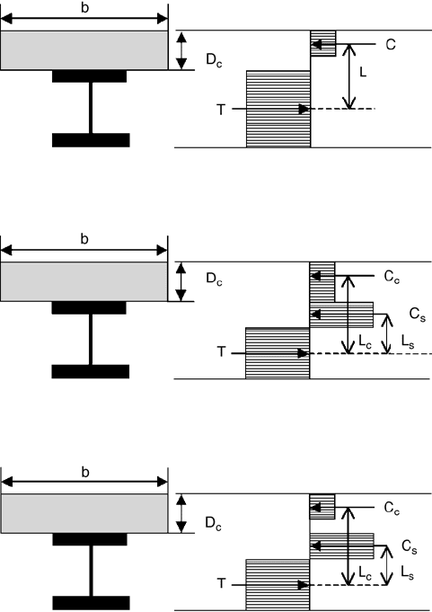
Plastic Neutral Axis in the Concrete Slab (Full Shear Connection, = 1.0)
When the concrete slab is stronger than the steel beams, the plastic neutral axis will lie within the concrete
slab. For the case when the plastic neutral axis lies within the concrete slab, the ultimate flexural strength
is determined from a simple couple, as shown in Fig. 51.26.
M
u
= TL = CL (51.24)
Plastic Neutral Axis in the Steel Beam (Full Shear Connection, = 1.0)
When the steel beam is stronger than the concrete slab, the plastic neutral axis for the beam with a full
shear connection will lie within the steel beam. For this case it is more convenient to sum the moments
about the centroid of the tension force, as illustrated in Fig. 51.27.
M
u
= C
c
L
c
= C
s
L
s
(51.25)
Partial Shear Connection ( < 1.0)
For the case of partial shear connection of composite beams, the shear connection is the weakest element.
Again, summing the moments on a convenient point on the cross section will yield the ultimate flexural
moment of the beam, as illustrated in Fig. 51.28.
M
u
= C
c
L
c
= C
s
L
s
(51.26)
FIGURE 51.26 Ultimate flexural moment, plastic neutral axis in concrete slab (b = 1.0).
FIGURE 51.27 Ultimate flexural moment, plastic neutral axis in steel beam (b = 1.0).
FIGURE 51.28 Ultimate flexural moment, partial shear connection (b < 1.0).
© 2003 by CRC Press LLC
Composite Steel–Concrete Structures 51-25
Existing International Standards
Existing international standards that deal with the flexural strength of composite beams include the
American Institute of Steel Construction Load and Resistance Design Specification (AISC-LRFD), Aus-
tralian Standards (AS 2327.1-1996), British Standards (BS 5950, Part 3), and Eurocode 4-1994. While
some of these standards have a closed-form solution for the flexural strength determination, it is best
left in a more general form, in terms of stress blocks, as shown in Figs. 51.26 to 51.28, and for individuals
to refer to the individual regional standards to determine the strength equations and apply the relevant
load and capacity reduction factors. The most general manner in which to assess the flexural strength of
a composite beam is as
M* £ fM
u
(51.27)
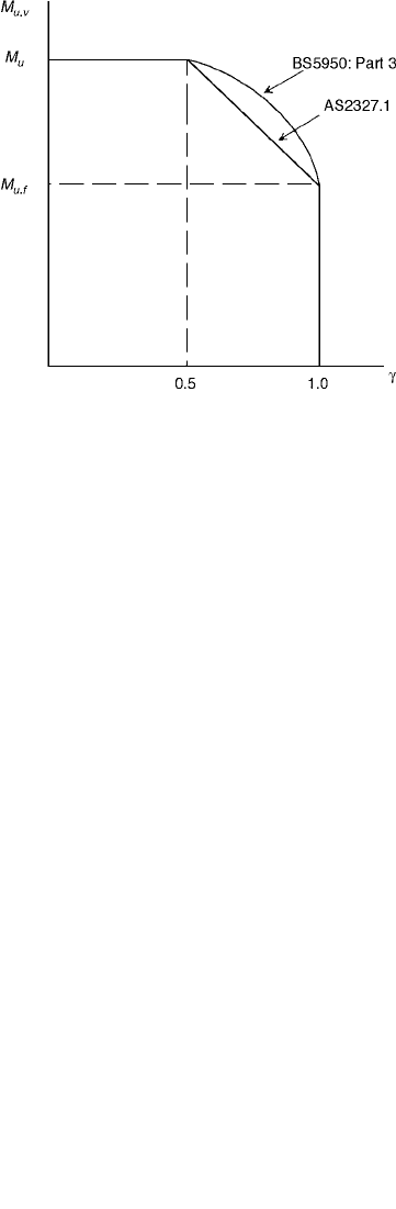
Influence of Shear on Flexural Strength
The influence of shear on the ultimate flexural strength of steel–concrete composite beams can be
significant when the relative ratio of applied shear force to shear strength is high. Most of the design
methods for this failure mode are based on test data, and an appropriate interaction equation is used by
various international standards, such as the Australian and British Standards. The Australian Standard
(AS 2327.1-1996) uses a linear relationship for reduction, which is largely based on the steel standard,
whereas the British Standard uses a quadratic expression, based on test data. Both of these relationships
are shown in Fig. 51.29.
AS 2327.1-1996:
(51.28)
BS 5950, Part 3:
(51.29)
where g = the ratio of shear force to shear strength
M
u.v
= the ultimate flexural strength incorporating shear
M
u
= the ultimate flexural strength with zero shear
M
u.f
= the ultimate flexural strength of the beam considering the flanges only
FIGURE 51.29 Influence of shear on ultimate flexural strength of composite beams.
MMMM
uv u u u f..
=- -
()
-
()
21g
MMMM
uv u u u f..
=- -
()
-
()
21
2
g
© 2003 by CRC Press LLC

51-26 The Civil Engineering Handbook, Second Edition
Ductility
None of the existing international codes have a ductility clause; however, it has been suggested by Rotter
and Ansourian [26] that in order to achieve a plastic hinge, strain hardening in the bottom flange must
develop, and from a treatment of the mechanics of the problem, they found that ductility can be
guaranteed in a simply supported beam if a ductility parameter, c, is greater than 1. The ductility
parameter is determined as
(51.30)
where f
c
= the characteristic cylinder strength
b
c
= the effective slab width
e
u
= the ultimate strain of concrete
h
conc
= the depth of the slab
h
steel
= the depth of the steel beam
A
steel
= the cross-sectional area of the steel section
f
y
= the yield strength of the steel
e
st
= the strain to cause strain hardening of the section
51.7 Continuous Beams
The design of continuous composite beams requires only an augmentation of the behavior of design of
simply supported composite beams. In particular, the salient point in regard to serviceability and strength
needs to take into account that composite beams in hogging bending behave completely differently than
beams subjected to sagging bending. This is because in hogging bending the concrete slab is subjected
to tension, and this will significantly affect both the stiffness and strength of the cross sections in hogging
moment regions.
Serviceability
When considering serviceability effects in continuous composite beams, one must include the effects of
cracking in the negative moment regions, as well as the effects of creep and shrinkage associated with
long-term loading. Since continuous beams are indeterminate, it is difficult to develop a general approach
that is amenable for design that reflects the exact behavior. Existing code methods provide a good basis
for simplifying the problem to account for the indeterminacy, as well as the nonuniform flexural rigidity,
that exists along the length of a beam. These methods will be outlined herein.
BS 5950, Part 3
Calculation of Moments
The calculation of moments for supports can be determined using the following two methods.
Pattern Loading and Shakedown — The support moments required for these cases should be based on
an elastic analysis using the properties of the gross uncracked section throughout.
Simplified Method — The moments in continuous composite beams for serviceability may be determined
using the coefficients below, provided that the following conditions are satisfied: the steel beam should
be of uniform section with no haunches; the steel beam should be of the same section in each span;
loading should be uniformly distributed; live loads should not exceed 2.5 times the dead load; no span
should be less than 75% of the longest span; end spans should not exceed 115% of the length of adjacent
spans; and there should not be any cantilevers.
c
e
ee
=
+
()
+
()
085. fb h h
Af
ccu conc steel
steel y u st
© 2003 by CRC Press LLC
Composite Steel–Concrete Structures 51-27
Support moments can then be taken as:
two-span beam: (51.31)
first support in a multispan beam: (51.32)
other internal supports: (51.33)
w is the unfactored uniformly distributed load on the span L. Where the spans on each side of a support
differ, the mean value of w is adopted.
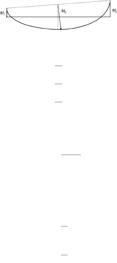
Calculation of Deflections
For continuous beams under uniform load or symmetric point loads, the deflection d
c
at midspan may
be determined from the expression:
(51.34)
where d
o
= the deflection of a simply supported beam for the same loading
M
o
= the maximum moment in the simply supported beam
M
1
and M
2
= the moments at the adjacent supports (modified as appropriate)
Partial Shear Connection
The increased deflection under serviceability loads arising from a partial shear connection should be
determined from the following expressions:
For propped construction,
(51.35)
For unpropped construction,
(51.36)
where d
s
= the deflection of the steel beam acting alone
d
c
= the deflection of a composite beam with a full shear connection for the same loading
N
a
= the actual number of shear connectors provided
N
p
= the number of shear connectors for a complete interaction
FIGURE 51.30 Bending moment distribution of a continuous beam.
wL
2
8
wL
2
10
wL
2
14
dd
co
o
MM
M
=-
+
()
Ê
Ë
Á
ˆ
¯
˜
106
12
.
dd d d=+ -
Ê
Ë
Á
ˆ
¯
˜
-
()
c
a
p
sc
N
N
05 1.
dd d d=+ -
Ê
Ë
Á
ˆ
¯
˜
-
()
c
a
p
sc
N
N
03 1.
© 2003 by CRC Press LLC
51-28 The Civil Engineering Handbook, Second Edition
Cracking
Reference is made to BS 8110 [27]. Floors in car park structures are alluded to as being of importance,
and additional reinforcement should be provided to avoid these over support regions. No consideration
for increased deflections is made due to cracking.
Vibrations
Where vibration could cause discomfort or damage the response of long-span composite floors should
be considered using SCI Publication 076, “Design Guide on the Vibration of Floors.”
Eurocode 4
Design of continuous composite beams for serviceability in EC4 is covered in Chapter 5, which is on
serviceability. Furthermore, relevant sections for internal forces and moments in continuous composite
beams are covered in Section 4.5. For stiffness calculations, modular ratios are considered in Section 3.1.4.2.
Scope
This chapter of the code covers the following limit states of deflection control and crack control. Other
limit states such as vibration may be important but are not covered in Eurocode 4.
Assumptions
Calculation of stresses and deformations at the serviceability limit state shall take into account shear lag;
incomplete interaction; cracking; tension stiffening of concrete in hogging moment regions; creep and
shrinkage of concrete; yielding of steel, if any, when unpropped; and yielding of reinforcement in hogging
moment regions.
Long-Term Effects
In the absence of a more rigorous analysis, the effects of creep may be taken into account by using
modular ratios, as given in Section 3.1.4.2, for the calculation of flexural stiffness.
(51.37)
where E
a
is the elastic modulus of structural steel and E
c
¢ is an effective modulus of concrete. E
c
¢ = E
cm
for short-term effects, E
c
¢ = E
cm
/3 for long-term effects, and E
c
¢ = E
cm
/2 for other cases.
Deformations
The effect of cracking of concrete in hogging moment regions may be taken into account by adopting
one of the following methods of analysis.
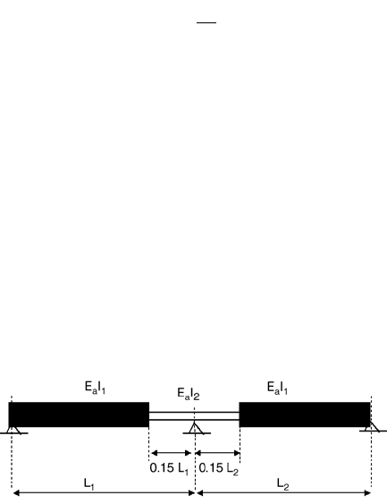
Hogging moments and top-fiber concrete stresses, s
ct
, are determined at each internal support using
the flexural stiffnesses E
a
I
1
. For each support at which s
ct
exceeds 0.15f
ck
, the stiffness should be reduced
to the value E
a
I
2
over 15% of the length of the span on each side of the support. A new distribution of
bending moments is then determined by reanalyzing the beam. At every support where stiffnesses E
a
I
2
are used for a particular loading they should be used for all other loadings, as shown in Fig. 51.31.
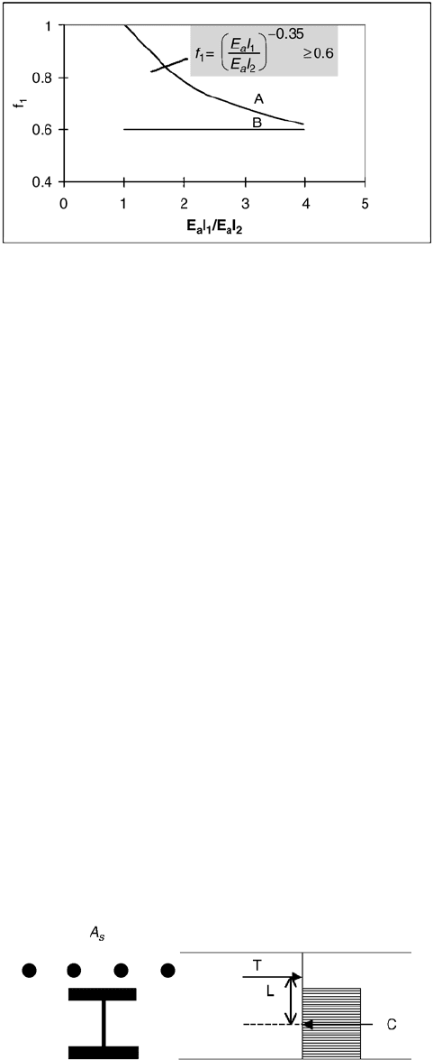
For beams with classes 1–3, where s
ct
exceeds 0.15f
ck
, the bending moment at the support is multiplied
by a reduction factor f
1
and corresponding increases are made to the bending moments in adjacent spans,
as shown in Fig. 51.32. Curve A should be used when loading on all spans is equal and the lengths of all
FIGURE 51.31 Distribution of flexural rigidities for a continuous composite beam.
n
E
E
a
c
=
¢
© 2003 by CRC Press LLC
Composite Steel–Concrete Structures 51-29
spans do not differ by more than 25%. Otherwise, the approximate lower bound f
1
= 0.60 should be
used (i.e., line B).
In unpropped beams account may be taken of the influence of local yielding over a support by
multiplying the bending moments at the support by:
•f
2
= 0.5 if f
y
is reached before the concrete slab has hardened.
•f
2
= 0.7 if f
y
is caused by the loading after the concrete has hardened.
Cracking
Some important points to note about cracking in EC4, which are covered in Section 5.3, include: design
crack widths should be agreed with the client; minimum reinforcement requirements are specified;
maximum steel stresses are specified for bar sizes and required crackwidths; and elastic global analysis
is used to ascertain internal forces and moments.
Strength
In the hogging moment region, the moment resistance of the composite beam section depends on the
tensile resistance of the steel reinforcement and the compression resistance of the steel beam section.
Partial shear connection also exists; however, it depends on the steel reinforcement strength in tension,
rather than the concrete slab in compression. The moment resistance depends on the location of the
plastic neutral axis as follows.
Plastic Neutral Axis in the Concrete Slab (Full Shear Connection, = 1.0)
When the steel reinforcing is stronger than the steel beam, the plastic neutral axis will lie within the
concrete slab. For the case when the plastic neutral axis lies within the concrete slab, the ultimate flexural
strength is determined from a simple couple, as shown in Fig. 51.33.
M
u
= TL = CL (51.38)
FIGURE 51.32 Reduction factor for bending moment at supports.
FIGURE 51.33 Ultimate flexural moment, plastic neutral axis in concrete slab (b = 1.0).
© 2003 by CRC Press LLC