Wai-Fah Chen.The Civil Engineering Handbook
Подождите немного. Документ загружается.

56-8 The Civil Engineering Handbook, Second Edition
This equation is valid only if the two vectors are expressed in the same coordinate system. The image
space vector is inevitably expressed in an image coordinate system:
Æ
a = (56.13)
while the object space vector is expressed in an object space coordinate system (shifted to the camera
perspective center):
Æ
A = (56.14)
One thus needs to scale, rotate, and translate one of these two coordinate systems until they are
coincident. This transformation is usually applied to the object space vector and is expressed as follows:
(56.15)
Eliminating the scale parameter k yields the classical form of the collinearity equations:
(56.16)
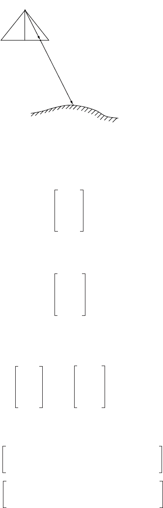
Examples of particular problems for which the collinearity equations are useful include space resection
(camera exterior orientation unknown, object points known, observed image coordinates given, usually
implying a single image), space intersection (camera exterior orientations known, object point unknown,
observed image coordinates given, usually implying a single object point), and bundle block adjustment
(simultaneous resection and intersection, multiple images, and multiple points). This equation is non-
linear and a linear approximation is usually made if we attempt to solve for any of the variables as
unknowns. This dictates an iterative solution.
FIGURE 56.8 Collinearity geometry.
L
a
A
→
a = La
Image Space
Vector
→
A = LA
Object Space
Vector
xx
0
–
yy
0
–
f–
XX
L
–
YY
L
–
ZZ
L
–
xx
0
–
yy
0
–
f–
kM
XX
L
–
YY
L
–
ZZ
L
–
=
xx
0
– f
m
11
XX
L
–()m
12
YY
L
–()m
13
ZZ
L
–()++
m
31
XX
L
–()m
32
YY
L
–()m
33
ZZ
L
–()++
---------------------------------------------------------------------------------------------------
–=
yy
0
– f
m
21
XX
L
–()m
22
YY
L
–()m
33
ZZ
L
–()++
m
31
XX
L
–()m
32
YY
L
–()m
33
ZZ
L
–()++
---------------------------------------------------------------------------------------------------
–=
© 2003 by CRC Press LLC
Photogrammetry and Remote Sensing 56-9
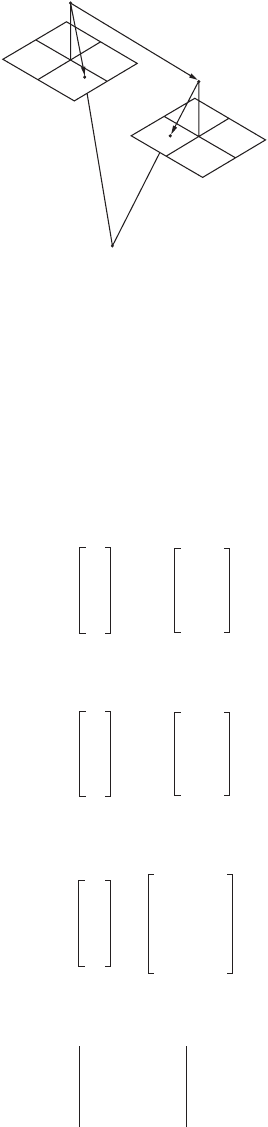
Coplanarity Equation
The phrase conjugate image points refers to multiple image instances of the same object point. If we
consider a pair of properly oriented images and the pair of rays defined by two conjugate image points,
then this pair of rays together with the base vector between the perspective centers should define a plane
in space. The coplanarity condition enforces this geometrical configuration. This is done by forcing these
three vectors to be coplanar, which is in turn guaranteed by setting the triple scalar product to zero. An
alternative explanation is that the parallelepiped defined by the three vectors as edges has zero volume.
Figure 56.9 illustrates this geometry. The left vector is given by
(56.17)
The right vector is given by
(56.18)
and the base vector is given by
(56.19)
The coplanarity condition equation is the above-stated triple scalar product
(56.20)
The most prominent application for which the coplanarity equation is used is relative orientation.
The equation is nonlinear and a linear approximation is usually made in order to solve for any of the
variables as unknowns. This dictates an iterative solution.
FIGURE 56.9 Coplanarity geometry.
b
→
a
→
2
a
→
1
a
1
u
1
v
1
w
1
M
1
t
xx
0
–
yy
0
–
f–
1
==
a
2
u
2
v
2
w
2
M
2
t
xx
0
–
yy
0
–
f–
2
==
b
b
x
b
y
b
z
X
L
2
X
L
1
–
Y
L
2
Y
L
1
–
Z
L
2
Z
L
1
–
==
F
b
x
b
y
b
z
u
1
v
1
w
1
u
2
v
2
w
2
0==
© 2003 by CRC Press LLC
56-10 The Civil Engineering Handbook, Second Edition
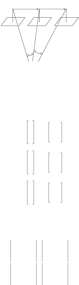
Scale Restraint Equation
If photograph one is relatively oriented to photograph two, and photograph two is relatively oriented to
photograph three, there is no guarantee that photograph one and photograph three are also relatively
oriented. There are several methods to enforce this condition, and among them the most robust would
be the scale restraint condition. This states that the intersection of conjugate rays from the three photo-
graphs should in fact occur at a single point. From Fig. 56.10 we see the three rays, a
i
, and two “mismatch”
vectors, d
i
:
(56.21)
(56.22)
(56.23)
(56.24)
(56.25)
The scale restraint equation itself forces the independent scale factors for the common ray to be equal:
(56.26)
FIGURE 56.10 Scale restraint geometry.
L
1
(M
1
)L
2
(M
2
)L
3
(M
3
)
→
b
1
→
d
2
→
d
1
→
b
2
→
a
3
→
a
2
→
a
1
a
1
a
1
x
a
1
y
a
1
z
M
1
t
x
1
x
0
–
y
1
y
0
–
f–
==
a
2
a
2
x
a
2
y
a
2
z
M
2
t
x
2
x
0
–
y
2
y
0
–
f–
==
a
3
a
3
x
a
3
y
a
3
z
M
3
t
x
3
x
0
–
y
3
y
0
–
f–
==
d
1
a
1
a
2
¥=
d
2
a
2
a
3
¥=
F
a
1
x
d
1
x
b
1
x
a
1
y
d
1
y
b
1
y
a
1
z
d
1
z
b
1
z
a
1
x
d
1
x
a
2
x
a
1
y
d
1
y
a
2
y
a
1
z
d
1
z
a
2
z
------------------------------------
b
2
x
d
2
x
a
3
x
b
2
y
d
2
y
a
3
y
b
2
z
d
2
z
a
3
z
a
2
x
d
2
x
a
3
x
a
2
y
d
2
y
a
3
y
a
2
z
d
2
z
a
3
z
------------------------------------+ 0==
© 2003 by CRC Press LLC
Photogrammetry and Remote Sensing 56-11
This equation is used primarily in the analytical formation of strips by successive relative orientation
of image pairs in the strip. Common points in any photo triplet (that is, two adjacent models) would be
subjected to the scale restraint condition. This equation is nonlinear and would require linear approxi-
mation for practical use in the given application.
Linear Feature Equations
It can happen, particularly in close-range photogrammetry, that the object space parameters of a straight
line feature are to be determined. If at the same time stereo observation is either unavailable or difficult
because of convergence or scale, then it becomes helpful if one can observe the feature monoscopically
on each image without the need for conjugate image points. This can be elegantly accomplished with a
condition equation which forces the ray associated with an observed image coordinate to pass through
a straight line in object space. For each point in each photograph, a condition equation of the following
kind may be written:
(56.27)
In this equation the vector r is the object space vector from the observed image point, the vector b is
the vector along the straight line in object space, and LC is the vector from the perspective center to the
point on the line closest to the origin. The six linear feature parameters must be augmented by two
constraints which fix the magnitude of b to 1, and guarantee that b and C are orthogonal. A variation
on this technique is the case where the object space feature is a circle in space. In this case each point
on each image contributes an equation of the form
(56.28)
where r and L have the same meaning as before. h represents the normal vector to the circle plane, r
represents the circle radius, and C represents the circle center. In this case the normal vector must be
constrained to unit magnitude. As in every case described here these equations are nonlinear in the variables
of interest, and when we solve for them, the equations must be approximated using the Taylor series.
Block Adjustment
The internal geometry of a block of overlapping photographs or images may be sufficient to determine
relative point positions, but for topographic mapping and feature extraction, one needs to tie this block
to a terrestrial coordinate system. It would be possible to provide field survey determined coordinates
for every point, but this would be prohibitively expensive. Thus arises the need to simultaneously tie all
the photographs to each other, as well as to a sparse network of terrestrial control points. This process
is referred to as block adjustment. The minimum amount of control necessary would be seven coordinate
components, i.e., two horizontal (X, Y ) points and three vertical (Z) points, or two complete control
points (X, Y, Z) and one point with only vertical (Z). In practice, of course, one usually provides control
in excess of the minimum, the redundancy providing increased confidence in the results.
Block Adjustment by Bundles
Block adjustment by bundles is the most mathematically rigorous way to perform this task. Observations
consist of 2-D photograph image coordinates, usually read from a comparator or analytical plotter,
transformed to the principal point origin, and refined for all known systematic errors. These systematic
errors, described below, consist of at least lens distortion and atmospheric refraction, although at low
altitude refraction may be considered negligible. Each image point, i, on each image, j, contributes two
collinearity condition equations of the form
r
x
r
y
r
z
b
x
b
y
b
z
LC
x
LC
y
LC
z
0=
LC–()
LC–()
h
rh
---------------------
r
– r=
© 2003 by CRC Press LLC
56-12 The Civil Engineering Handbook, Second Edition
(56.29)
in which (x
i
, y
i
) are the observed image coordinates, transformed into a coordinate system defined by
the camera fiducial coordinates. The variables (x
0
, y
0
) represent the position of the principal point and
f represents the focal length or principal distance. The last three variables would often be considered as
fixed constants from a camera calibration report, or they may be carried as unknowns in the adjustment.
The variables (X
i
, Y
i
, Z
i
) represent the object coordinates of the point i. They may be known or partially
known if point i is a control point, or they may be unknown if point i is a pass point. The variables
(X
L
j
, Y
L
j
, Z
L
j
) represent the coordinates of the exposure station or perspective center of image j. Each
image, j, also has an associated orientation matrix, M
j
, whose elements are shown in the equation. If
there are n points observed on m images, the total number of condition equations will be 2n
m. The total
number of unknowns will be 3n + 6m – (number of fixed coordinate components). With the advent of
GPS in the photo aircraft, control may be introduced not only at the object points but also at the exposure
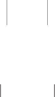
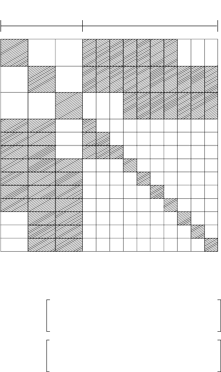
stations. If the solution to the overdetermined problem is carried out by normal equations, the form of
these equations is shown in Fig. 56.11.
Block Adjustment by Models
Block adjustment by models is necessary if the original observations of the photographs are made in stereo
with an observed (x, y, z) model coordinate for each control point and pass point. Together with the model
coordinates of the perspective centers, all model points are simultaneously transformed to the object (or
control) coordinate system. There is usually redundant information to specify this transformation, so a
FIGURE 56.11 Organization of normal equations for bundle adjustment.
Photograph
Parameters
Object Point
Parameters
x
i
x
0
– f
m
11
X
i
X
L
j
–()m
12
Y
i
Y
L
j
–()m
13
Z
i
Z
L
j
–()++
m
31
X
i
X
L
j
–()m
32
Y
i
Y
L
j
–()m
33
Z
i
Z
L
j
–()++
----------------------------------------------------------------------------------------------------------
–=
y
i
y
0
– f
m
21
X
i
X
L
j
–()m
22
Y
i
Y
L
j
–()m
33
Z
i
Z
L
j
–()++
m
31
X
i
X
L
j
–()m
32
Y
i
Y
L
j
–()m
33
Z
i
Z
L
j
–()++
----------------------------------------------------------------------------------------------------------
–=
© 2003 by CRC Press LLC
Photogrammetry and Remote Sensing 56-13
least squares estimation is necessary. Practitioners have used comparator-derived image coordinates to
compute model coordinates, and then subjected these derived model coordinates to an independent
model block adjustment. This practice should be discouraged in favor of using the image coordinates
directly in a bundle adjustment as described above. For the independent model block adjustment, each
point, i, in model (stereo pair), j, will be related to the object space coordinates by a seven-parameter
transformation unique to each model. The seven parameters include scale, s, rotations, W
, F, and K, and
translations T
x
, T
y
, T
z
. For each point, i, in each model, j, the following three equations can be written:
(56.30)
The uppercase coordinate vector represents the coordinate system of the control points, the lowercase
vector represents the model coordinates, and the matrix M contains the rotation parameters. Only for
control points will the (X, Y, Z) values be known; for all other points these will be unknown parameters
solved for in the block adjustment. For n points and m models the total number of condition equations
would be 3n
m. The total number of unknown parameters would be 3n + 7m – (number of fixed
coordinate components).
Strip Formation and Block Adjustment by Polynomials
Strip formation and block adjustment by polynomials assumes that the input data are x
y z model coor-
dinates. These would usually come directly from a relatively oriented model in an analogue stereoplotter.
They could also come from analytical computation from image coordinates. If this is the case it would be
preferable to use the image coordinates directly in a bundle block adjustment. A similar comment was
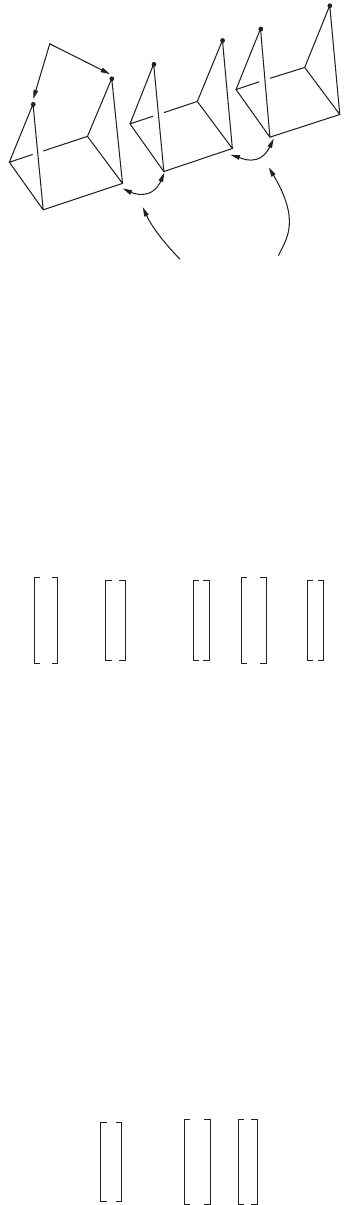
made with regard to the independent model block adjustment. The strip formation consists of linking
successive models (including perspective center coordinates) by seven-parameter transformations, and
then transforming each new model into the strip system based on the first model. This process is illustrated
in Fig. 56.12. If a single strip is sufficiently short, say five models or less, the strip can be fitted to the
control points by a global seven-parameter transformation. This is given in the following equation:
(56.31)
FIGURE 56.12 Model connection and strip formation.
Model 3-4
Model 2-3
Model 1-2
model connection by
3 Dimensional Coordinate
Transformation
Perspective
Centers
F
1
F
2
F
3
X
Y
Z
i
– s
j
M
j
x
y
z
i
T
x
T
y
T
z
j
++
0
0
0
==
E
N
h
sM
x
m
y
m
z
m
t
x
t
y
t
z
+=
© 2003 by CRC Press LLC
56-14 The Civil Engineering Handbook, Second Edition
If the strip is longer than this, then because of adverse error propagation, artificial bends and bows
will be present in the strip coordinates and polynomials present a way to model such effects. This
technique is primarily of historical interest since its computational efficiency is no longer a compelling
attribute. Both model coordinates and ground coordinates are transformed into an “axis of flight”
coordinate system centered within the strip. Then conformal polynomials are used to transform the strip
planimetric coordinates into the control system:
(56.32)
(56.33)
The vertical control points are used in the following polynomial:
(56.34)
The number of terms is selected based on the quantity of control points and the length of the strip.
Following the polynomial estimation, the points are transformed back into the original control coordinate
system.
Image Coordinate Refinement
Raw stage coordinates from a comparator or analytical plotter must undergo a number of transformations
and refinements before being used in further photogrammetric processing such as relative orientation or
bundle block adjustment. Firstly the stage coordinates are transformed into the coordinate system defined
by the camera fiducial marks or registration marks. This is usually done with a four- or six-parameter
transformation. They are then shifted to the principal point of autocollimation by the principal point offsets
(x
0
, y
0
). Following this they are corrected for radial lens distortion based on their position with respect to
the principal point of best symmetry. The radial lens distortion is provided as part of the calibration of the
camera either in the form of a table, a graph, or a polynomial function. A sample radial lens distortion
graph is shown in Fig. 56.5. The usual form for polynomial lens distortion functions is given by
(56.35)
in which the radial distance r is the distance from the symmetry point mentioned above. If a distortion
table or function is given, the correction should be applied with the opposite sign. Conventionally, “+”
indicates radial distortion outward from the principal point. Thus the correction equations would be
(56.36)
Following lens distortion correction the image coordinates should be corrected for atmospheric refrac-
tion (if it is significant, i.e., on the order of a micrometer or larger). The expression for radial image
displacement due to atmospheric refraction is given by
(56.37)
where r is the radial distance from the principal point of autocollimation and f is the focal length. The
value for K is a function of the camera altitude and terrain elevation, and is given according to the ARDC
Model Atmosphere (Air Research and Development Command of the U.S. Air Force):
x ¢ xa
1
a
3
xa
4
y– a
5
x
2
y
2
–()2a
6
xy– a
7
x
3
3xy
2
–()a
8
3x
2
yy
2
–()– L++ + + +=
y ¢ ya
2
a
4
xa
3
ya
6
x
2
y
2
–()2a
5
xy a
7
3x
2
yy
3
–()a
8
x
3
3x
2
y–()L++ + + + + + +=
z
¢
zb
0
2b
2
x– 2b
1
yc
1
x
2
c
2
x
3
c
3
x
4
d
1
xy d
2
x
y
d
3
x
3
yd
4
x
4
ye
1
y
2
e
2
xy
2
+++++
++++++
=
rD k
0
rk
1
r
3
k
2
r
5
k
3
r
7
+++=
x
c
x 1
rD
r
-----–
˯
ʈ
=
y
c
y 1
rD
r
-----–
˯
ʈ
=
d
r
Kr
r
3
f
2
----+
˯
ʈ
=
© 2003 by CRC Press LLC
Photogrammetry and Remote Sensing 56-15
(56.38)
where H is the flying height in kilometers above sea level and h is the terrain height, also in kilometers
above sea level. The displacement due to atmospheric refraction is always radially outward, therefore the
correction is always radially inward. The same correction formulas may be used as in the case of lens
distortion, replacing Dr by dr. Some practitioners have advocated handling earth curvature effects by
modifying the image coordinates. This is to be discouraged. A better solution is to ensure that the object
space coordinate system is truly Cartesian, and then the “problem” disappears. See the following section
for a discussion of this.
Object Space Coordinate Systems
Geodetic Coordinates , , h
Geodetic coordinates, that is, latitude, longitude, and height, are the most fundamental way to represent
the position of a point in space with respect to a terrestrial ellipsoid. However, photogrammetric condition
equations are usually expressed in terms of rectangular, Cartesian coordinates. Thus, for the purpose of
providing a reference frame for photogrammetric computations, one would usually transform f, l, and
h into a rectangular system.
Space Rectangular Coordinates
Geocentric space rectangular coordinates may be derived from geodetic coordinates in such a way that
the Z axis is parallel with the axis of rotation of the ellipsoid, and the X axis passes through the meridian
of Greenwich in the plane of the equator. The Y axis is constructed so that the system is right-handed.
In the following, h is assumed to be the ellipsoid height; if geoid height is given, it must be modified by
the local geoid separation. The equations transforming geodetic coordinates into geocentric space rect-
angular coordinates are given by
(56.39)
where N, the radius of curvature in the prime vertical is given by
(56.40)
where a = the semimajor axis of the ellipsoid
b = the semiminor axis
e = the eccentricity given by
(56.41)
The inverse transformation cannot be given in a closed form. One can solve for f, l, and h by choosing
an initial approximation and proceeding iteratively by the conventional Newton method,
(56.42)
or
K
2410H
H
2
6H– 250+
-----------------------------------
2410h
h
2
6h– 250+
--------------------------------
h
H
----
˯
ʈ
–
10
6–
¥=
XNh+()
fl
coscos=
YNh+()
fl
sincos=
ZN1 e
2
–()h+[]
f
sin=
N
a
1 e
2
sin
2
f
–
-------------------------------=
e
a
2
b
2
–()
a
2
--------------------=
X
i 1+
X
i
J
1–
FX
i
()–=
© 2003 by CRC Press LLC
56-16 The Civil Engineering Handbook, Second Edition
(56.43)
and the three functions are the ones given in Eq. (56.39). One possible difficulty with the use of geocentric
space rectangular coordinates is the large magnitude of the coordinate values. If one wished to maintain
point precision to the nearest millimeter, 10 significant digits would have to be carried in the coordinates
and single precision floating point computations would be insufficient. An alternative is the local space
rectangular system, which is just the geocentric space rectangular coordinates, rotated so that Z
¢ passes
through a local point, Y
¢ is in the meridian plane, and X ¢ is constructed for a right-handed system. The
LSR, or local space rectangular coordinates, are given by
(56.44)
where GSR refers to the geocentric space rectangular coordinate vector, the T vector is the translation to
the local origin, and the rotation matrix M is given by
(56.45)
Map Projections Coordinates
The common map projections used to express terrestrial control points are the lambert conformal conic
and the transverse mercator. In the U.S., each state has a state plane coordinate system utilizing possibly
multiple zones of these projections. Globally, there is the UTM, or universal transverse mercator system, in
which the globe is divided into 60 zones of width 6 degrees. Zone 1 is from 180 degrees west to 174 degrees
west, and the zone numbering proceeds eastward until the globe is covered at zone 60. The zones are limited
to ± 80 degrees latitude, and the scale factor at the central meridian is 0.9996. All of the above map projection
coordinates have a common deficiency when used in photogrammetry. The XY coordinate is with respect
to the developed projection surface, but the height coordinate is usually with respect to a sea level datum.
Thus the system is not Cartesian. Over a very small region one could neglect the curved Z-reference, but
over any substantial project area the nonorthogonality of the coordinate system will present itself in pho-
togrammetric computations as a so-called earth curvature effect. The best approach to handling this
situation is to either transform all control points into an LSR system described above or construct a local
tangent plane system from the map projection coordinates, modifying the height component as follows:
(56.46)
where the subscript t
p refers to the tangent plane system, sl refers to the sea level system, D is the distance
from a project centered tangent point, and R is the nominal earth radius. Following all photogrammetric
computations, that is, block adjustment, the heights can be corrected back into the sea level system for
use by compilers and engineers.
f
i 1+
l
i 1+
h
i 1+
f
i
l
i
h
i
F
1
∂
f∂
--------
F
1
∂
l∂
--------
F
1
∂
h
∂
--------
F
2
∂
f∂
--------
F
2
∂
l∂
--------
F
2
∂
h
∂
--------
F
3
∂
f∂
--------
F
3
∂
l∂
--------
F
3
∂
h
∂
--------
1–
F
1
f
i
l
i
h
i
,,()
F
2
f
i
l
i
h
i
,,()
F
3
f
i
l
i
h
i
,,()
–=
X
¢
Y
¢
Z
¢
LSR
M
X
Y
Z
GSR
T
X
T
Y
T
Z
–
=
M
l
sin–
l
cos 0
F
l
cossin– F
l
sinsin– Fcos
F
l
coscos F
l
sincos Fsin
=
h
tp
h
sl
D
2
2
------
R–=
© 2003 by CRC Press LLC

Photogrammetry and Remote Sensing 56-17
56.4 Instruments and Equipment
Stereoscopes
Stereo viewing is possible with the unaided eyes if conjugate imagery is placed at a spacing approximately
equal to the eye base, at a comfortable distance in front of the eyes. Prolonged viewing at such a distance
may produce eye fatigue and therein lies the value of a stereoscope. A simple lens stereoscope allows the
eyes to focus comfortably at infinity, thus permitting longer working sessions. For frame photographs,
the overlapping pair should be laid out with the flight lines coincident and the spacing adjusted for
comfortable viewing. Only a small portion of a standard 23-cm photograph overlap area can be viewed
in this way, and some bending of the paper prints may be necessary to access the full model area. A
mirror stereoscope, being larger, permits viewing of almost an entire overlap area, at a necessarily smaller
scale. Approximate elevations can be read via a parallax bar and the associated 3-D measuring mark.
Some modern softcopy stereo viewing systems employ nothing more than a simple mirror stereoscope
to view conjugate imagery presented in split-screen mode on a video monitor.
Monocomparator, Stereocomparator, Point Marker
Both of the comparator instruments have been largely superseded by the analytical plotter, which is really
nothing more than a computer-controlled stereocomparator. In any case, a monocomparator is a single
two-axis stage with a measuring microscope and a coordinate readout, preferably with an accuracy of
1 or 2 micrometers. A stereocomparator is a pair of two-axis stages which permit stereo viewing by a
pair of measuring microscopes, and simultaneous coordinate readout of two pairs of ( XY ) coordinates.
Accuracy levels should be comparable to that mentioned for the monocomparator. Both of these com-
parator instruments are used chiefly for aerial triangulation, bridging, or control extension. In this process,
all control points and pass points are read for all photographs in a strip or block. The photos are then
linked by geometric condition equations and tied to the ground coordinate system, thus producing
ground coordinates for all observed pass points. These pass points may then be used for individual model
setups in a stereo restitution instrument. If pass points are desired in an area of the photograph without
identifiable detail points, artificial emulsion marks or “pug points” are introduced by a point marker or
“pug.” These marks are typically 40- to 80-micrometer-diameter drill holes in the photograph emulsion,
sized to be compatible with the stereo measuring device.
Stereo Restitution: Analogue, Analytical, Softcopy
Early instruments for map compilation consisted of optical projectors and a small viewing screen with
a means to direct the image from one projector to the left eye and from the other projector to the right
eye. This binocular separation was effected by anaglyph (red and blue filters), by mechanical shutter, and
by polarization. Analogue instruments in use today employ exclusively mechanical projection in which
a collection of gimbals, space rods, and cardan joints emulate the optical light paths. All analogue
instruments must provide a way to re-create the inner camera geometry by positioning the principal
point (via the fiducial marks) and setting the principal distance or focal length. These steps constitute
the interior orientation. A procedure is also necessary to reestablish the relative orientation of the pho-
tographs at instant of exposure. This is accomplished by clearing y-parallax, or y displacement in model
space between the projected images, in at least five points spaced throughout the model. For the point
layout in Fig. 56.13 the sequence of steps for two-projector relative orientation is as follows:
1. Clear at point 1 with kappa-right.
2. Clear at point 2 with kappa-left.
3. Clear at point 3 with phi-right.
4. Clear at point 4 with phi-left.
5. Clear at point 5 with omega-left or omega-right.
6. Check for no parallax at point 6.
© 2003 by CRC Press LLC