Wai-Fah Chen.The Civil Engineering Handbook
Подождите немного. Документ загружается.

Airport Planning and Design 59-51
for generating noise as a function of trip length (takeoff weight and flap setting) and flap setting on
landing. Figure 59.32 shows a typical output of the program in terms of L
DN
.
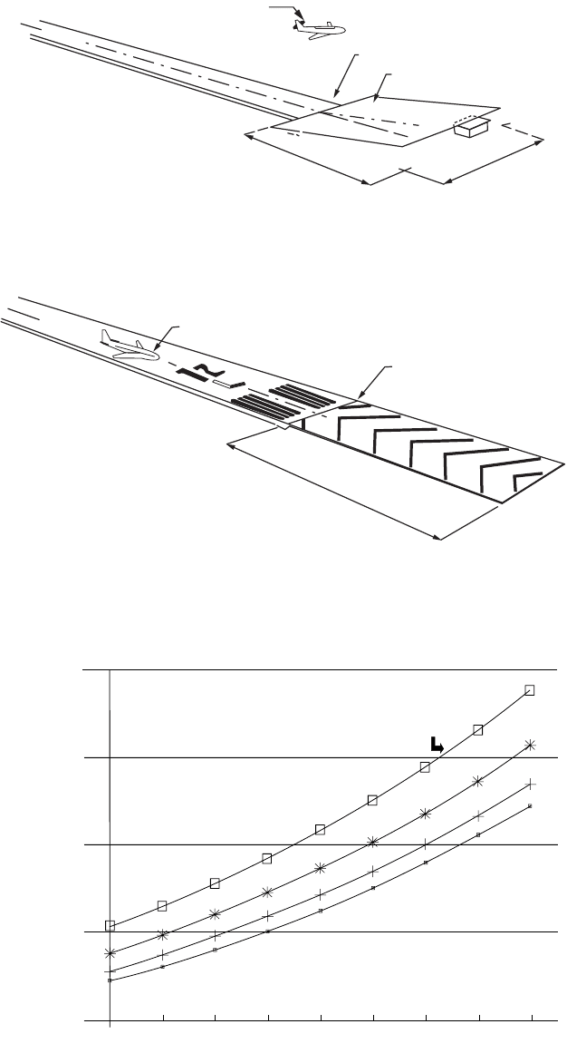
To identify the places of noise impact the contours are overlaid on a map of the community.
Figure 59.33 shows the impact on the community for the Standiford Airport in Louisville, Kentucky. The
takeoff and landing tracks are critical and can have a large impact on the community noise patterns. The
data appearing in the inset of Fig. 59.33 indicate the level of community impact.
The noise models using either L
DN
or NEF are essential for airport authorities in planning and working
with communities. For simple planning, an area about 2 miles wide and 6 miles from the end of the
runway should provide a quick, hopefully conservative, view of potential noise problems.
59.8 Airside Layout and Design
Design begins with the knowledge of both the performance and physical characteristics of the aircraft
that will use the airport. As defined in Section 59.5, the approach or landing speed defines an aircraft
category as A, B, C, or D. The designation of aircraft size is based on grouping aircraft according to the
length of their wingspan, called aircraft design group (ADG), as follows:
Group I: up to but not including 49 ft (15 meters)
Group II: 49 ft (15 m) up to but not including 79 ft (24 m)
TABLE 59.26 Capabilities of INM
Measure of Noise Symbol Description
Noise exposure forecast NEF Based on EPNL as a unit of aircraft noise; nighttime
operations are weighted by 16.7 per one operation
Equivalent sound level SEL Summation of aggregate noise environment dBA
Day–night average sound L
DN
Based on SEL with nighttime operations weighted by a
10-dB penalty; see Eq. (59.13)
Time above threshold of
A-weighted sound
TA Time in min that a dBA level is exceeded in a 24-h period
Source: FAA, Integrated Noise Model, Version 3, revision 1, DOT/FAA/EE-92/02, 1992.
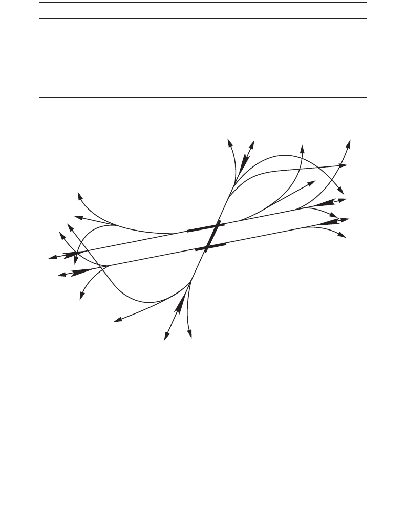
FIGURE 59.31 Input flight tracks to the integrated noise model.
TR21
TR22
TR31
TR25
TR20
TR24
TR28
TR23
TR27
TR26
TR32
TR31
TR30
TR33
TR2
TR1
TR10
TR3
TR4
TR9
TR7
TR15
TR16
TR6
TR8
TR19
TR18
TR17
© 2003 by CRC Press LLC
59-52 The Civil Engineering Handbook, Second Edition
FIGURE 59.32 Noise contours for planning purposes.
FIGURE 59.33 Sample of noise contours and community land-use plan. (From FAA, Final Environmental Impact
Statement, Standiford Field Airport, Louisville, KY, 1990.)
(-36000,24000) (36000,24000)
ANNUAL AVERAGE EXPOSURE AT AN EXAMPLE OF A MEDIUM HUB AIRPORT
EXAMPLE MHA
METRIC = LDN 65.0 75.0
AREA (SQ MI) = 16.9 4.2 8000 ft
++++ ++++
+ ++++
75 dB
65 dB
© 2003 by CRC Press LLC
Airport Planning and Design 59-53
Group III: 79 ft (24 m) up to but not including 118 ft (36 m)
Group IV: 118 ft (36 m) up to but not including 171 ft (52 m)
Group V: 171 ft (52 m) up to but not including 214 ft (65 m)
Group VI: 214 ft (65 m) up to but not including 262 ft (80 m)
The important physical characteristics of the aircraft affecting airport design are maximum takeoff
weight (W), wingspan (A), length (B), tail height (C), wheel base (D), nose to centerline of main gear
(E), undercarriage width (1.15 ¥ main gear track, F), and line-of-sight/obstacle-free zone at the nose of
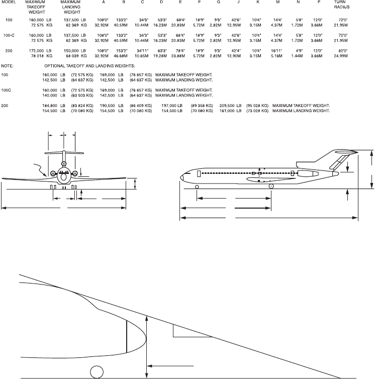
the aircraft. For reference, these are presented for the Boeing 727 in Fig. 59.34 [FAA, 1991c].
Figure 59.35 displays a major problem faced by aircraft as they land and travel on the runway, taxiway,
or taxilane system. The pilot’s view of the ground directly in front of the aircraft is obscured by the nose.
This blind zone for the pilot is known as the object-free zone (OFZ) and is important for safe ground
movement of aircraft. It affects the geometric design of the runway and taxiway. Table 59.27 shows the
approach speed and physical characteristics for several specific aircraft.
Other input data to the computer program are the primary navigation capability, the altitude or
elevation of the airport, and the mean temperature of the hottest month of the year. The program outputs
FIGURE 59.34 Sample aircraft dimensions (Boeing 727) for airport design. (From FAA, Airport Design, Advisory
Circular AC150/5300-13, change 1, 1991c.)
FIGURE 59.35 Object-free zone requirements as viewed from the cockpit. (From FAA, Airport Design, Advisory
Circular AC150/5300-13, change 1, 1991c.)
D
E
B
P
C
M
G
K
F
J
N
A
PIVOT
POINT
(APPROX.)
OFZ
1
3
Height of OFZ
at nose of airplane
© 2003 by CRC Press LLC

59-54 The Civil Engineering Handbook, Second Edition
include runway lengths, widths, and clearance standards. Outputs that develop taxiway design data, such
as widths and clearance standards, steering angles on tangent sections, circular curve layouts, spiral curve
layouts, offset distances on taxiway intersections, offsets on exit taxiways, and the wing tip clearance on
taxiways, are possible. The program has plotting capability for exit taxiways, taxiway intersections, or the
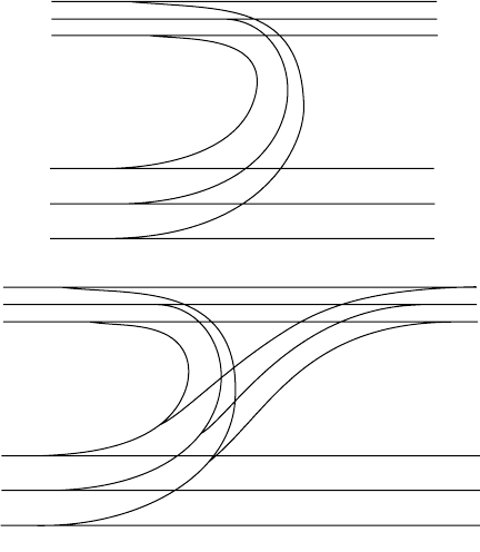
curved track for wing tip clearance on taxiways, as demonstrated in the spiral-double-back exit taxiway
and acute-angled taxiway plotted in Fig. 59.36. The design program will also calculate the wind rose data.
(See Section 59.7.)
Runway Length
The length of the runway is determined by the aircraft, maximum takeoff weights, engine capabilities,
landing and braking capabilities, flap settings, and required safety factors. For example, the runway length
for landing must be capable of permitting safe braking if touchdown occurs one third the length of the
runway past the threshold. The runway must also be long enough to meet the obstacle-free capability to
permit each aircraft to take off with one engine out. The stopping zone must include ample stopping
distance in case the pilot chooses to abort takeoff just before rotating to become airborne (called stopway).
As discussed, the runway safety areas are a must for airport control. Figure 59.37 shows the stopway, to
prevent accidents at the end of the runway, and the clearway, also called the runway protection zone.
The altitude of the airport and the temperature also have a significant impact on the airport runway
length, because lift capability is proportional to the air density, which diminishes as the altitude and
temperature increase. Figure 59.38 illustrates how dramatic that change is for a Boeing 727-200 with a
JT8D-15 engine, a takeoff weight of 150,000 pounds, and its wing flaps set at 20 degrees. The requirement
for longer runways increases significantly as the altitude of the site above sea level increases. At an average
temperature of 65 degrees Fahrenheit, the increase is from 4900 feet at sea level to 8660 feet at an altitude
of 8000 feet, or about 370 feet of added runway for each 1000-foot increase in altitude. The increase due
to temperature, especially when the temperature is high, is equally dramatic. Going from 65 to 80 degrees
Fahrenheit for an airport at a 4000-foot elevation requires an increase in runway length of about 24 feet
per degree Fahrenheit. For the shift from 95 to 110 degrees Fahrenheit for an airport at a 4000-foot
TABLE 59.27 Aircraft Data Used by Design Program (Representative Sample)
Aircraft Make/Model
Airport
Reference
Code
Approximate
Approach Speed
(knots)
Wingspan
(ft)
Length
(ft)
Tail
Height
(ft)
Maximum
Ta ke of f
We ight (lb)
Cessna-150 A-I 55 32.7 23.8 8.0 1,600
Beech King Air-B100 B-I 111 45.8 39.9 15.3 11,800
Gates Learjet 54-56 C-I 128 43.7 55.1 14.7 21,500
Dornier LTA A-II 74 58.4 54.4 18.2 15,100
Shorts 360 B-II 104 74.8 70.8 23.7 26,453
Grumman Gulfstream III C-II 136 77.8 83.1 24.4 68,700
DHC-8, Dash 8-300 A-III 90 90 84.3 24.6 41,100
Fairchild F-27 B-III 109 95.2 77.2 27.5 42,000
Boeing 727–200 C-III 138 108 153.2 34.9 209,500
Boeing 737-400 C-III 138 94.8 119.6 36.6 150,000
MDC-DC-9-50 C-III 132 93.3 133.6 28.8 121,000
Airbus 300-600 C-IV 135 147.1 177.5 54.7 363,763
Boeing 757 C-IV 135 124.8 155.3 45.1 255,000
Boeing 767-300 C-IV 130 156.1 180.3 52.6 350,000
MDC-DC-8-50 C-IV 133 142.4 150.8 43.3 325,000
MDC-DC-10-30 D-IV 151 165.3 181.6 58.6 590,000
MDC-MD-11 D-IV 155 169.8 201.3 57.8 602,500
Boeing 747-200 D-V 152 195.7 231.8 64.7 833,000
Boeing 747-400 D-V 154 213.0 231.8 64.3 870,000
Lockheed C5A C-VI 135 222.7 247.8 65.1 837,000
Source: FAA, Airport Design, Circular AC150/5300-13, change 1, 1991c.
© 2003 by CRC Press LLC
Airport Planning and Design 59-55
elevation the rate of increase in runway length is 58 feet per degree Fahrenheit. Thus on any specific
runway there is a maximum allowable takeoff weight (MATOW), depending on the ambient temperature,
the specific aircraft (with its specific engines), and the altitude of the airport.
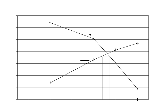
The advisory circular [FAA, 1990a] on runway length presents the takeoff weight data for several
different flap angles. Taking off with a low flap angle permits a higher MATOW, but takes a longer runway
to attain the speed to become airborne. Figure 59.39 plots the MATOW for various flap angles for a
temperature of 90 degrees Fahrenheit at the TBA airport. The curve beginning at the lower left is
constrained by the length of the 9500-foot (2900-meter) runway, while the curve beginning at the upper
left is constrained only due to aircraft engine thrust capability of the JT8D-15 engines, assuming sufficient
runway length is available. A setting of flap angle at about 17 degrees will give the highest MATOW of
167,500 lb (76,050 kg) for a day with a 90-degree-Fahrenheit temperature.
The major operational constraint, when there is a weight limitation caused by a shorter-than-optimum
runway, is the range that can be achieved. The 727-200 with JT8D-15 engines has an empty weight of
109,211 lb and a structural payload weight of 40,339 pounds [FAA, 1990a]. Tables such as the example
shown in Table 59.28 are available for most aircraft and for a range of flap angle settings for each aircraft.
If the flaps are set at 15 degrees at the MRA airport on a 90-degree-Fahrenheit day, it can be seen that
the MATOW should be 175,400 pounds (79,725 kilograms), as indicated by A on Table 59.28. By use of
the reference factor of 86.9 (B on Table 59.28) and linear interpolation at the bottom portion (C), the
runway would have to be 10,680 ft (3250 m). Since the runway is only 9500 feet (2900 meters), interpo-
lation would indicate a MATOW of 166,500 lb (75,680 kg).
Using this value, several different options of weight and range can be considered. These options are
presented in Table 59.29 as the “Max Payload” case, the “1500-Mile-Range” case, and the “50% Load
Factor” case. The two critical numbers for all these cases are the fuel rate of 22 pounds per mile for this
aircraft and the average weight of passengers with their luggage of 200 lb per passenger. In the first case,
a full load would be determined by subtracting the structural payload weight of 40,339 lb plus the
operating empty weight of 109,211 lb from the MATOW of 166,500 lb. This leaves 16,950 lb for fuel,
which at 22 lb per mile gives a range of 770 miles.
FIGURE 59.36 Sample of steering and taxiway fillet design from airport design program.
Acute-angled exit taxiway
180-degree spiral double back exit taxiway
© 2003 by CRC Press LLC
59-56 The Civil Engineering Handbook, Second Edition
FIGURE 59.37 View of the clearway and stopway. (From FAA, Airport Design, Advisory Circular AC150/5300-13,
change 1, 1991c.)
FIGURE 59.38 Change of required takeoff runway length due to temperature and altitude.
150 m
500'
CLEARWAY LENGTH
CLEARWAY
DEPARTURE END OF RUNWAY
MAXIMUM UPWARD SLOPE
1.25%
DIRECTION OF OPERATIONS
CLEARWAY
STOPWAY
DEPARTURE
END OF RUNWAY
RUNWAY
DIRECTION OF OPERATION
RUNWAY
11,500
110 degrees F
95
∞
F
80
∞
F
65
°
F
8,860
6,480
6,842
7,455
8,335
12000
10000
8000
6000
6,140
4000
4,900
Sea Level 2000 4000 6000 8000
Airport Altitude in feet MSL
R
u
n
w
a
y
L
e
n
g
t
h
i
n
f
e
e
t
© 2003 by CRC Press LLC
Airport Planning and Design 59-57
The next case for a 1500-mile flight. After removing the operating empty weight and enough fuel for
1500 miles (33,000 lb) the weight left for passengers and cargo is 24,289 lb, which (if all of it is allotted
to passengers) gives 141 passengers. The final case assumes a 50% load factor of 81 passengers or 16,200 lb,
leaving 41,089 lb for fuel. This amount of fuel would give a range of 1867 miles. The airlines will assign
aircraft to meet the range or payload requirements of the markets they serve. It behooves the airport
planner to make sure that the runway is long enough to serve the most distant markets that will attract
airlines, while also accounting for the hot summer weather.
The other runway length limitation is on landing, which usually requires less runway than does takeoff.
Critical items are landing weight and flap settings. At the TBA airport, with a 90-degree-Fahrenheit
temperature, the maximum allowable landing weight is 154,500 lb (70,230 kg) with 30-degree flaps,
which would require 5720 ft (1750 m) of runway. Since the aircraft does not have the weight of fuel when
landing, there is usually a good margin for landing.
“Declared distances” are distances the airport owner declares available and suitable for satisfying the
airplane’s takeoff distance, accelerate–stop distance, and landing distance requirements. The distances are:
•Takeoff run available (TORA): the runway length declared available and suitable for the ground
run of an airplane takeoff
•Takeoff distance available (TODA): the TORA plus the length of any remaining runway or clearway
(WY) beyond the far end of the TORA
•Accelerate–stop distance available (ASDA): the runway plus stopway (SWY) length declared avail-
able and suitable for the acceleration and deceleration of an airplane aborting a takeoff
• Landing distance available (LDA): the runway length available and suitable for a landing airplane
Runway and Taxiway Width and Clearance Design Standards
The FAA has developed a set of standard dimensions that determine runway width, separations between
runways and taxiways, safety areas around runways and taxiways, shoulder width (possible areas of less-
than-full-strength pavement), pads to deflect jet blast, object-free areas, and the like. These standards are
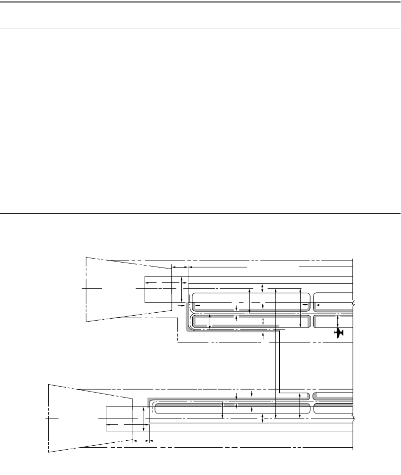
a function of approach speed and aircraft size. Figure 59.40 presents the overall dimensions that are
involved in parallel railways and taxiways, while Table 59.30 shows the standards for airports that service
aircraft in the approach speed categories C and D. Figure 59.41 shows the plan view of major runway
FIGURE 59.39 Takeoff weight as a function of flap angle setting.
Aircraft Constrained
Runway Constrained
(9500 ft.)
Flap Setting on Take-off in Degrees
5101520
25
185
180
175
170
165
160
155
150
M
A
T
O
W
i
n
T
h
o
u
s
a
n
d
s
o
f
p
o
u
n
d
s
Allowable Take-off Weight vs. Flap Angle
727-200 Aircraft, JTD8-15 Engines
(Runway = 9,500 feet)
© 2003 by CRC Press LLC

59-58 The Civil Engineering Handbook, Second Edition
elements. The runway protection zone was shown in Fig. 59.26. There are similar data for airports serving
approach categories A and B. These dimensions are all listed in the airport design computer program
output [FAA, 1991c].
Runway Gradients
Longitudinal Gradient
The desire at any airport site is to have the runways and taxiways as level as possible, allowing for drainage
with the design of the transverse grade. In many locations the grading for a perfectly level site would be
too expensive when most aircraft can easily accept 1% grade. Where longitudinal grades are used,
TABLE 59.28 Aircraft Performance, Takeoff Boeing 727–200, JT8D-15 Engine, 15° Flaps
Maximum Allowable Takeoff Weight (1000 lb)
Airport Elevation (100 ft)
Te mp (°F) 0 1000 2000 3000 4000 5000 6000 7000
50 197.0 197.0 197.0 193.4 186.9 180.2 173.5 166.9
60 197.0 197.0 197.0 193.4 186.9 180.2 173.5 166.9
70 197.0 197.0 197.0 193.4 186.9 180.2 173.5 166.9
80 197.0 197.0 196.2 189.0 182.2 175.8 169.5 163.4
90 197.0 195.8 188.7 181.9 175.4 (A) 169.0 162.9 156.8
100 194.5 187.7 181.0 174.5 168.2 162.0 156.0 150.2
110 186.5 179.7 173.1 166.8 159.7 154.8 149.0 143.4
Reference Factor
Airport Elevation (1000 ft)
Te mp (°F) 0 1000 2000 3000 4000 5000 6000 7000
50 58.6 61.6 65.7 70.7 76.5 83.0 90.2 97.9
60 58.4 62.0 66.3 71.3 77.0 83.4 90.5 98.4
70 59.4 63.5 68.1 73.2 78.9 85.4 92.6 100.6
80 61.4 65.9 70.8 76.2 82.2 88.9 96.4 104.9
90 64.5 69.4 74.7 80.5 86.9 (B) 94.0 102.0 111.0
100 68.7 73.9 79.6 85.9 92.9 100.7 109.4 119.0
110 74.0 79.4 85.5 92.5 100.3 109.0 118.5 129.0
Runway Length (1000 ft)
Reference Factor
We ight (1000 lb) 58 68 78 86.9 88 98 108 118 128
130 3.96 4.55 5.20 5.90 6.61 7.28 7.88 8.39
135 4.23 4.89 5.59 6.30 7.00 7.66 8.28 8.82
140 4.51 5.25 5.99 6.73 7.44 8.13 8.78 9.39
145 4.81 5.63 6.42 7.19 7.94 8.67 9.38 10.08
150 5.13 6.02 6.87 7.69 8.49 9.29 10.09 10.90
155 5.46 6.44 7.35 8.23 9.10 9.98 10.89 11.85
160 5.82 6.86 7.85 8.81 9.77 10.76 11.80 12.93
165 6.18 7.31 8.38 9.31 9.42 10.49 11.61 12.81 14.13
166.5 9.50(D)
170 6.57 7.77 8.92 9.95 10.08 11.26 12.53 13.92
175 6.97 8.25 9.49 10.62 10.76 12.10 13.54
175.4 10.68(C)
180 7.37 8.74 10.09 11.34 11.49 12.98
185 7.83 9.25 10.71 12.25 13.92
190 8.28 9.78 11.35 13.05
Source: FAA, Runway Length Requirements for Airport Design, Advisory Circular AC150/5325-4A, 1990a.
© 2003 by CRC Press LLC
Airport Planning and Design 59-59
parabolic vertical curves are used for geometric design, as shown in Fig. 59.42. The penalty for gradients
is to reduce the effective runway length by 10 feet per foot of difference between maximum and minimum
elevation of the runway [FAA, 1992]. Table 59.31 defines the gradients in terms of approach category.
For example, if the runway at TBA were 10,200 feet long but there was a differential between the
highest point and the lowest point along the runway of 70 feet, the effective runway length for MATOW
calculations would be 9500 (10,200 – 70 ¥ 10) feet.
TABLE 59.29 Range/Payload Calculation for 727-200 with JT8D-15 Engines and 15° Flaps
Characteristic Units/Notes
Max Payload
Case
1500-Mile-
Range Case
50% Load
Factor Case
Maximum allowable takeoff
weight
Table 59.30 gives 175,400 lb as the maximum takeoff weight; however, that much weight
requires a runway length of 10,680 ft; see Table 59.30(C)
Takeoff weight Calculated using reference factor
(86.9): Table 59.30 (D)
166,500 lb
[76,650 kg]
166,500 lb
[76,050 kg]
166,500 lb
[76,050 kg]
Typical operating empty weight
plus reserve
Given (1.25 h of fuel reserve required
for domestic flight)
109,211 lb
[49,650 kg]
109,211 lb
[49,650 kg]
109,211 lb
[49,650 kg]
Remaining for payload and fuel 57,289 lb 57,289 lb 57,289 lb
[26,040 kg] [26,040 kg] [26,040 kg]
Passenger Maximum = 162 162 (100%
load factor)
141 (87%
load factor)
81 (50%
load factor)
162 maximum passengers 200 lb [90 kg] per passenger 32,400 lb
a
24,289 lb 16,200 lb
[14,730] [11,040 kg] [7365 kg]
Max belly air cargo Fill to structural payload limit of
40,339 lb
a
[18,335 kg]
7,939 lb
[3605 kg]
0 lb 0 lb
Amount of fuel 16,950 lb 33,000 lb 41,089 lb
[7,700 kg] [15,000 kg] [18,675 kg]
Distance of market served range Fuel rate given 22 lb/mile [6.2 kg/km] 770 miles 1500 miles 1867 miles
[1240 km] [2415 km] [3005 km]
a
Calculated from data in FAA, Runway Length Requirements for Airport Design, Advisory Circular AC150/5325-4A, 1990a.
FIGURE 59.40 Runway and taxiway dimensions. (From FAA, Airport Design, Advisory Circular AC150/5300-13,
change 1, 1991c.)
BUILDING RESTRICTION LINE (BRL)
200'
60 m
P
RUNWAY
PROTECTION
ZONE
BRL
C
A-RUNWAY LENGTH
B
B
RUNWAY CENTERLINE
E
EWD
E
J
K
E
BRL
H
AREA RESERVED
FOR FUTURE AIRPORT
DEVELOPMENT
BRL BRL
E
G
B
W
D
C
P
RUNWAY
PROTECTION
ZONE
200'
60 m
A-RUNWAY LENGTH
BRLBRL
NOTES: 1. DIMENSION LETTERS ARE KEYED TO TABLES 2-1, 2, 3, 5; 3-1,2,3; 4-1
2. SHADED AREA SURROUNDING TAXIWAYS DELINEATED THE LIMITS OF THE TAXIWAY SAFETY AREA.
3. PREFERRED LOCATION FOR BUILDING AND AIRPLANE PARKING AREA IS MIDPOINT OF RUNWAY.
THE SIZE AND SHAPE ARE VARIABLE AS REQUIRED.
© 2003 by CRC Press LLC

59-60 The Civil Engineering Handbook, Second Edition
Line of Sight
The line-of-sight requirements also determine the acceptable profile of the runway. Any two points 5 feet
above the runway centerline must be mutually visible for the entire runway or if on a parallel runway or
taxiway for one half of the runway. Likewise, there needs to be a clear line of sight at the intersection of
two runways, two taxiways, and taxiways that cross an active runway. Most line-of-sight requirements
are within 800 to 1350 feet of the intersection, depending on the configuration.
Transverse Gradients
The transverse gradients are important to ensure adequate drainage from the runways and the taxiways.
The plan view shown in Fig. 59.41 indicates the typical gradients that are included in runways and
taxiways. The chief concern is drainage and the line of sight to adjacent runways or taxiways.
TABLE 59.30 Separation Standards for Transport Airport Design (Approach Categories C and D)
Design Item
Figs. 59.40 and
59.41 Dimensions
Airplane Design Group
IIIIII IV V VI
For Runways
Safety area width (ft) C 500 500 500 500 500 500
Safety area length beyond runway end (ft) P 1000 1000 1000 1000 1000 1000
Width (ft) B 100 100 100 150 150 200
Shoulder width (ft) 10 10 20 25 35 40
Blast pad width (ft) 100 100 140 200 220 280
Object-free area width (ft) Q 800 800 800 800 800 800
Object-free area length beyond runway end R 1000 1000 1000 1000 1000 1000
Nonprecision instrument and visual runway
centerline to:
Parallel runway (simultaneous VFR ops.
b
)
(ft)
H 700 700 700 700 1200 1200
Taxiway/taxilane centerline (ft) D 300 300 400 400 400–500
a
600
Aircraft parking area (ft) G 400 400 500 500 500 500
Precision instrument runway centerline to:
Parallel runway (simultaneous IFR ops.
c
)H4300 4300 4300 4300 4300 4300
Taxiway/taxiline centerline (ft) D 400 400 400 400 400–500
a
600
Aircraft parking area (ft) G 500 500 500 500 500 500
For Taxiways
Safety area width (ft) E 49 79 118 171 214 262
Width (ft) W 25 35 50 75 75 100
Edge safety margin (ft) 5 7.5 10 15 15 20
Shoulder width 10 10 20 25 35 40
Object-free area width (ft) 89 131 186 259 320 386
Centerline to:
Parallel taxiway/taxilane centerline (ft) J 69 105 152 215 267 324
Fixed or movable object (ft) K 44.5 65.5 93 129.5 160 193
For Taxilanes
Object-free area width (ft) 79 115 162 225 276 334
Centerline to:
Parallel taxiway/taxiline centerline (ft) 64 97 140 198 245 298
Fixed or movable object (ft) 39.5 57.5 81 112.5 138 167
Note: ops. = operations.
a
400 ft applies for airports from sea level to 1345-ft altitude; 450 ft from 1345- to 6560-ft altitudes; and 500 ft for altitudes
greater than 6560 ft.
b
Separations less than 2500 ft require wake turbulence procedures.
c
Other separations are possible for simultaneous departures only: with radar 2500 ft, without radar 3500 ft.
Source: FAA, Airport Design, Advisory Circular AC150/5300-13, change 1, 1991c.
© 2003 by CRC Press LLC