Wai-Fah Chen.The Civil Engineering Handbook
Подождите немного. Документ загружается.

Airport Planning and Design 59-61
Drainage
Drainage on the airport surface is a prime requisite for operational safety and pavement durability. The
drainage design is handled like most drainage for streets and highways. Avoidance of ponding and erosion
of slopes that would weaken pavement foundations is critical for design. Because of the need for quick
and total water removal over the vast, relatively flat airport surface, an integrated drainage system is a
must. Runoff is removed from the airport by means of surface gradients, ditches, inlets, an underground
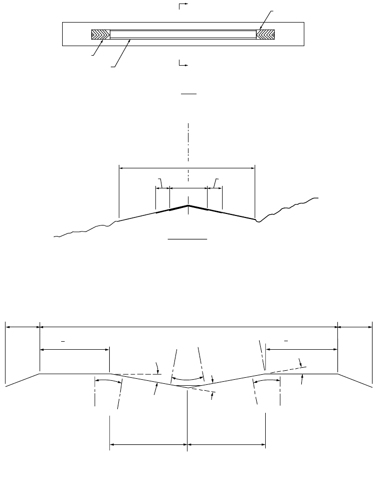
FIGURE 59.41 Plan and cross section view of the runway elements. (From FAA, Airport Design, Advisory Circular
AC150/5300-13, change 1, 1991c.)
FIGURE 59.42 Longitudinal grade criteria for airports (C and D approach criteria). (From FAA, Airport Design,
Advisory Circular AC150/5300-13, change 1, 1991c.)
STRUCTURAL PAVEMENT
RUNWAY SAFETY AREA
A
A
SHOULDER
BLAST
PA S
BLAST
PA S
PLAN
RUNWAY SAFETY AREA
SHOULDER
SHOULDER
STRUCTURAL
PAVEMENT
SECTION A-A
200'
(60 m)
END OF RWY.
200'
(60 m)
END OF RWY.
0% TO - 3%
0% TO - 3%
0% TO 0.6%
0% TO - 1.5%
0% TO 1.5%
END OF RUNWAY
END OF RUNWAY
PROFILE OF RUNWAY CENTERLINE
GRADE CHANGE
P.C.
P.T .
P.C.
P.T .
P.T .
VERT
CURVE
LENGTH
P.C.
P.I.
VERT
CURVE
LENGTH
VERT
CURVE
LENGTH
GRADE CHANGE
GRADE CHANGE
DIST. BETWEEN
CHANGE IN GRADE
DIST. BETWEEN
CHANGE IN GRADE
1.5 % MAX.
P.I.
0% TO 0.8%
MINIMUM DISTANCE BETWEEN CHANGE IN GRADE = 1000' (300 m) x SUM OF GRADE CHANGES (IN PERCENT).
MINIMUM LENGTH OF VERTICAL CURVES = 1000' (300 m) ¥ GRADE CHANGE (IN PERCENT)
1
4
1
4
© 2003 by CRC Press LLC

59-62 The Civil Engineering Handbook, Second Edition
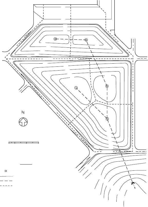
system of pipes, and retention ponds. Figure 59.43 shows one portion of an airport drainage system.
Because of their large contiguous area, aprons are critical and must have an adequate sewer system.
Runoff water treatment is required when there are fuel spills or during the winter, when a deicing chemical
is used.
Lighting and Signing
Runway
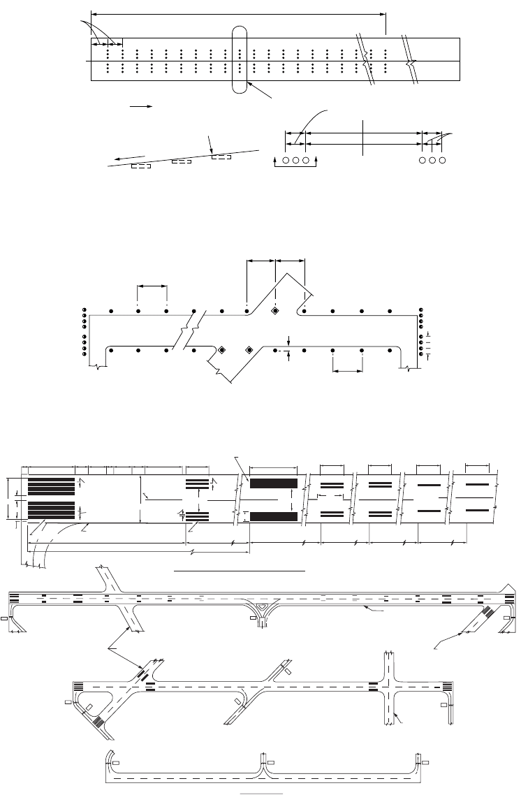
Lighting and signing of the runway shown in Fig. 59.44 provide the pilot visual cues to ensure alignment
with the runway, lateral displacement, and distance along the runway. Runway edge lights standing no
more than 30 inches and no more than 10 ft from the runway edge are 200 ft or less apart and are white,
except for the last 2000 ft of runway, when they show yellow. Centerline lights are white and set 2 ft off
the centerline of the runway, except for the last 3000 ft. In this area they are alternating red and white
for 2000 ft, and they are red 1000 ft from the runway end. When aircraft are approaching the runway to
land, the pilot determines the threshold because it is marked by a bar of green lights. However, those
lights show red when aircraft approach the end of the runway from the other direction. As shown in
Fig. 59.45, painted markings also indicate where the aircraft is relative to distance past the threshold.
Exits, particularly high-speed exits, are clearly marked by signs placed at a distance of 1200 to 1500 ft
before the exit.
Airfield
The airfield is marked with a variety of signs delineating the taxiways, stoplines, holding areas, and the
like. Blue lights indicate taxiway edges. Stop bars before crossing or entering an active runway are yellow.
There have been a number of accidents and near accidents on the ground, especially when the visibility
is low. The FAA is experimenting with a new lighted stop bar. The controller controls the lights. When
the bar is lit there are now center lights ahead, creating a black hole effect. Once the aircraft is permitted
on the runway, the light bar is extinguished and the taxiway/runway lights are illuminated to guide the
pilot onto the runway for takeoff [FAA, 1993b].
Typical airfield markings give the pilot directions to the ramp, parking areas, fuel, gates, areas for
itinerant aircraft, ramps for military aircraft, cargo terminals, international terminals, and other airside
functions. Visual cues also aid the pilot in docking the aircraft at the gate. Generally there is also an
airline ground employee with handheld signal lights to direct the pilot as the aircraft pulls into the gate.
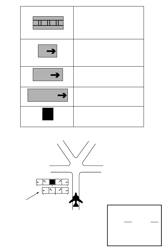
Figure 59.46 shows the FAA’s 1993 guide to airfield signs.
Approach to the Runway
The approach lighting system (ALS) dictates the navigation and approach capability. Light bars may
extend as much as 3000 feet from the threshold along the aircraft’s desired glide path. Lighting systems
TABLE 59.31 Longitudinal Gradients for Runways and Taxiways
Design
Item
Aircraft
Served
Maximum Rate
of Change
Ve rtical Curve
(ft/% change) Remarks
Runway A and B ±2% 300 Vertical curve not needed for changes less than 0.4%
Runway C and D ±1.5% 1000 Grade on first and last one fourth of runway ±0.8%;
vertical curve not needed for changes less than 0.4%
Runway A and B ±2% 100 Elevation between taxiway and corresponding point
on parallel runway
Taxiway C and D ±1% 100 Taxiway or apron edge is 1.5% of shortest distance
between the two
ApronA and B ±2% Consistent with drainage
ApronC and D ±1% Direct drainage away from building
Source: FAA, Airport Design, Advisory Circular AC150/5300-13, change 1, 1991c.
© 2003 by CRC Press LLC
Airport Planning and Design 59-63
are available to provide runway glide slope cues indicating whether the pilot is above, below, right, or
left of the hypothetical wire representing the proper descent trajectory. The visual approach slope indi-
cator systems (VASIS) provide at the side of the runway red and white light bars.
The precision approach path indicator (PAPI) system provides upper and lower lights of red and white
that in various combinations indicate whether the pilot is too low or too high. For example, an all-white
bar indicates the aircraft is on a glide slope greater than 3.5 degrees, while an all-red bar is less than
2.5 degrees. Equal red and white indicates the aircraft is on the 3-degree glide slope.
Positioning along the glide path is accomplished by the use of light bars extending from the runway
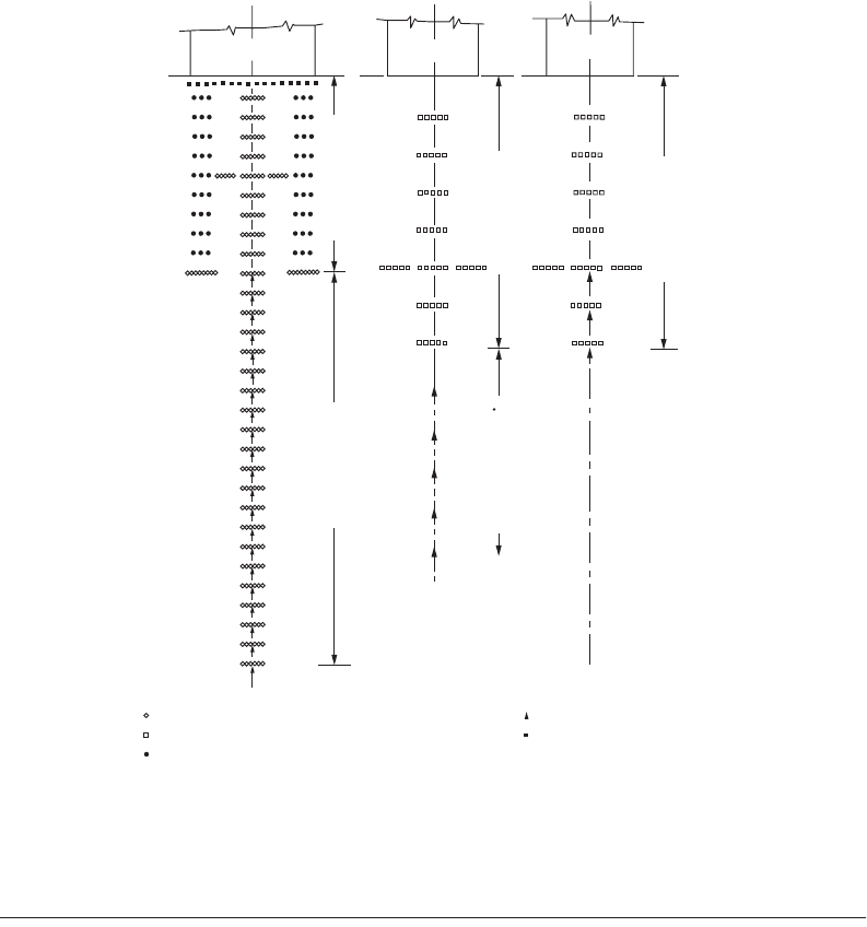
along the flight path. There are several different approach lighting systems, as suggested in Fig. 59.47.
For precision approaches (category I, II, or III) ILS, the high-intensity approach lighting system with
sequenced flashing lights (ALSF) is employed. The ALS consists of light bars 3000 ft from the threshold.
From 3000 to 1000 ft the lights are a sequenced flasher that gives the appearance of a rolling ball leading
to the runway centerline. From 1000 ft (inner marker) to the threshold there are white light bars in the
FIGURE 59.43 Portion of an airport showing drainage design. (From FAA, Airport Drainage, Advisory Circular
AC150/5320-5B, 1970.)
540
539
540
540
542
541
541
541
540
539
539
538
538
538
537
537
536
536
536
540
541
542
541
539
538
537
536
540
541
542
539
538
537
536
535
530
525
536
535
537
510'-30"
30+57
S= 0.0016
730'-30"
S= 0.0018
1143'-60"
S = 0.0008
550'-54"
S = 0.0007
852'-48"
S= 0.0008
# 12
# 13
535
# 10
# 11
25+47
7 + 30
16 + 95
535
# 9
11 + 95
542
541
APRON
TAXIWAY
TAXIWAY
TA XI WAY
TAXIWAY
TA XI WAY
TAXIWAY
0+00
OUTFALL
GRAPHIC SCALE
100 0 200 400 FEET
i
L E G E N D
Inlet
Ditch
Storm Drain
Limits of Contributing Drainage Area
© 2003 by CRC Press LLC
59-64 The Civil Engineering Handbook, Second Edition
FIGURE 59.44 Runway lighting. (From FAA, Standards for Airport Markings, Advisory Circular AC150/5340-IG,
1993c.)
FIGURE 59.45 Marking along the runway. (From FAA, Standards for Airport Markings, Advisory Circular
AC150/5340-IG, 1993c.)
MAX
200
´
MAX
200¢
MAX
200¢
MAX
200¢
10¢
MAX
10¢ 0C.
100¢
± 25¢
Direction of instrument
approach
See detail A
Measure tolerance
at this edge
Section x-x
Light bar Light bar
10¢ 10¢
5¢
± 1/4¢¢
AT 5¢
2 spaces
36¢
Runway
Detail A
3000¢
30 light bars equally spaced at 100 ft intervals
Slope
XX
34
16
VISUAL RUNWAY
21
20
VISUAL RUNWAY
2
R
21
L
NONPRECISION INSTRUMENT RUNWAY
PRECISION INSTRUMENT RUNWAY
STABILIZED SHOULDER
NONPRECISION INSTRUMENT
RUNWAY
20
L
75'75'75'75'
150'
500'500'500'500'
500'
500'
1000'
130'
16
57
7'
THRESHOLD MARKER
SIDE STRIPE 5' WIDE
12' STRIPES
5' SPACES
144'
20' 150' 40' 60' 20' 60' 40' 120' 75'
72'
6'
STRIPES
5 SPACES
CENTERLINE
3' WIDE
30'
TOUCHDOWN ZONE
MARKER
FIXED DISTANCE MARKING
72'
80'
PRECISION INSTRUMENT RUNWAY MARKINGS
33
© 2003 by CRC Press LLC
Airport Planning and Design 59-65
center and bars of red lights on either side of the centerline spaced 100 ft apart. An extra light bar is
placed at 500 ft to provide an added visual cue.
MALSR is a medium-intensity ALS with a runway alignment indicator light. It is the U.S. standard
for ILS operations during category I visibility minima. Five sequenced lights begin at 2400 ft from the
threshold and extend to 1400 ft. Thereafter eight flashing light bars are installed along the extended
runway centerline at 200-ft spacing extending to the threshold. Other medium-intensity approach lighting
systems are for nonprecision approaches and consist of the white center marking bars sometimes aug-
mented with the sequenced white flashers.
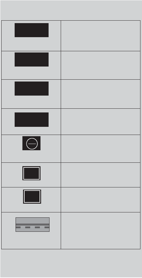
FIGURE 59.46 Guide to airfield signs. (From FAA, Standards for Airport Markings, Advisory Circular AC150/5340-
IG, 1993c.)
4 - 22
4 - 22
4 - APCH
ILS
B
22
GUIDE TO AIRFIELD SIGNS (U.S.)
SIGN and LOCATION PILOT ACTION or SIGN PURPOSE
Controlled Airport - Hold unless
ATC clearance has been received.
Uncontrolled Airport - Proceed
when no traffic conflict exists.
Taxing - Same action as above.
Taking Off or Landing - Disregard
unless a “Land, Hold Short”
clearance has been accepted.
Controlled Airport - Hold when
instructed by ATC.
Uncontrolled Airport - Proceed
when no traffic conflict exists.
Hold when approaches are being
made with visibility less than 2
miles or ceiling less than 800 feet.
Do not enter.
Identifies taxiway on which
aircraft is positioned.
Identifies runway on which
aircraft is positioned.
These signs are used on controlled
airports to identify the boundary of the
runway protected area. It is intended
that pilots exiting this area would use
this sign as a guide to judge when the
aircraft is clear of the protected area.
Edge of Protected Area
for Runway
Notes:
1. See the
Airman’s Information Manual
/for additional information on airfield signs.
2. The signs shown on this guide comply with FAA standards. In some cases ICAO’s
proposed sign standards differ with FAA’s. The asterisk (
*
) in the left column denotes
these cases so the pilot can be aware that some differences may be encountered
outside the United States.
*
*
*
On Taxiways at
Intersection with a Runway
Runway/Runway
Intersection
Taxiway in Runway
Approach or Departure Area
ILS Critical Area
Areas where Aircraft are
Forbidden to Enter
Taxiway
Runway
© 2003 by CRC Press LLC
59-66 The Civil Engineering Handbook, Second Edition
Runway Pavement Design
Pavement design methods are based on the gross weight of the aircraft. Since it is impracticable to develop
design curves for each type of aircraft, composite aircraft are determined and loads are converted from
the actual aircraft to the design aircraft, the design aircraft being the one that requires the greatest
thickness of pavement. The traffic forecast, which includes the mix of aircraft anticipated, is converted
to a traffic forecast of equivalent annual departures.
FAA Advisory Circular AC150/5320-6C CHG 2 [1978] presents a number of curves to be used to design
the pavement thickness for both flexible and rigid pavements. The process is outlined in Chapter 62.
FIGURE 59.46 (continued).
Arrangement of Signs at an Intersection
Time Conversion to UTC (Z)
Notes: Orientation of signs is
from left to right in a clockwise
manner. Left Turn Signs are on
the left of the Location Sign and
Right Turn Signs are on the right
side of the Location Sign.
SIGN and LOCATION
4
A
TERM
22
B
E
EE
E
F
F
T
T
*
Edge of ILS Critical Area
Taxiways and Runways
Taxiways and Runways
Taxiway
Runway
Provides remaining runway length in
1,000 feet increments.
Provides general taxiing direction to
identified destination
Provides general taxiing direction to
named runway.
On Taxiways - Provides direction to
turn at next intersection to maneuver
aircraft onto named taxiway.
On Runways - Provides direction to turn
to exit runway onto named taxiway
These signs are used on controlled
airports to identify the boundary of
the ILS critical area. It is intended that
pilots exiting this area would use this
sign as a guide to judge when the
aircraft is clear of the ILS critical area.
F
T
E
E
A
EDT........... 4 MDT...........6
EST........... 5 MST...........7
CDT...........5 PDT...........7
CST........... 6 PST...........8
Hawaii & Alaska.................10
Alternate array of signs
shown to illustrate sign
orientation when Location
Sign not installed.
For additional copies contact:
FAA/ASF-20,
800 Independence Avenue, S.W.,
Washington, DC 20591
(202) 267-7770
Add
hrs.
Add
hrs.
PILOT ACTION or SIGN PURPOSE
© 2003 by CRC Press LLC
Airport Planning and Design 59-67
59.9 Airport Plans
Upon completion of the inventory, forecasting, requirements analysis, and site evaluation, the master
planning proceeds to the synthesis of airside and landside concepts and plans. These include an airport
layout plan and an approach and clear zone plan. Other plans could include the site plan, the access plan,
and the environmental plan.
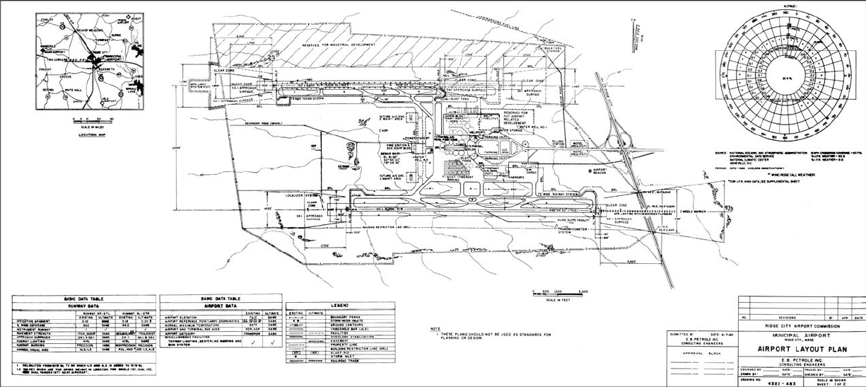
Airport Layout Plan
The airport layout plan is a graphic representation to scale of existing and future airport facilities on the
airport. An example is presented in Fig. 59.48. It will serve as the airport’s public document, giving
aeronautical requirements as well as pertinent clearance and dimensional data and relationships with the
external area. The airfield configuration of runways, taxiways, aprons, and the terminal are shown
schematically. The airport layout plan (usually a 24- by 36-in. plate with minimum lettering of 120 in.)
should include, as a minimum, the following:
FIGURE 59.47 FAA approach light systems. (From FAA, Standards for Airport Markings, Advisory Circular AC150/5340-
IG, 1993c.)
ALSF-II MALSR
MALSF
1400 ft (420 m)
1400 ft (420 m)
2000 ft (600 m) 1000 ft (300 m)
1000 ft (300 m)
Steady burning red lights.
High-intensity steady burning white lights.
Medium-intensity steady burning white lights. ALS threshold light bar.
Sequenced flashing lights.
© 2003 by CRC Press LLC
59-68 The Civil Engineering Handbook, Second Edition
FIGURE 59.48 Sample airport layout plan. (From FAA, Airport Master Plans, Advisory Circular AC150/5070-6A, 1985.)
© 2003 by CRC Press LLC
Airport Planning and Design 59-69
•Airport layout details
•Runways, taxiways, blast pads, stabilized shoulders, runway safety areas, buildings, NAVAIDs,
parking areas, road lighting, runway marking, pipelines, fences, major drainage facilities, wind
indicators, and beacon
•Prominent features such as trees, streams, ponds, ditches, railroads, power lines, and towers
•Revenue-producing nonaviation property
•Areas reserved for future development, such as FBO facilities and fuel farms
•Areas reserved for nonaviation development
•Existing ground contours
•Fueling facilities and tie-down areas
•Airport boundaries
•Clear zones and associated approach surfaces
•Airport reference point
• Latitude, longitude, and elevation of existing and ultimate runway ends and thresholds
•True azimuth of the runways (measured from true north)
•Pertinent dimensional data
•Location map depicting the airport with surrounding cities, railroads, major roads, and tall towers
within 25 to 50 miles of the airport
•Vicinity map
•Basic data table on existing and future airport features, including elevation, reference point coor-
dinates, magnetic variations, maximum daily temperature for the hottest month, airport and
terminal navigational aids, runway identification, longitudinal gradients, percent wind coverage,
instrument runways, pavement type, pavement strength in gross weight, type of main gear (single,
dual, or dual tandem), approach surfaces, runway lighting, runway marking, electronic and visual
approach aids, and weather facilities
•Wind rose with runway orientation superimposed
•Designated instrumented runway [FAA, 1985]
Approach and Runway Clear Zone Plan
The approach and clear zone drawing permits the planner to determine how the airport will interface
with the surrounding area in terms of safe flight. An example is presented in Fig. 59.49. It includes:
•Area under the imaginary surfaces defined in U.S. Code FAR, Part 77 [1975]
•Existing and ultimate approach slopes or slope protection established by local ordinance
•Runway clear zones and approach zones showing controlling objects in the airspace
•Obstructions that exceed the criteria
•Tall smokestacks, television towers, garbage dumps, landfills, or other bird habitats that could
pose a hazard to flight
Other Plans
Terminal Area Plan
The terminal area plan usually consists of a conceptual drawing showing the general plan for the terminal,
including its possible expansion. Under some changes the terminal modification will have a major impact
on the taxiway and apron and will be reflected in an altered ALP.
© 2003 by CRC Press LLC

59-70 The Civil Engineering Handbook, Second Edition
FIGURE 59.49 Sample runway and approach plan. (From FAA, Airport Master Plans, Advisory Circular AC150/5070-6A, 1985.)
© 2003 by CRC Press LLC