Wai-Fah Chen.The Civil Engineering Handbook
Подождите немного. Документ загружается.


Physical Water and Wastewater Treatment Processes 9-59
The collection mechanisms in circular tanks have no bearings under water and are less subject to
corrosion, reducing maintenance. However, center-feed tanks tend to exhibit streaming, especially in
tank diameters larger than about 125 ft. Streaming is reduced in peripheral feed tanks and in center feed
tanks with baffles (Joint Committee, 1990).
The design principles used for rectangular tanks also apply, with a few exceptions, to circular tanks.
Free, Nonflocculent Settling
The analysis of particle trajectories for circular tanks is given by Fair, Geyer, and Morris (1954) for center-
feed, circular clarifiers. The trajectory of a freely settling, nonflocculent particle curves downwards,
because as the distance from the center-feed increases, the horizontal water velocity decreases. At any
point along the trajectory, the slope of the trajectory is given by the ratio of the settling velocity to the
water velocity:
(9.172)
where H = the water depth in the settling zone (m or ft)
Q = the flow through the settling zone (m
3
/s or ft
3
/sec)
r = the distance from the center of the tank (m or feet)
U
r
= the horizontal water velocity at r (m/s or ft/sec)
n
s
= the particle’s settling velocity (m/s or ft/sec)
z = the elevation of the particle about the tank’s bottom (m or ft)
The minus sign on the right-hand-side is needed, because the depth variable is positive upwards, and
the particle is moving down.
Equation (9.172) can be solved for the critical case of a particle that enters the settling zone at the
water surface and reaches the bottom of the settling zone at its outlet cylinder:
(9.173)
where r
i
= the radius of the inlet baffle (m or ft)
r
o
= the radius of the outlet weir (m or ft).
The denominator in Eq. (9.173) is the plan area of the settling zone. Consequently, the critical settling
velocity is equal to the settling zone overflow rate.
The analysis leading to Eq. (9.173) also applies to tanks with peripheral feed and central takeoff. The
only change required is the deletion of the minus sign in the right-hand side of Eq. (9.172), because the
direction of the flow is reversed, and the slope of the trajectory is positive in the given coordinate system.
Furthermore, the analysis applies to spiral flow tanks, if the integration is performed along the spiral
stream lines. Consequently, all horizontal flow tanks are governed by the same principle.
Free, Flocculent Settling
The trajectories of nonflocculating particles in a circular clarifier are curved in space. However, if the
horizontal coordinate were the time-of-travel along the settling zone, the trajectories would be linear.
This can be shown by a simple change of variable:
(9.174)
This means that Fig. 9.7 also applies to circular tanks, if the horizontal coordinate is the time-of-travel.
Furthermore, it applies to flocculent and nonflocculent settling in circular tanks.
dz
dr
v
U
Hv
Q
s
r
s
=- =-
2p
v
Q
rr
o
oi
=
-
()
p
22
dz
dt
dz
dr
dr
dt
v
U
Uv
s
r
rs
= ◊ =- ◊ =-
© 2003 by CRC Press LLC
9-60 The Civil Engineering Handbook, Second Edition
Equation (9.156) applies to circular tanks with uniform feed over the inlet depth, whether they are
center-feed, peripheral-feed, or spiral-flow tanks.
Unfortunately, the inlet designs of most circular clarifiers do not produce a vertically uniform feeding
pattern. Usually, all of the flow is injected over a small portion of the settling zone depth. As long as the
flow is injected at the top of the settling zone, this does not change matters, but other arrangements may.
One case where Camp’s formula for clarifier efficiency does not apply is the upflow clarifier. However,
this is also a case of hindered settling, and it will be discussed later.
The plan area of the circular settling zone is determined by the overflow rate, and this rate will be
equal to the one used for a rectangular tank having the same efficiency. The design is completed by
choosing a settling zone depth or a detention time. No general analysis for the selection of these
parameters has been published, and designers are usually guided by traditional rules of thumb. The
traditional rule of thumb in the United States is a detention time of 2 to 4 hr (Joint Task Force, 1969).
Many regulatory agencies insist on a 4 hr detention time (Water Supply Committee, 1987).
Design of High-Rate, Tube, or Tray Clarifiers
“High-rate” settlers, also known as “tray” or “tube” settlers, are laminar flow devices. They eliminate
turbulence, density currents, and streaming, and the problems associated with them. Their behavior is
nearly ideal and predictable. Consequently, allowances for nonideal and uncertain behavior can be
eliminated, and high-rate settlers can be made much smaller than conventional rectangular and circular
clarifiers; hence, their name.
Hayden (1914) published the first experimental study of the efficiency of high-rate clarifiers. His unit
consisted of a more-or-less conventional rectangular settler containing a system of corrugated steel sheets.
This is a form of Camp’s tray clarifier. The sheets were installed 45° from the horizontal, so that particles
that deposited on them would slide down the sheets into the collection hoppers below. The sheets were
corrugated for structural stiffness. The high-rate clarifier had removal efficiencies that were between 40
and 100% higher than simple rectangular clarifiers having the same geometry and dimensions and
treating the same flow.
Nowadays, Hayden’s corrugated sheets and the Hazen–Camp trays are replaced by modules made out
of arrays of plastic tubes. The usual tube cross section is an area-filling polygon, such as the isoceles
triangle, the hexagon, the square, and the chevron. Triangles, squares, and chevrons are preferred, because
alternate rows of tubes can be sloped in different directions, which stiffens the module and makes it self-
supporting. When area-filling hexagons are used, the alternate rows interdigitate and must be strictly
parallel. Alternate rows of hexagons can be sloped at different angles, if the space-filling property is
sacrificed.
Sedimentation
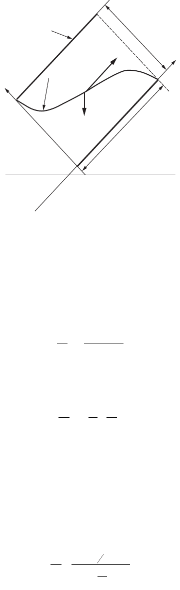
Consider a particle being transported along a tube that is inclined at an angle q from the horizontal. Yao
(1970, 1973) analyzes the situation as follows. Refer to Fig. 9.9. The coordinate axes are parallel and
perpendicular to the tube axis. The trajectory of the particle along the tube will be resultant of the
particle’s settling velocity and the velocity of the water in the tube:
(9.175)
(9.176)
where t =time (sec)
u = the water velocity at a point in the tube (m/s or ft/sec)
n
s
= the particle’s settling velocity (m/s or ft/sec)
n
x
= the particle’s resultant velocity in the x direction (m/s or ft/sec)
dx
dt
vuv
xs
==-sinq
dy
dt
vv
ys
==-cosq
© 2003 by CRC Press LLC
Physical Water and Wastewater Treatment Processes 9-61
n
y
= the particle’s resultant velocity in the y direction (m/s or ft/sec)
q = the angle of the tube with the horizontal (rad)
Equations (9.175) and (9.176) may be combined to yield the differential equation of the trajectory of
a particle transitting the tube:
(9.177)
The water velocity u varies from point to point across the tube cross section. For fully developed
laminar flow in a circular tube, the distribution is a parabola (Rouse, 1978):
(9.178)
where d
t
= the tube diameter (m or ft)
U
t
= the mean water velocity in the tube (m/s or ft/sec)
y = the distance from the tube invert (m or ft)
The critical trajectory begins at the crown of the tube and ends at its invert. Substituting for u and
integrating between these two points yields the following relationship between the settling velocity of a
particle that is just captured and the mean water velocity in a circular tube (Yao, 1970):
Laminar flow in circular tubes:
(9.179)
where L
t
= the effective length of the tube (m or ft).
FIGURE 9.9 Tr ajectory of the critical particle in a tube. [Yao, K.M. 1970. Theoretical Study of High-Rate Sedimen-
tation, J. Water Pollut. Control Fed., 42 (no. 2, part 1): 218.]
trajectory
tube
wall
horizontal
y
L
t
ν
s
d
t
x
u
θ
dy
dx
v
uv
s
s
=-
-
cos
sin
q
q
u
U
y
d
y
d
ttt
=-
Ê
Ë
Á
ˆ
¯
˜
8
2
2
v
U
L
d
s
t
t
t
=
+ ◊
4
3
sin cosqq
© 2003 by CRC Press LLC
9-62 The Civil Engineering Handbook, Second Edition
Yao (1970) has performed the same analysis for other cross-sectional shapes, and the equations differ
only in the numerical value of the numerator on the right-hand side.
Laminar flow in square tubes:
(9.180)
where a = the length of one side of the square cross section (m or ft).
Laminar flow between parallel plates, or for laminar flow over a plane, or for an idealized flow
that has a uniform velocity everywhere:
(9.181)
where h
p
= the thickness of the flow (m or ft).
This critical velocity may be related to the tube overflow rate. The definition of the overflow rate for
a square tube is:
(9.182)
where v
ot
= the tube overflow rate (m/s or ft/sec).
Therefore,
(9.183)
In the ideal Hazen–Camp clarifier, the critical settling velocity is equal to the tank overflow rate. This
is not true for tubes. Tubes are always installed as arrays, and the critical velocity for the array is much
less than the tank overflow rate. The number of tubes in such an array can be calculated as follows. First,
the fraction of the settling zone surface occupied by the tube ends is less than the plan area of the zone,
because the inclination of the tubes prevents full coverage. The area occupied by open tube ends that
can accept flow is:
(9.184)
where A
0
= the area of the settling zone occupied by tube ends (m
2
or ft
2
)
L = the length of the settling zone (m or ft)
L
t
= the length of the tubes (m or ft)
W = the width of the settling zone (m or ft)
q = the angle of the tubes with the horizontal plane (rad)
The number of square tubes in this area is:
v
U
L
a
s
t
t
t
=
+ ◊
11
8
sin cosqq
v
U
L
h
s
t
t
p
=
+ ◊
1
sin cosqq
tube overflow rate
flow through tube
horizontally projected area
=
==v
Ua
La
U
L
a
ot
tt
tt
t
t
t
2
cos
cos
q
q
v
v
L
a
s
ot
t
t
=
+ ◊
11
8
1 tanq
AWLL
ot
=-◊
()
cosq
© 2003 by CRC Press LLC
Physical Water and Wastewater Treatment Processes 9-63
(9.185)
The effective plan area of the array of square tubes is simply the number of tubes times the plan area
of a single tube:
(9.186)
The overflow rate of the array of square tubes is:
(9.187)
This is also the overflow rate of each tube in the array, if the flow is divided equally among them.
Assuming equal distribution of flow, the critical settling velocity may be related to the overflow rate
of the array of square tubes by substituting Eq. (9.187) into (9.183):
(9.188)
For parallel plates, the equivalent formula is:
(9.189)
Tube Inlets
Near the tube inlet, the velocity distribution is uniform, not parabolic:
(9.190)
The relationships just derived do not apply in the inlet region, and the effective length of the tubes
should be diminished by the inlet length.
The distance required for the transition from a uniform to a parabolic distribution in a circular tube
is given by the Schiller–Goldstein equation (Goldstein, 1965):
(9.191)
where L
en
= the length of the inlet region (m or ft)
Ret = the tube’s Reynolds number (dimensionless)
= U
t
d
t
/n
r
t
= the tube’s radius (m or ft)
Tube diameters are typically 2 in., and tube lengths are typically 2 ft (Culp/Wesner/Culp, 1986). The
transition zone length near the inlet of a circular tube will be about 0.15 to 0.75 ft. Tubes are normally
2 ft long, depending on water temperature and velocity.
n
WL L
a
t
t
t
=
-
()
cos
sin
q
q
2
AnLa WLL
L
a
eff t t t t
t
t
==-
()
cos cos sin cosqqqq
v
Q
WL L
L
a
o
t
t
t
=
- ◊
()
◊◊ ◊cos sin cosqqq
v
Q
L
a
WL L
L
a
s
t
t
t
t
t
=
+
Ê
Ë
Á
ˆ
¯
˜
-
()
11
8
1 tan cos sin cosqqqq
v
Q
L
h
WL L
L
h
s
t
p
t
t
p
=
+
Ê
Ë
Á
ˆ
¯
˜
-
()
1 tan cos sin cosqqqq
uU
t
=
Lr
en t t
= 0 0575. Re
© 2003 by CRC Press LLC
9-64 The Civil Engineering Handbook, Second Edition
If the velocity remained uniform everywhere for the whole length of the tube, the formula for the
critical velocity in a circular tube would be,
(9.192)
Comparison with Eq. (9.179) shows that this is actually one-fourth less than the critical velocity for
a fully developed parabolic velocity profile, so the effect of a nonuniform velocity field is to reduce the
efficiency of the tube.
Performance Data
Long, narrow tubes with low water velocities perform best (Hansen and Culp, 1967). However, water
velocity is more important than tube diameter, and tube diameter is more important than tube length.
For tubes that were 2 in. in diameter and 2 ft long, turbidity removal was seriously degraded when the
water velocity exceeded 0.0045 ft/sec.
Recommended tank overflow rates for tube settlers range from 2.5 to 4.0 gpm/ft
2
(Culp/Wesner/Culp,
Inc., 1986). It is assumed that the tubes are 2 in. in diameter, 2 ft long, and inclined at 60°. For conventional
rapid sand filters, a settled water turbidity of less than 3 TU is preferred, and the overflow rate should
not exceed 2.5 gpm/ft
2
at temperatures above 50°F. A settled water turbidity of up to 5 TU is acceptable
to dual media filters, and the overflow rate should not exceed 2.5 gpm/ft
2
at temperatures below 40°F
and 3.0 gpm/ft
2
at temperatures above 50°F.
Clarifier Inlets
Conventional Clarifiers
The inlet zone should distribute the influent flow uniformly over the depth and the width of the settling
zone. If both goals cannot be met, then uniform distribution across the width has priority, because
streaming degrades tank performance more than do density currents. Several design principles should
be followed:
•In order to prevent floc breakage, the r.m.s. characteristic strain rates in the influent channel,
piping, and appurtenances must not exceed the velocity gradient in the final compartment of the
flocculation tank. Alum/clay flocs and sludges should not be pumped or allowed to free-fall over
weirs at any stage of their handling. This rule does not apply to the transfer of settled water to
the filters (Hudson and Wolfner, 1967; Hudson, 1981).
•The influent flow should approach the inlet zone parallel to the longitudinal axis of the clarifier.
Avoid side-overflow weirs. The flow in channels feeding such weirs is normal to the axis of the
clarifier, and its momentum across the tank will cause a nonuniform lateral distribution. At low
flows, most of the water will enter the clarifier from the upstream end of the influent channel,
and at high flows, most of it will enter the clarifier from the downstream end of the channel. These
maldistributions occur even if baffles and orifice walls are installed in the inlet zone (Yee and
Babb, 1985).
•A simple inlet pipe is unsatisfactory, even if it is centered on the tank axis and even if there is an
orifice wall downstream of it, because the orifice wall will not dissipate the inlet jet. The inlet pipe
must end in a tee that discharges horizontally, and an orifice wall should be installed downstream
of the tee (Kleinschmidt, 1961). A wall consisting of adjustable vertical vanes may be preferable
to an orifice wall.
The orifice wall should have about 30 to 40% open area (Hudson, 1981). The orifice diameters should
be between 1/64 and 1/32 of the smallest dimension of the wall, and the distance between the wall and
v
U
L
d
s
t
t
t
=
+ ◊
1
sin cosqq
© 2003 by CRC Press LLC
Physical Water and Wastewater Treatment Processes 9-65
the inlet tee should be approximately equal to the water depth. The headloss through the orifice wall
should be about four times the approaching velocity head.
High-Rate Clarifiers
In a high-rate clarifier, the settling zone is the tube modules. The inlet zone consists of the following
regions and appurtenances:
•A region near the tank inlet that contains the inlet pipe and tee, a solid baffle wall extending from
above the water surface to below the tube modules, and, perhaps, an orifice wall below the solid
baffle
•The water layer under the settling modules and above the sludge zone
The inlet pipe and tee are required for uniform lateral distribution of the flow. The solid baffle wall
must deflect the flow under the tube modules. Horizontally, it extends completely across the tank.
Ve rtically, it extends from a few inches above maximum water level to the bottom of the tube modules.
If the raw water contains significant amounts of floatables, the baffle wall should extend sufficiently above
the maximum water surface to accommodate some sort of skimming device. The orifice wall extends
across the tank and from the bottom of the baffle wall to the tank floor. The extension of the orifice wall
to the tank bottom requires that special consideration be given to the sludge removal mechanism.
Most tube modules are installed in existing conventional clarifiers to increase their hydraulic capacity.
The usual depth of submergence of tube modules in retrofitted tanks is 2 to 4 ft, in order to provide
room for the outlet launders, and the modules are generally about 2 to 3 ft thick.
The water layer under the tube modules needs to be thick enough to prevent scour of the sludge
deposited on the tank floor. Conley and Hansen (1978) recommend a minimum depth under the modules
of 4 ft.
Outlets
Outlet structures regulate the depth of flow in the settling tank and help to maintain a uniform lateral
flow distribution. In high-rate clarifiers, they also control the flow distribution among the tubes, which
must be uniform.
Launders
The device that collects the clarified water usually is called a “launder.” There are three arrangements:
•Troughs with side-overflow weirs (the most common design)
•Troughs with submerged perforations along the sides
•Submerged pipes with side perforations
Launders may be constructed of any convenient, stable material; concrete and steel are the common
choices. A supporting structure is needed to hold them up when the tank is empty and down when the
tank is full. Launders are usually provided with invert drains and crown vents to minimize the loads on
the supports induced by tank filling and draining. The complete outlet structure consists of the launder
plus any ancillary baffles and the supporting beams and columns.
Clarified water flows into the launders either by passing over weirs set along the upper edges of troughs
or by passing through perforations in the sides of troughs or pipes. The launders merge downstream
until only a single channel pierces the tank’s end wall.
The outlet structures in some old plants consist of simple overflow weirs set in the top of the
downstream end wall. This design is unacceptable.
If troughs-with-weirs are built, the weir settings will control the water surface elevation in the tank.
“V-notch” weirs are preferred over horizontal sharp-crested weirs, because they are more easily adjusted.
V-notch weirs tend to break up large, fragile alum flocs. This may not be important.
© 2003 by CRC Press LLC
9-66 The Civil Engineering Handbook, Second Edition
Perforated launders are built with the perforations set 1 to 2 ft below the operating water surface
(Hudson, 1981; Culp/Wesner/Culp, Inc., 1986). This design is preferred when the settled water contains
significant amounts of scum or floating debris, when surface freezing is likely, and when floc breakage
must be minimized (Hudson, 1981; Culp/Wesner/Culp, Inc., 1986). Perforated launders permit significant
variations in the water surface elevation, which may help to break up surface ice.
“Finger launders” (James M. Montgomery, Consulting Engineers, Inc., 1985) consist of long troughs
or pipes run the length of the settling zone and discharged into a common channel or manifold at the
downstream end of the tank. Finger launders are preferred for all rectangular clarifiers, with or without
settling tube modules, because they maximize floc removal efficiency. There are several reasons for the
superiority of finger launders (James M. Montgomery, Consulting Engineers, Inc., 1985):
•By drawing off water continuously along the tank, they reduce tank turbulence, especially near
the outlet end.
•They dampen wind-induced waves. This is especially true of troughs with weirs, because the weirs
protrude above the water surface.
•If a diving density current raises sludge from the tank bottom, the sludge plume is concentrated
at the downstream end of the tank. Therefore, most of the launder continues to draw off clear
water near the center and upstream end of the tank.
• Finger launders impose a nearly uniform vertical velocity component everywhere in the settling
zone, which produces a predictable, uniform velocity field. This uniform velocity field eliminates
many of the causes of settler inefficiency, including bottom scour, streaming, and gradients in the
horizontal velocity field.
• Finger launders eliminate the need for a separate outlet zone. Settled water is collected from the
top of the settling zone, so the outlet and settling zones are effectively merged.
The last two advantages are consequences of Fisherström’s (1955) analysis of the velocity field under
finger launders. The presence or absence of settling tube modules does not affect the analysis, or change
the conclusions. The modules merely permit the capture of particles that would otherwise escape.
The outlet design should include so-called “hanging” or “cross” baffles between the launders. Hanging
baffles run across the width of the clarifier, and they extend from a few inches above the maximum water
surface elevation to a few feet below it. If settling tube modules are installed in the clarifier, the hanging
baffle should extend all the way to the top of the modules. In this case, it is better called a cross baffle.
The baffles are pierced by the launders. The purpose of the baffles is to promote a uniform vertical
velocity component everywhere in the settling/outlet zone. They do this by suppressing the longitudinal
surface currents in the settling/outlet zone that are induced by diving density currents and wind.
The number of finger launders is determined by the need to achieve a uniform vertical velocity field
everywhere in the tank. There is no firm rule for this. Hudson (1981) recommends that the center-to-
center distance between launders be 1 to 2 tank depths. The number of hanging baffles is likewise
indeterminate. Slechta and Conley (1971) successfully suppressed surface currents by placing the baffles
at the quarter points of the settling/outlet zone. However, this spacing may be too long. The clarifier in
question also had tube modules, which helped to regulate the velocity field below the launders.
Other launder layouts have serious defects and should be avoided. The worst choice for the outlet of
a conventional rectangular clarifier consists of a weir running across the top of the downstream end wall,
which was a common design 50 years ago. The flow over the weir will induce an upward component in
the water velocity near the end wall. This causes strong vertical currents, which carry all but the fastest
particles over the outlet weir.
Regulatory authorities often attempt to control the upward velocity components in the outlet zone by
limiting the so-called “weir loading” or “weir overflow rate.” This number is defined to be the ratio of
the volumetric flow rate of settled water to the total length of weir crest or perforated wall. If water enters
both sides of the launder, the lengths of both sides may be counted in calculating the rate.
© 2003 by CRC Press LLC
Physical Water and Wastewater Treatment Processes 9-67
A commonly used upper limit on the weir rate is the “Ten States” specification of 20,000 gal/ft·day
for peak hourly flows £1 mgd and 30,000 gal/ft·day for peak hourly flows >1 mgd (Wastewater Com-
mittee, 1990). Babbitt, Dolan, and Cleasby (1967) recommend an upper limit of 5000 gal/ft·day. Walker
Process Equipment, Inc., recommends the following limits, which are based on coagulant type:
•Low raw water turbidity/alum — 8 to 10 gpm/ft (11,520 to 14,400 gal/day ft)
•High raw water turbidity/alum — 10 to 15 gpm/ft (14,400 to 21,600 gal/day ft)
• Lime/soda softening — 15 to 18 gpm/ft (21,600 to 25,920 gal/ft day)
The “Ten States” weir loading yields relatively short launders and high upward velocity components.
Launders designed according to the “Ten States” regulation require a separate outlet zone, which would
be defined to be all the water under the horizontal projection of the launders. A commonly followed
recommendation (Joint Task Force, 1969) is to make the outlet zone one-third of the total tank length
and to cover the entire outlet zone with a network of launders. More recently, it is recommended that
the weirs cover enough of the settling zone surface so that the average rise rate under them not exceed
1 to 1.5 gpm/ft
2
(Joint Committee, 1990).
Weir/Trough Design
The usual effluent launder weir consists of a series of “v-notch” or “triangular” weirs. The angle of the
notch is normally 90°, because this is the easiest angle to fabricate, it is less likely to collect trash than
narrower angles, and the flow through it is more predictable than wider angles. Individual weir plates
are typically 10 cm wide, and the depth of the notch is generally around 5 cm. The spacing between
notches is about 15 cm, measured bottom point to bottom point. The flat surface between notches is for
worker safety. If the sides of the notches merged in a point, the point would be hazardous to people
working around the launders. The sides of the “V” are beveled at 45° to produce a sharp edge, the edge
being located on the weir inlet side. The stock from which the weirs are cut is usually hot-dipped
galvanized steel or aluminum sheet 5 to 13 mm thick. Fiberglass also has been used. Note the bolt slots,
which permit vertical adjustment of the weir plates.
The usual head-flow correlation for 90° v-notch weirs is King’s (1963) equation:
(9.193)
where Q = the flow over the weir in ft
3
/sec
H = the head over the weir notch in ft
Adjacent weirs behave nearly independently of one another as long as the distance between the notches
is at least 3.5 times the head (Barr, 1910a, 1910b; Rowell, 1913). Weir discharge is independent of
temperature between 39 and 165°F (Switzer, 1915).
Because finger launders are supposed to produce a uniform vertical velocity field in the settling zone,
each weir must have the same discharge. This means that the depth of flow over each notch must be the
same. The hydraulic gradient along the tank is also small, and the water surface may be regarded as flat,
at least for design purposes. Wind setup may influence the water surface more than clarifier wall friction.
The water profile in the effluent trough may be derived by writing a momentum balance for a
differential cross-sectional volume element. The result is the so-called Hinds (1926)–Favre (1933) equa-
tion (Camp, 1940; Chow, 1959):
(9.194)
QH= 252
247
.
.
dy
dx
SS
nq Q
gA
Q
gA H
of
wx
x
x
xx
=
--
-
2
1
2
2
2
© 2003 by CRC Press LLC
9-68 The Civil Engineering Handbook, Second Edition
where A
x
= the cross-sectional area of the flow at x (m
2
or ft
2
)
B
x
= the top-width of the flow at x (m or ft)
g = the acceleration due to gravity (9.80665 m/s
2
or 32.174 ft/sec
2
)
H
x
= the mean depth of flow at x (m or ft)
= A
x
/B
x
n = the number of weir plates attached to the trough (dimensionless)
=1, if flow enters over one edge only
=2, if flow enters over both edges
Q
x
= the flow at x (m
3
/s or ft
3
/sec)
q
w
= the weir loading rate (m
3
/m·s or ft
3
/ft·sec)
S
f
= the energy gradient (dimensionless)
S
0
= the invert slope (dimensionless)
x = the distance along the channel (m or ft)
y = the depth above the channel invert at x (m or ft)
For a rectangular cross section, which is the usual trough shape, the mean depth is equal to the depth.
If it is assumed that the energy gradient is caused only by wall friction, then it may be replaced by the
Darcy–Weisbach formula (or any other wall friction formula):
(9.195)
where f = the Darcy–Weisbach friction factor (dimensionless)
R = the hydraulic radius (m or ft)
U = the mean velocity (m/s or ft/sec)
An approximate solution to Eq. (9.194) may be had by substituting the average values of the depth
and the hydraulic radius into the integral. The information desired is the depth of water at the upstream
end of the trough, because this will be the point of highest water surface elevation (even if not the greatest
depth in the trough). Camp’s (1940) solution for the upstream depth is as follows:
(9.196)
where
—
H = the mean depth along the channel (m or ft)
H
0
= the depth of flow at the upstream end of the channel (m or ft)
–
S
f
= the average energy gradient along the channel (dimensionless)
H
o
can be calculated if the depth of flow is known at any point along the trough. The most obvious
and convenient choice is the depth at the free overflow end of the channel, where the flow is critical. The
critical depth for a rectangular channel is given by (King and Brater, 1963):
(9.197)
In smooth channels, the critical depth section is located at a distance of about 4H
C
from the end of the
channel (Rouse, 1936; O’Brien, 1932). In a long channel, the total discharge can be used with little error.
The actual location of the critical depth section is not important, because the overflow depth is simply
proportional to the critical depth (Rouse, 1936, 1943; Moore, 1943):
(9.198)
S
fU
gR
f
=
2
8
HH
Q
gb H
xH S S
ox
x
x
of
=+ - -
()
2
2
2
2
2
H
Q
gb
c
c
=
2
2
3
HH
ec
= 0 715.
© 2003 by CRC Press LLC