Wai-Fah Chen.The Civil Engineering Handbook
Подождите немного. Документ загружается.

Physical Water and Wastewater Treatment Processes 9-69
Estimation of the mean values of the depth, hydraulic radius, and energy gradient for use in Eq. (9.196)
requires knowledge of H
o
, so an iterative calculation is required. An initial estimate for H
o
can be obtained
by assuming that the trough is flat and frictionless and that the critical depth occurs at the overflow. This
yields:
(9.199)
A first estimate for the average value of the depth of flow may now be calculated. Because the water
surface in the trough is nearly parabolic, the best estimators for the averages are as follows (Camp, 1940):
(9.200)
(9.201)
The average energy gradient can be approximated using any of the standard friction formulae, e.g.,
the Manning equation. The side inflow has the effect of slowing the velocity in the trough, because the
inflow must be accelerated, and a somewhat higher than normal friction factor is needed.
Combining-Flow Manifold Design
A perforated trough may be treated as a trough with weirs, if the orifices discharge freely to the air. In
this case, all the orifices have the same diameter, and the orifice equation may be used to calculate the
required diameters. If the orifices are submerged, then the launder is a combining flow manifold, and a
different design procedure is required.
Consider a conduit with several perpendicular laterals. The hydraulic analysis of each junction involves
eight variables (McNown, 1945, 1954):
•The velocity in the conduit upstream of the junction
•Velocity in the lateral
•Velocity of the combined flow in the conduit downstream of the junction
•Pressure difference in the conduit upstream and downstream of the junction
•Pressure difference between the lateral exit and the conduit downstream of the junction
•Conduit diameter (assumed to be the same upstream and downstream of the junction)
• Lateral diameter
•Density of the fluid
There are three equations connecting these variables, namely:
•Continuity
•Headloss for the lateral flow
•Headloss for the conduit flow
Besides these equations, there is the requirement that all laterals deliver the same flow. The conduit
diameter is usually kept constant.
The continuity equation for the junction is simply:
(9.202)
where Q
d
= the flow downstream from the lateral (m
3
/s or ft
3
/sec)
Q
l
= the flow entering from the lateral (m
3
/s or ft
3
/sec)
Q
u
= the flow upstream from the lateral (m
3
/s or ft
3
/sec)
H
Q
gb
o
@ ◊3
2
2
3
H
HH
oe
=
+2
3
R
bH
bH
=
+ 2
QQQ
dul
=+
© 2003 by CRC Press LLC
9-70 The Civil Engineering Handbook, Second Edition
If the conduit has the same diameter above and below the junction with the lateral, the headloss for
the conduit flow may be represented as a sudden contraction (McNown, 1945; Naiz, 1954):
(9.203)
where h
Lc
= the headloss in the conduit at the lateral (m or ft)
K
c
= the headloss coefficient (dimensionless)
U
d
= the velocity downstream of the lateral (m/s or ft/sec)
U
u
= the velocity upstream of the lateral (m/s or ft/sec)
The headloss coefficient, K
c
, depends upon the ratio of the lateral and conduit diameters (Soucek and
Zelnick, 1945; McNown, 1954; Naiz, 1954; Powell, 1954). Niaz’s (1954) analysis of McNown’s data yields
the following approximate relationships:
(9.204)
where d
c
= the diameter of the conduit (m or ft)
d
l
= the diameter of the lateral (m or ft).
The situation with respect to the lateral headloss is more complicated. The headloss may be expressed
in terms of the lateral velocity or in terms of the downstream conduit velocity (McNown, 1954):
(9.205)
(9.206)
where h
Ll
= the headloss in the lateral (m or ft)
K
lc
= the lateral’s headloss coefficient based on the conduit’s velocity (dimensionless)
K
ll
= the lateral’s headloss coefficient based on the lateral’s velocity (dimensionless)
U
d
= the conduit’s velocity downstream of the lateral (m/s or ft/sec)
U
l
= the lateral’s velocity (m/s or ft/sec)
The headloss coefficients depend upon the ratio of the lateral and conduit diameters and the ratio of
the lateral and conduit flows (or velocities). If the lateral velocity is much larger than the conduit velocity,
all of the lateral velocity head is lost, and K
ll
is equal to 1. The situation here is similar to that of a jet
entering a reservoir. If the lateral velocity is much smaller than the conduit velocity, the lateral flow loses
no energy. In fact, the headloss calculated from the Bernoulli equation will be negative, and its magnitude
will approach the velocity head in the conduit downstream of the junction. For this case, K
lc
will approach
–1. The negative headloss is an artifact caused by the use of cross-sectional average velocities in the
Bernoulli equation. If the lateral discharge is small relative to the conduit flow, it enters the conduit
boundary layer, which has a small velocity. Some empirical data on the variation of the headloss coeffi-
cients are given by McNown (1954) and Powell (1954).
hK
U
g
U
g
Lc c
du
=-
Ê
Ë
Á
ˆ
¯
˜
22
22
d
d
K
d
d
K
d
d
K
l
c
c
l
c
c
l
c
c
=Æ =
=Æ =
=Æ =
1
4
1
2
14
10
105
.
.
.
hK
U
g
Ll ll
l
= ◊
2
2
hK
U
g
Ll lc
d
= ◊
2
2
© 2003 by CRC Press LLC
Physical Water and Wastewater Treatment Processes 9-71
The energy equation is written for an arbitrary element of water along its path from the clarifier to
the outlet of the launder. To simplify matters, it is assumed that the launder discharges freely to the
atmosphere. The water element enters the launder through the “jth” lateral, counting from the down-
stream end of the launder:
(9.207)
where p
e
= the pressure at the conduit’s exit (N/m
2
or lbf/ft
2
)
p
0
= the pressure in the clarifier (N/m
2
or lbf/ft
2
)
U
e
= the velocity at the conduit’s exit (m/s or ft/sec)
U
0
= the velocity in the clarifier (m/s or ft/sec)
z
e
= the elevation at the conduit’s exit (m or ft)
z
0
= the elevation in the clarifier (m or ft)
Wall friction losses in the launder and its laterals are ignored, because they are usually small compared
to the other terms. The velocity of the water element at the beginning of its path in the clarifier will be
small and can be deleted. The sum of the pressure and elevation terms at the beginning is simply the
water surface elevation. The pressure of a free discharge is zero (gauge pressure). Consequently, Eq. (9.207)
becomes:
(9.208)
where z
cws
= the clarifier’s water surface (m or ft)
z
ews
= the conduit exit’s water surface (m or ft).
Equation (9.208) assumes that the laterals do not interact. This will be true as long as the lateral
spacing is at least six lateral diameters (Soucek and Zelnick, 1945).
The right-hand side of Eq. (9.208) is a constant and is the same for each lateral. All the water elements
begin with the same total energy, and they all end up with the same total energy, so the total energy loss
for each element must be the same.
The flows into laterals far from the outlet of the launder experience more junction losses than those
close to the outlet. This means that the head available for lateral entrance and exit is reduced for the
distant laterals. Consequently, if all the lateral diameters are equal, the lateral discharge will decrease
from the launder outlet to its beginning (Soucek and Zelnick, 1945). The result will be a nonuniform
vertical velocity distribution in the settling zone of the clarifier. This can be overcome by increasing the
lateral diameters from the launder outlet to its beginning.
Most perforated launders are built without lateral tubes. The headloss data quoted above do not apply
to this situation, because the velocity vectors for simple orifice inlets are different from the velocity vectors
for lateral tube inlets. Despite this difference, some engineers use the lateral headloss data for orifice
design (Hudson, 1981).
Data are also lacking for launders with laterals or orifices on each side. These data deficiencies make
perforated launder design uncertain. It is usually recommended that the design be confirmed by full-
scale tests.
The usual reason given for perforated launders is their relative immunity to clogging by surface ice.
However, the need for a uniform velocity everywhere in the settling zone controls the design. If freezing
is likely, it would be better to cover the clarifiers. The launders could then be designed for v-notch weirs
or freely discharging orifices, which are well understood.
U
g
p
z
U
g
p
zhjhj hi
oo
o
ee
eLi Ll Lc
i
j
22
1
1
22
++= +++
()
+
()
+
()
=
-
Â
gg
hj hj hi z z
U
g
Li Ll Lc
i
j
cws ews
e
()
+
()
+
()
=--
=
-
Â
1
1
2
2
© 2003 by CRC Press LLC

9-72 The Civil Engineering Handbook, Second Edition
Sludge Zone
Sludge Collection
The sludge collection zone lies under the settling zone. It provides space for the sludge removal equipment
and, if necessary, for temporary sludge storage.
The most common design consists of a bottom scraper and a single hopper. Periodically, the solids
deposited on the clarifier floor are scraped to the hopper set into the tank floor. The solids are collected
as a sludge that is so dilute it behaves hydraulically, like pure water. Periodically, the solids are removed
from the hopper via a discharge line connected to the hopper bottom.
An alternative scheme is sometimes found in the chemical and mining industries and in dust collection
facilities. In these cases, the entire tank floor is covered with hoppers. No scraper mechanisms are required.
However, the piping system needed to drain the hoppers is more complex.
A third system consists of perforated pipes suspended near the tank floor and lying parallel to it. A
slight suction head is put on the pipes, and they are drawn over the entire tank floor, sucking up the
deposited solids. This system eliminates the need for hoppers, but it produces a very dilute sludge.
Sludge Composition
The composition of the sludges produced by the coagulation and sedimentation of natural waters is
summarized in Table 9.2, and by wastewater treatment, in Table 9.3. Alum coagulation is applied to
surface waters containing significant amounts of clays and organic particles, so the sludges produced also
contain significant amounts of these materials. Lime softening is often applied to groundwaters, which
are generally clear. Consequently, lime sludges consist mostly of calcium and magnesium precipitates.
TABLE 9.2 Range of Composition of Water Treatment Sludges
Sludge Component Alum Sludges Iron Sludges Lime Sludges
Total Suspended Solids:
(% by wt) 0.2–4.0 0.25–3.5 2.0–15.0
Aluminum:
(% by wt of TSS, as Al)
(mg/L, as Al)
4.0–11.0
295–3750
—
—
—
—
Iron:
(% by wt of TSS, as Fe)
(mg/L, as Fe, for 2% TSS)
—
—
4.6–20.6
930–4120
—
—
Calcium:
(% by wt of TSS, as Ca) — — 30–40
Silica/Ash:
(% by wt of TSS) 35–70 — 3–12
Volatile Suspended Solids:
(% by wt of TSS) 15–25 5.1–14.1 7 (as carbon)
BOD
5
(mg/L) 30–300 — Little or none
COD (mg/L) 30–5000 — Little or none
pH (standard units) 6–8 7.4–8.5 9–11
Color (sensory) Gray-brown Red-brown White
Odor (sensory) None — None to musty
Absolute viscosity:
(g/cm
.
sec) 0.03 (non-Newtonian) — —
Dewaterability Concentrates to 10%
solids in 2 days on sand
beds, producing a
spongy semisolid
—Compacts to 50% solids in
lagoons, producing a sticky
semisolid; dewatering impaired
if Ca/Mg ratio is 2 or less
Settleability 50% in 8 hr — 50% in 1 week
Specific resistance:
(sec
2
/g) 1.0 ¥ 10
9
–5.4 ¥ 10
11
4.1 ¥ 10
8
–2 ¥ 10
12
0.20 ¥ 10
7
–26 ¥ 10
7
Filterability Poor — Poor
Compiled from Culp/Wesner/Culp, Inc. (1986); James M. Montgomery, Inc. (1985); and J.T. O’Connor (1971).
© 2003 by CRC Press LLC
Physical Water and Wastewater Treatment Processes 9-73
Sludge Collectors/Conveyors
There are a variety of patented sludge collection systems offered for sale by several manufacturers. The
two general kinds of sludge removal devices are “flights” or “squeegees” and “suction manifolds.”
The first consists of a series of boards, called “flights” or “squeegees,” that extend across the width of
the tank. The boards may be constructed of water-resistant woods, corrosion-resistant metals, or engi-
neering plastics. In traditional designs, the flights are attached to continuous chain loops, which are
mounted on sprockets and moved by a drive mechanism. The flights, chains, and sprockets are submerged.
The drive mechanism is placed at ground level and connected to the sprocket/chain system by some sort
of transmission. In addition to the primary flight system, which moves sludge to one end of the tank,
there may be a secondary flight system, which moves the sludge collected at the tank end to one or more
hoppers.
In some newer designs, the flights are suspended from a traveling bridge, which moves along tracks
set at ground level along either side of the clarifier. Bridge-driven flights cannot be used with high-rate
settlers, because the flight suspension system interferes with the tube modules. Bridge systems also require
careful design to assure compatibility with effluent launders. If finger launders extending the whole length
of the settling zone are used, bridge systems may not be feasible.
In either system, the bottom of the tank is normally finished with a smooth layer of grout, and two
or more longitudinal rails are placed along the length of the tank to provide a relatively smooth bearing
surface for the flights. The tops of the rails are set slightly above the smooth grout layer. The grout surface
is normally pitched toward the sludge hopper to permit tank drainage for maintenance. The recom-
mended minimum pitch is 1/16 in./ft (0.5%) (Joint Task Force, 1969).
The flights are periodically dragged along the bottom of the tank to scrape the deposited sludge into
the sludge hoppers. The scraping may be continuous or intermittent depending on the rate of sludge
deposition. Flight speeds are generally limited to less than 1 ft/min to avoid solids resuspension (Joint
Task Force, 1969).
In some traveling bridge designs, the flights are replaced by perforated pipes, which are subjected to
a slight suction head. The pipes suck deposited solids off the tank floor and transfer them directly to the
sludge processing and disposal systems. Suction manifolds dispense with the need for sludge hoppers,
which simplifies and economizes tank construction, but they tend to produce dilute sludges, and they
may not be able to collect large, dense flocs.
TABLE 9.3 Range of Composition of Wastewater Sludges
Sludge Component Primary Sludge Waste-Activated Sludge Trickling Filter Humus
pH 5–8 6.5–8 —
Higher heating value (Btu/lb TSS) 6800–10,000 6500 —
Specific gravity of particles 1.4 1.08 1.3–1.5
Specific gravity of sludge 1.02–1.07 1 + 7 ¥ 10
–8
X 1.02
Color Black Brown Grayish brown to black
COD/VSS 1.2–1.6 1.4 —
C/N — 3.5–14.6 —
C (% by wt of TSS) — 17–44 —
N (% by wt of TSS) 1.5–4 2.4–6.7 1.5–5.0
P as P
2
O
5
(% by wt of TSS) 0.8–2.8 2.8–11 1.2–2.8
K as K
2
O (% by wt of TSS) 0.4 0.5–0.7 —
VSS (% by wt of TSS) 60–93 61–88 64–86
Grease and fat (% by wt of TSS) 7–35 5–12 —
Cellulose (% by wt of TSS) 4–15 7 —
Protein (% by wt of TSS) 20–30 32–41 —
Source: Anonymous. 1979. Process Design Manual for Sludge Treatment and Disposal, EPA 625/1–79–011.
U.S. Environmental Protection Agency, Municipal Environmental Research Laboratory, Technology Transfer,
Cincinnati, OH.
© 2003 by CRC Press LLC
9-74 The Civil Engineering Handbook, Second Edition
The sludge zone should be deep enough to contain whatever collection device is used and to provide
storage for sludge solids accumulated between removal operations. Generally, 12 to 18 in. of additional
tank depth is provided.
Sludge Hoppers
Sludge hoppers serve several purposes. First, they store the sludge until it is removed for processing and
storage. For this reason, the hoppers should have sufficient volume to contain all the solids deposited on
the tank floor between sludge removals. Second, they channel the flow of the sludge to the inlet of the
drainpipe. To facilitate this, the bottom of the hoppers should be square and only somewhat larger than
the inlet pipe bell. Third, the hoppers provide sufficient depth of sludge over the pipe inlet to prevent
short-circuiting of clear water. There is no general rule regarding the minimum hopper depth. Fourth,
hoppers prevent resuspension of solids by diving density currents near the inlet and by the upflow at the
outlet end of the tank. Fourth, hoppers provide some sludge thickening.
The number of hoppers and their dimensions are determined by the width of the tank and the need,
if any, for cross collectors. For example, the length of a hopper side at the top of the hopper will be the
minimum width of the cross collector. At the bottom of the hopper, the minimum side length will be
somewhat larger than the diameter of the pipe inlet bell. The minimum side wall slopes are generally set
at 45° to prevent sludge adhesion.
Freeboard
The tops of the sedimentation tank walls must be higher than the maximum water level that can occur
in the tank. Under steady flow, the water level in the tank is set by the backwater from the effluent launder.
In the case of effluent troughs with v-notch weirs, the maximum steady flow water level is the depth over
the notch for the maximum expected flow, which is the design flow. From time to time, waves caused
by hydraulic surges and the wind will raise the water above the expected backwater. In order to provide
for these transients, some “freeboard” is provided. The freeboard is defined to be the distance between
the top of the tank walls and the predicted water surface level for the (steady) design flow. The actual
amount of freeboard is somewhat arbitrary, but a common choice in the U.S. is 18 in. (Joint Task Force,
1969).
The freeboard may also be set by safety considerations. In order to minimize pumping, the operating
water level in most tanks is usually near the local ground surface elevation. Consequently, the tops of
the tank walls will be near the ground level. In this situation, the tanks require some sort of guardrail
and curb in order to prevent pedestrians, vehicles, and debris from falling in. The top of the curb becomes
the effective top of the tank wall. Curbs are usually at least 6 in. above the local ground level.
Hindered Settling
In hindered settling, particles are close enough to be affected by the hydrodynamic wakes of their
neighbors, and the settling velocity becomes a property of the suspension. The particles move as a group,
maintaining their relative positions like a slowly collapsing lattice: large particles do not pass small
particles. The process is similar to low Reynolds number bed expansion during filter backwashing, and
the Richardson–Zaki (1954) correlation would apply, if the particles were of uniform size and density
and their settling velocity were known. Instead, the velocity must be measured.
Hindered settling is characteristic of activated sludge clarifiers, many lime-soda sludge clarifiers, and
gravity sludge thickeners.
Settling Column Tests
If the particle concentration is large enough, a well-defined interface forms between the clear supernatant
and the slowly settling particles. Formation of the interface is characteristic of hindered settling; if a sharp
interface does not form, the settling is free.
© 2003 by CRC Press LLC
Physical Water and Wastewater Treatment Processes 9-75
Hindered settling velocities are frequently determined in laboratory-scale settling columns. Vesilind
(1974) identifies several deficiencies in laboratory-scale units, which do not occur in field units:
•The initial settling velocity depends on the liquid depth (Dick and Ewing, 1967).
•“Channeling” takes place in narrow diameter cylinders, where the water tends to flow along the
cylinder wall, which is the path of least resistance, and the measured settling velocity is increased.
•“Volcanoing” takes place in the latter part of the settling process, during compression, when small
columns of clear liquid erupt at various places across the sludge/water interface, which increases
the measured interface velocity. (This is a form of channeling that occurs in wide, unmixed
columns.)
•At high solids concentrations, narrow cylinders also permit sludge solids bridging across the
cylinder, which inhibits settling.
•Narrow cylinders dampen liquid turbulence, which prevents flocculation and reduces measured
settling velocities.
Vesilind (1974) recommends the following procedure for laboratory settling column tests:
•The minimum column diameter should be 8 in., but larger diameters are preferred.
•The depth should be that of the proposed thickener, but at least 3 ft.
•The column should be filled from the bottom from an aerated, mixed tank.
•The columns less than about 12 in. in diameter should be gently stirred at about 0.5 rpm.
In any settling test, the object is to produce a plot of the batch flux (the rate of solids transport to
settling across a unit area) versus the solids concentration. There are two procedures in general use.
Kynch’s Method
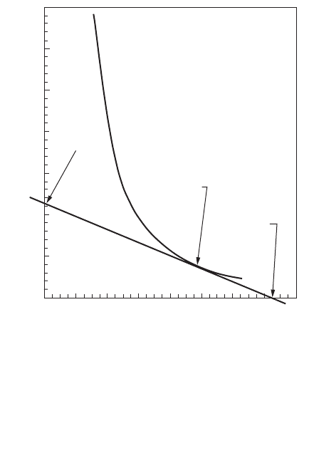
Kynch’s (1952) batch settling analysis is frequently employed. The movement of the interface is monitored
and plotted as in Fig. 9.10. The settling velocity of the interface is obviously the velocity of the particles
in it, and it can be calculated as the slope of the interface height-time plot:
(9.209)
where t = the sampling time (sec)
n
X
= the settling velocity of the particles (which are at concentration X) in the interface (m/s
or ft/sec)
z = the height of the interface at time t (m or ft)
z¢ = the height of the vertical intercept of the tangent line to the interface height-time plot
(m or ft)
Initially the slope is linear, and the calculated velocity is the velocity of the suspension’s initial con-
centration. As settling proceeds, the interface particle concentration increases, and its settling velocity
decreases, which is indicated by the gradual flattening of the interface/time plot. The interface concen-
tration at any time can be calculated from Kynch’s (1952) formula:
(9.210)
where X = the interface suspended solids concentration (kg/m
3
or lb/ft
3
)
X
0
= the initial, homogeneous suspended solids’ concentration (kg/m
3
or lb/ft
3
)
z
0
= the initial interface height and the liquid depth (m or ft)
v
zz
t
X
=
¢
-
X
Xz
z
oo
=
¢
© 2003 by CRC Press LLC
9-76 The Civil Engineering Handbook, Second Edition
Note that the elevation in the denominator is the intercept of the extrapolated tangent to the interface
height/time curve; it is not the elevation of the interface.
The batch flux for any specified solids concentration is as follows:
(9.211)
where F = the flux of solids settling through a horizontal plane in a batch container (kg/m
2
·s or lb/ft
2
·sec).
In the derivation of Eq. (9.210), Kynch shows that if the water is stationary, a concentration layer that
appears on the bottom of the settling column travels at a constant velocity upwards until it intersects
the interface. The concentration exists momentarily at the interface and then is replaced by another
higher concentration. Dick and Ewing (1967) reviewed earlier studies and concluded that there were
several deficiencies with the Kynch analysis, namely:
•Concentration layers do not travel at constant velocities, at least in clay suspensions.
•Stirring the bottom of a suspension increases the rate of subsidence of the interface.
•The Talmadge–Fitch (1955) procedure, which is an application of Kynch’s method for estimating
interface concentrations, underestimates the settling velocities at high sludge concentrations (Fitch,
1962; Alderton, 1963).
Vesilind (1974) recommends that this method not be used for designing thickeners for wastewater
sludges or for other highly compressible sludges.
Initial Settling Velocity Method
Most engineers prefer to prepare a series of dilutions of the sludge to be tested and to determine only
the initial settling velocity that occurs during the linear portion of the interface height/time curve. The
FIGURE 9.10 Typical interface height-time plot for hindered settling.
0
5
10
15
20
25
30
35
0246810121416
z'
z
Interface Height (cm)
t
tangent line
point of tangency
Elapsed Time (min)
FvX
X
=
© 2003 by CRC Press LLC
Physical Water and Wastewater Treatment Processes 9-77
resulting correlation between the initial settling velocities and the initial solids concentration can usually
be represented by the simple decaying exponential proposed by Duncan and Kawata (1968):
(9.212)
where a =a positive constant (units vary)
b =a positive constant (dimensionless)
X
0
= the initial suspended solids concentration in the column (kg/m
3
lb/ft
3
)
n
X0
= the settling velocity for a suspended solids’ concentration of X
0
(m/s or ft/sec)
The batch flux for each intial concentration is calculated using Eq. (9.211), and it is plotted versus the
suspended solids concentration. An example is shown in Fig. 9.11. This method assumes that the con-
centration in the interface is not changing as long as the height–time plot is linear, and by doing so, it
necessarily entails Kynch’s theory.
Thickener Design
Thickeners can conceptually be divided into three layers. On the top is a clear water zone in which free,
flocculent settling occurs. Below this is a sludge blanket. The upper portion of the sludge blanket is a
zone of hindered settling. The lower portion is a zone of compression. Many engineers believe that the
particles in the compression zone form a self-supporting lattice, which must be broken down by gentle
mixing. The compression zone may not exist in continuous flow thickeners.
Hindered Settling Zone
In free settling, the critical loading parameter is the hydraulic flow per unit plan area (e.g., m
3
/m
2
·s or
ft
3
/ft
2
·sec). In hindered settling, the critical loading parameter is the total solids flux, which is the solids
mass loading rate per unit area (e.g., kg/m
2
·s or lbm/ft
2
·sec). The result of a hindered settling analysis
is the required thickener cross-sectional area. The depth must be determined from a consideration of
the clarification and compression functions of the thickener.
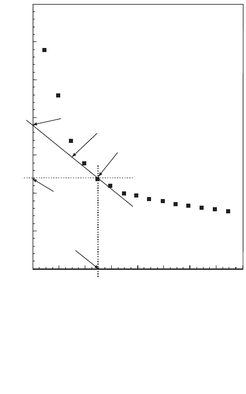
FIGURE 9.11 Yoshioka construction for the total flux.
Total
flux
Point of
tangency
Underflow
concentration
Total Suspended Solids Concentration (mg/L)
0 2000 4000 6000 8000 10000 12000 14000 16000
Flux (kg/sq m/day)
700
600
500
400
300
200
100
0
vaX
Xo
b
o
=
-
© 2003 by CRC Press LLC
9-78 The Civil Engineering Handbook, Second Edition
The total solids flux can be expressed three ways for an efficient thickener, each of which yields the
same numerical value. First, it is the total solids loading in the influent flow divided by the plan area of
the clarifier. For an activated sludge plant or a lime-soda plant with solids recycling, this would be
calculated as
(9.213)
where A = the thickener plan area (m
2
or ft
2
)
F
t
= the total solids flux (kg/m
2
·s or lb/ft
2
·sec)
Q = the design water or wastewater flow rate (m
3
/s or ft
3
/sec)
Q
r
= the recycle flow rate (m
3
/s or ft
3
/sec)
X
i
= the suspended solids’ concentration in the flow entering the thickener (kg/m
3
or lb/ft
3
)
Second, it can be calculated as the flux through the sludge blanket inside the thickener divided by the
plan area. In a continuous flow thickener, this consists of the flux due to the water movement through
the tank plus the flux due to the settling of particles through the moving water. If sludge is wasted from
the thickener underflow, the total water flow through the sludge blanket and in the underflow is Q
r
+ Q
w
:
(9.214)
where Q
w
= the waste sludge flow rate (m
3
/s or ft
3
/sec)
n
Xc
= the settling velocity at a suspended solids’ concentration X
c
(m/s or ft/sec)
X
c
= the suspended solids’ concentration in the sludge blanket in the thickener (kg/m
3
or lb/ft
3
)
Third, it is equal to the solids in the underflow divided by the tank area:
(9.215)
where X
u
= the suspended solids’ concentration in the clarifier underflow (kg/m
3
or lb/ft
3
).
Two design methods for continuous flow thickeners that are in common use are the Coe–Clevenger
(1916) procedure and the Yoshioka et al. (1957) graphical method. These procedures are mathematically
equivalent, but the Yoshioka method is easier to use.
The Yoshioka construction is shown in Fig. 9.11. First, the calculated batch fluxes are plotted against
their respective suspended solids concentrations. Then, the desired underflow concentration is chosen,
and a straight line is plotted (1) from the underflow concentration on the abscissa, (2) through a point
of tangency on the batch flux curve, and (3) to an intercept on the ordinate. The intercept on the ordinate
is the total flux that can be imposed on the thickener, F
t
. Equation (9.213), (9.214), or (9.215) is then
used to calculate the required plan area. Parker (1983) recommends that the peak hydraulic load rather
than the average hydraulic load be used in the calculation.
If the right-hand side of Eq. (9.214) is plotted for all possible values of X
c
, it will be found that F
t
is
the minimum of the function (Dick, 1970). Consequently, Eq. (9.212) may be used to eliminate n
Xc
from
Eq. (9.214), and the minimum of the total flux formula may be found by differentiating with respect to
X
c
(Dick and Young, no date):
(9.216)
F
QQX
A
t
ri
=
+
()
F
QQXvX
A
t
rwcXc
c
=
+
()
+
F
QQX
A
t
rwu
=
+
()
Fab
b
b
QQ
A
t
b
rw
bb
=-
()
[]
-
Ê
Ë
Á
ˆ
¯
˜
+
Ê
Ë
Á
ˆ
¯
˜
-
()
1
1
1
1
© 2003 by CRC Press LLC