Woodyard D. (ed.) Pounders Marine diesel engines and Gas Turbines
Подождите немного. Документ загружается.

running surface of the piston ring is chamfered on approximately half of the
surface. MAN Diesel explains that a well-running ring has a ballistic shape,
starting at the top of the ring and ending at its bottom. The chamfering therefore
helps the ring to run-in swiftly and safely as well as securing good gas sealing.
Mark 9 large bore engines 351
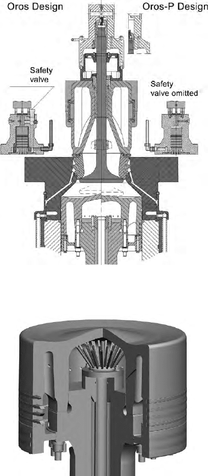
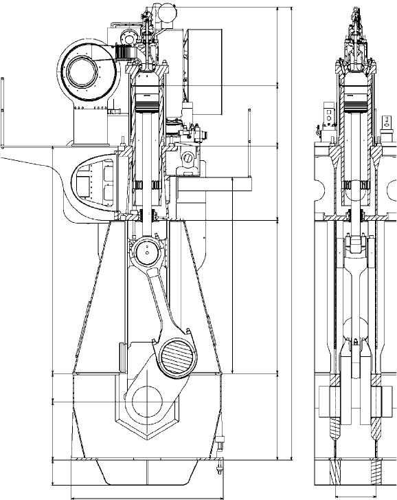
FigurE 10.44 The oros P relief bore design (right) is specied for the updated K-type
engines, omitting the safety valve on the exhaust valve actuator
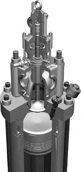
FigurE 10.45 A spray cooling insert secures a comfortably low piston temperature
for the Mark 9-rated large bore engines
352 MAN B&W Low-Speed Engines
PC rings are incorporated in the top of the liner to avoid the build-up of
carbon deposits on the topland, which would otherwise harm the cylinder con-
dition by scraping the lube oil off the walls. Overall, the combustion chamber
design is said to foster low wear rates at low cylinder oil feed rates, long TBOs
and good scuffing resistance.
With a view to omitting the safety valve on the exhaust valve actuator,
the Oros P version of the Oros design was chosen for the updated K-engines
(Figure 10.44). The reason was that the Oros piston leaves less room for fitting
the exhaust valve spindle than with the traditional piston design. To prevent
contact between piston and spindle, therefore, a mechanical stop is built into
the exhaust valve air spring, thus limiting the maximum spindle lift.
The exhaust valve design previously used for engines without an Oros com-
bustion chamber featured relief bores in the exhaust valve oil cylinder, which
would be uncovered in the event of excessive spindle lift. With the mechani-
cal lifter, however, excessive lift and pressure relief using such bores were no
longer possible; for that reason, a safety valve was built into the exhaust valve
actuator.
Using the Oros P version, designed with a slightly lower piston dome, cre-
ates enough space to allow a slightly larger exhaust valve spindle lift. This
makes it possible to exploit the well proven relief bore design of the exhaust
valve oil cylinder, and the safety valve on the actuator is no longer necessary.
MAN Diesel asserts that such a solution represents a cost saving for engine
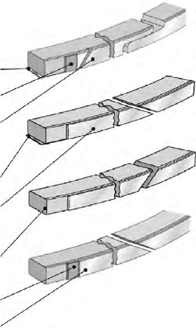
Alu-coat for running-In 0.1 mm
Grey cast iron base material
Cermet coating 0.3 mm
Grey cast iron base material
Chrome-plated bottom face
Grey cast iron base material
Alu-coating
Alu-coating
Alu-coating for running-In 0.1 mm
Cermet coating 0.5 mm
1st ring
2nd ring
3rd ring
4th ring
Vermicular cast iron base material
Chrome-plated bottom face
FigurE 10.46 Hard-Coated/semi Alu-coat ring package
licensees and a simplification for operators, yet with performance identical to
the original Oros design.
A spray cooling insert is now provided to obtain a comfortably low piston
temperature (Figure 10.45). Improved cooling is confirmed by piston crown
temperature measurements taken on the testbed and on engines in service.
Comparative measurements with and without a spray cooling insert revealed a
temperature reduction at the central part of the crown, both on the combustion
chamber side and on the cooling side; the insert thus increases both of the mar-
gins against hot corrosion and underside coke formation.
An exhaust valve unit of a modified type uses a low-grade cast iron hous-
ing with water cooling around the spindle guide and bore-cooled twin stud
bosses. The upper part of the housing forms the bottom of the air spring and
the lower part forms part of the cooling chamber in the cylinder cover. Apart
from eliminating cold corrosion of the exhaust valve duct, the lower cooling
intensity slightly increases the exhaust gas energy, thus improving the potential
for waste heat recovery.
A W-seat of low height is used and a high spindle guide lubricated by the
controlled oil level system is being introduced. The system implies a minimum
oil level inside the air cylinder, secured by a high outlet (overflow) to the safety
valve. This ensures a level high enough to have oil on the top of the sealing
ring, the oil passing through three bores in the flange. Furthermore, the safety
valve adjustment corresponds to this high oil level. No sealing air arrangement
or special type of sealing ring is required by this design, which means that the
old type ring can be used regardless of the type of valve spindle.
Modifications to the ME electronic control system reflected experience
gained from engines in service. Improvements have benefited the hydraulic
servo oil supply, for which there are now two standards: engine driven and
electrically driven.
Engine-driven oil supply. The well proven design with a chain-driven
gearbox, which drives three to five high-pressure pumps, was selected for the
updated engines. A chain is particularly preferred on large bore engines because
of its reliability, easy installation and high tolerance against relative movements
of the crankshaft. Furthermore, the chain is used for driving the second-order
moment compensator on six-cylinder engines specified with such attachments.
Compared with the initial ME/ME-C large bore engine assembly, however,
the new design has been simplified. It comprises small accumulator blocks (one
for each pump) and a safety block positioned on the aftmost HCU. The large
double-walled supply pipe with forged connection pipes was replaced by stand-
ardized high-pressure pipes. Easing installation and avoiding vibrations from the
pumps, high-pressure hoses were installed between the pumps and HP pipes.
Electrically driven oil supply. If this arrangement is preferred, the complete
gearbox and chain drive are replaced by electrically powered HP pumps, which
are similar to the mechanical pumps. The chain drive section of the framebox
is omitted, thus making the engine structurally simpler than an engine with a
mechanical servo oil supply.
Mark 9 large bore engines 353
354 MAN B&W Low-Speed Engines
ME-B Engines
Electronically controlled fuel injection was extended to smaller bore MAN
B&W two-stroke engines in mid-2006 with the launch of the ME-B series,
initially comprising 350-mm and 400-mm-bore models but later extended to
embrace 460-mm, 500-mm and 600-mm-bore versions (Figures 10.48–10.50).
These S35, 40, 46, 50 and 60ME-B designs cover a power band from 4350 kW
to 19 040 kW and are marketed in parallel with their established mechanical
MC counterparts, which may be favoured by some shipyards and ship owners
in the targeted propulsion sectors.
Development was driven by a perceived market requirement for the low-
est possible propeller speed in relation to bore size, leading to a stroke–bore
ratio of over 4.4:1 for the S35, S40 and S50 designs (similar to that of MAN
Diesel’s 4T50ME-X research engine). The 46 and 60-bore models have slightly
lower ratios of 4.2 and 4:1, respectively. Type approval tests for the first pro-
duction engine, a six-cylinder S40ME-B version, were completed in December
2007, since when models of all bore sizes have flowed into service.
It was decided at an early stage of development to retain a slim camshaft
for controlling the exhaust valves, thereby also reducing the required capacity
of the electronic control system. While this small camshaft operates the valves
mechanically in the traditional manner, an electronically controlled fuel injection
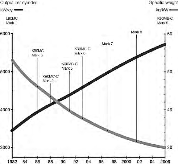
FigurE 10.47 Trends in output per cylinder and specic weight for MAN B&W
90-bore engines from Mark 1 to Mark 9 status
system adapted from ME practice enables the ME-B engines to meet IMO Tier
II emission requirements.
Fuel injection is performed by one fuel booster per cylinder, similar to
the established system for larger bore ME engines. The pressure boosters are
mounted on HCU—two boosters per unit—with hydraulic oil supplied to the
HCUs via a single oil pipe enclosed in the camshaft housing. In addition to two
pressure boosters, the HCU is equipped with two ELFI valves and two Alpha
Lubricators. The accumulators used in the HCUs of the established ME engine
design are replaced by one buffer of hydraulic oil serving each HCU, which in
turn serves the injection needs of two cylinders.
ME-B engines 355
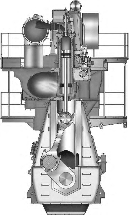
FigurE 10.48 Cross-section of S50ME-B engine
356 MAN B&W Low-Speed Engines
Compression of the oil with respect to its bulk modulus accounts for the
accumulator effect. The hydraulic system pressure is 300 bar (increased from
the 250 bar of the standard ME system). The higher pressure makes it possible
to omit the accumulators normally installed on the HCU; instead, a hydraulic
volume for each of the two cylinders is placed below the HCU inside the cam-
shaft housing. Two electrically driven pumps installed at the front end of the
engine provide hydraulic power for the injection system. In the event of failure
of one pump, more than 50 per cent engine power will remain available, ena-
bling 80 per cent ship speed to be maintained.
The ME-B fuel injection system offers the same possibility for rate shaping as
the established ME engines. Injection is controlled by a proportional valve allow-
ing continuous change of the injection pressure; typically, a gradual pressure
410 950 460 3710
3200
1405 2500
7376
1210 980 1270
2580
700
FigurE 10.49 Cross-sections of S40ME-B engine
increase during injection is desirable. Specific fuel consumption, as well as
emissions, is influenced by the injection profile. One profile is often favourable
for sfc but at the cost of high NOx emissions, while the opposite effects result
from another profile. The freedom to choose the fuel injection profile is thus a
valuable tool in minimizing sfc while keeping emissions within given limits.
Fuel valves similar to those of S35MC and S42MC engines are used for the
S35/40ME-B models, the fuel nozzles being of the proven slide type already
introduced as standard on all small bore engines.
The engine control system uses the same multi-purpose controllers (MPCs) as
the traditional ME control system. One MPC can control injection on two cylin-
ders, but one of the MPCs also controls the hydraulic pressure and therefore only
controls injection on one cylinder. A six-cylinder ME engine requires 13 MPCs,
while a corresponding small bore ME-B model may need only four MPCs.
ME-B engines 357
FigurE 10.50 ME-B engine combustion chamber
358 MAN B&W Low-Speed Engines
Most of the design concepts of the large bore Mark 9 engines are shared
by the ME-B series, including a piston with high topland, PC ring, twin stay
bolts, thin shell bearings, low friction guide shoes and thrust cams. The struc-
tural parts of the S35/40ME-B engines were designed to secure the rigid-
ity and strength required for the higher output. The bedplate is of welded
design, but the normal cast part for the main bearing girders is made from
rolled steel plates. The aim was to achieve homogeneity of the material used
for that bearing area with no risk of casting imperfections arising during final
machining.
A new main bearing concept was under development at the launch of the
engines to decrease the production cost of the bedplate. In the new design,
the bedplate and bearing caps are finish machined as separate parts, with the
caps positioned by means of the bearing shell and kept in position with the
force from hydraulically tightened studs and high-friction coated shims placed
between bearing cap and bedplate. The proven main bearing design used on all
MAN B&W small bore engine designs, however, was to be retained until the
new development was completed.
A framebox of the proven triangular guide plane design with twin stay-
bolts—now standard on all updated MAN B&W engine types—was specified
to provide excellent support for the guide shoe forces.
Two possibilities are available for the cylinder frame—nodular cast iron
(KF) or a welded design with integrated scavenge air receiver—but it was
decided to use the cast solution because of the material’s high strength and
high E-modulus in countering the high ignition force. Furthermore, compared
with C3Cu material, the weight of a six-cylinder S35ME-B cylinder frame can
be reduced by 3 tonnes, corresponding to a 12 per cent cost reduction for the
frame.
A semi-built crankshaft, in one piece, is made of S34CrNi or S42Cr1 mate-
rial. Even though the stroke–bore ratio was raised for the new engines, the
cylinder distance is only slightly increased. Comprehensive FEM calculations
were performed to ensure that the geometry (including the journal diameters)
of the shaft was optimized for maintaining the rigidity, shrink-fit and stresses at
the same level as for the MC-C engines.
Based on the design introduced for the MC-C engine, the thrust bearing
is very compact. Addressing the increased propeller thrust resulting from the
higher engine power, a flexible thrust cam secures a more even force distribu-
tion on the pads. The overall dimension of the parts can thus be smaller than
that with the old design.
A connecting rod design based on that applied throughout the small bore
engine programme (initially introduced for the L35MC model) is used. To
reduce the production cost and oscillating forces, however, the new design is a
combination of those used in the MC-C and 35MC engines. The crosshead pin
design is taken from the S50MC-C engine, with the bearing dimensions based
on long experience with the S35MC engine (exploiting a hardened running sur-
face for the pin). The guide shoe is of the new low friction design.
Bearings are of the same thin-shell design as for the previous small bore
engine generation, the material on all large bearings being Sn40Al. The rela-
tive loads on the large bearings are in all cases below the design targets.
The increased power of the ME-B engines dictated careful investigation
of the combustion chamber to compensate for the higher ignition pressure and
thermal load, and also to raise the reliability of the components and further
extend the TBOs (Figure 10.50).
A slim cylinder liner used for other small bore MC-C/ME engines was also
applicable to the ME-B 35 and 40-bore types, but the material was upgraded
to Tarkalloy A to counteract the higher ignition pressure. A PC ring was also
introduced to prevent bore polish.
The bore-cooled piston has a semi-high topland and a crown shaped in
conjunction with the combustion chamber to cope with the increased power.
Extensive FEM calculations were carried out in evolving the crown geometry
to enable the high firing pressure and mean pressure to be withstood. A piston
ring pack similar to those used for the established small bore engines features a
No. 1 ring with high CPR and Nos. 2 to 4 rings with angle cut. All of the rings
have an Al-coat on the running surface for safe running-in. If a prolonged TBO
is requested, a special ring pack with hard coating on the running surfaces of
No. 1 ring can be specified as an option.
As with the larger bore ME engines, an Alpha Lubricator is standard for
the ME-B models, bringing the benefits of an ACC lubrication mode to smaller
bore designs: a low total cylinder lube oil consumption while maintaining an
excellent cylinder condition.
ME-B engines 359
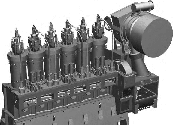
FigurE 10.51 An ME-B engine showing the camshaft-activated exhaust valve
system and HCus serving two cylinders
360 MAN B&W Low-Speed Engines
Exhaust valves are actuated by a light camshaft (small diameter and small
exhaust cam) driven by a chain located at the aft end of the engine; the chain
size is smaller than the MC type chains ((Figure 10.51). Pursuing common. Pursuing common
spare parts for all four engines, the exhaust valves used for the S35ME-B and
S40ME-B models are the same as those for the S35MC and S42MC models,
respectively. The DuraSpindle design has a W-seat bottom piece.
Appropriate turbocharger models from MAN Diesel, ABB and Mitsubishi
can be specified for the ME-B engines. The turbocharger can be aft mounted,
as for the existing engines, or exhaust side mounted. The latest type of water
mist catcher and water drain arrangement were adopted. MAN Diesel’s TCA
turbochargers with variable nozzle ring technology (see Chapter 7) are option-
ally available, compensating (in terms of part-load fuel consumption) for the
absence of variable exhaust gas valve timing.
An auxiliary blower of the new integrated type, introduced on the Mark 8
version of the S50MC-C engine, yields a cost reduction of around 40 per cent
over the existing design. Maintenance is also lowered as the belt drive is omit-
ted for the integrated blowers.
See Chapter 9 for more details of MAN Diesel’s Intelligent Engine
development.