Woodyard D. (ed.) Pounders Marine diesel engines and Gas Turbines
Подождите немного. Документ загружается.

temperatures, and the low ports give a longer effective expansion stroke in the
cycle (Figure 12.23).
The RTA84T-B engine was uprated at the end of 1998 from 3880 kW/cyl-
inder at 74 rev/min to 4100 kW/cylinder at 76 rev/min to create the Version
D through tuning and turbocharging matching measures. The power avail-
able from a seven-cylinder engine was thereby increased from 27 160 kW to
28 700 kW, better addressing the propulsive demands of VLCCs with higher
service speeds. Nine-cylinder RTA84T-D models, each developing 36 900 kW,
were specified to power a series of 442 500 dwt tankers with a service speed of
16.5 knots.
rTA design developments 411
with VIT/VEC/IPDLC
without VIT/VEC/IPDLC
140
130
120
110
100
90
80
70
60
50
40
t Valve centre
Engine speed
Load
BSFC
Temperatures
before turbine b.T.
after turbine a.T.
t Liner at TDC
Top-ring
45 50 55 60 65 70 75 min
–1
25 50 65 75 90 100 %
P
comp
Smoke
BSFC
135
130
125
120
(g/kW h) (g/bhp h)
450
400
350
300
250
(C)
350
300
250
t Valve seat
Max. cylinder pressure pz
Compression pressure pc
(%)
10
5
0
Smoke
(C)
240
220
200
180
160
140
(C)
600
550
500
P
cyl.
t Valve centre
t Valve seat
t Liner at TDC
t after Turbine
(bar)
t before Turbine
(C)
180
170
160
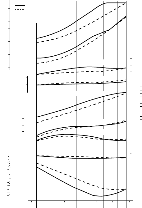
FigurE 12.21 inuence of the viT/vEC combination (solid line) compared with
results without viT/vEC (dashed line) on the performance characteristics of a
7rTA84T engine. The engine has an ri rating of 27 160 kW at 74 rev/min and exploits
an exhaust gas power turbine
412 Wärtsilä (Sulzer) Low-Speed Engines
Structural, running gear, combustion chamber, fuel injection, turbocharging
and scavenge air system design details are similar to those of the RTA84C and
RTA96C engines described later. The large stroke-to-bore ratio of the RTA84T,
however, allows a relatively deeper combustion chamber with more freedom
in the layout of the fuel spray pattern. The semi-built crankshaft had to cater
for the longest stroke ever applied in a Sulzer engine; to limit the crankshaft
weight for production, assembly and transport, the main journals and crankpins
are bored. The design of the crank has a good transverse width at the upper
part of the web, allowing the latter to be slim longitudinally.
The favourable torsional vibration characteristics allow six-cylinder engines
to use a viscous damper in many cases instead of a Geislinger damper.
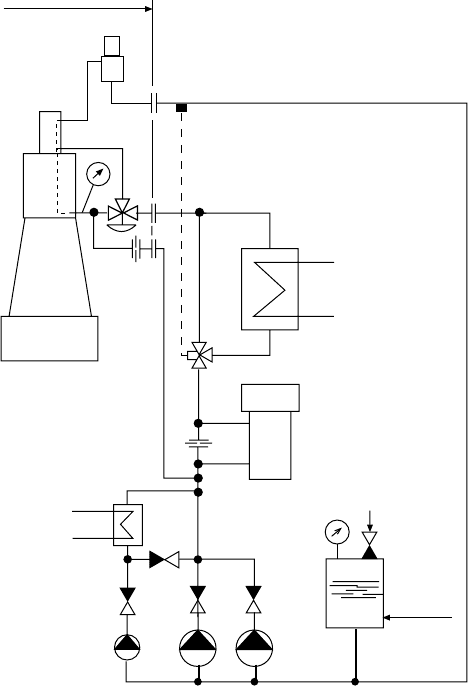
Preheating pump
Expansion tank
Water
suppy
Compressed
air
Fresh-water
generator
Cooler
Preheater
RTA84T
Main & standby
circulating pumps
Engine
supply
FigurE 12.22 Schematic layout of the rTA84T cylinder jacket cooling water system
with a load-dependent controlled bypass past the jacket to the cylinder cover
RTA84T-B and RTA84T-D engine data
RTA84T-D RTA84T-B
Bore (mm) 840 840
Stroke (mm) 3150 3150
Stroke–bore ratio 3.75 3.75
power (mcr) (kW/cyl) 4100 3880
Cylinders 5–9 5–9
Speed range (rev/min) 61–76 59–74
Mean eective pressure (bar) 18.5 18
Mean piston speed (m/s) 8 7.77
Maximum cylinder pressure (bar) 144 140
Specic fuel consumption (g/kW h) 160–168 160–168
rTA design developments 413
0°C
300
200
0°C
300
400
500
300
200
°C
100
200
100 200 300 °C
TDC-
Top ring
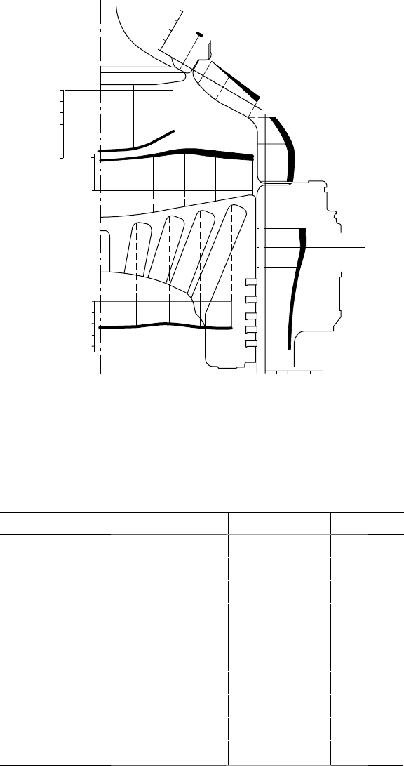
FigurE 12.23 Surface temperatures measured on the combustion chamber compo-
nents of the rTA84T-B engine at full load r1 rating. The thickness of the lines repre-
sents the circumferential variation in temperature

414 Wärtsilä (Sulzer) Low-Speed Engines
rTA68T-B Engine
A further development of the RTA-T programme resulted in the 680-mm bore
RTA68T-B engine, the first example of which entered service in November
2000. The design benefited from all the reliability improvements incorporated
in the earlier RTA-T engines, with parameters similar to those of the smaller
bore RTA48T-B and RTA58T-B models. TriboPack design measures (see later)
contributed to piston-running behaviour, and a new design of piston rod gland
featured oil scraper rings with grey cast iron lips: the system oil is fully recir-
culated and a dry neutral space effected.
RTA68T-B engine data
Bore
680 mm
Stroke 2720 mm
Stroke–bore ratio 4
power (mcr) 2940 kW/cyl
Cylinders 5–8
Speed range
75–94 rev/min
Mean eective pressure 19 bar
Mean piston speed 8.5 m/s
Maximum cylinder pressure 150 bar
Specic fuel consumption 161–169 g/kW h
rTA84C and rTA96C Engines
Introduced in September 1988 for propelling the coming generation of larger
and faster container ships, the RTA84C engine was developed from the RTA84,
already established in that market. In 1993 its power output was increased by 6
per cent, the cylinder cover modified and the number of fuel nozzles increased
from two to three; these measures contributed to a reduction in the thermal
load of the combustion chamber. The performance of the series, shown in the
following table, equated to a maximum output of 48 600 kW at 102 rev/min
from the 12-cylinder model.
RTA84C engine data
Bore
840 mm
Stroke 2400 mm
Stroke–bore ratio 2.86
power (mcr) 4050 kW/cyl
Cylinders 6–12
Speed range 82–102 rev/min
Mean eective pressure 17.9 bar
Mean piston speed 8.2 m/s
Maximum cylinder pressure 140 bar
Specic fuel consumption 166–171 g/kW h
Increasing sizes of post-Panamax container ships dictated more powerful
engines and stimulated the introduction of the RTA96C series in December
1994. The 960-mm bore design was fully based on the RTA84C (Figures 12.24
and 12.25), which it supplemented and later replaced in the programme. The
RTA84C series was further superseded by the launch at end-2005 of the 82-bore
design (see p. 437).
The selection of a stroke (2500 mm) some 100 mm longer than that of the
RTA84C engine for the RTA96C design (Figure 12.26) was influenced by
demands for the highest reliability. By adopting a longer stroke, the absolute
depth of the combustion chamber could be proportionally increased to give
more room for securing the best combustion and fuel injection parameters,
and better control of temperatures in the combustion chamber components.
Additionally, the slightly longer stroke fosters a simplified crankshaft design
with enhanced reliability, since the shrunk-in main journals do not cut the jour-
nal fillets at the inner sides of the crank webs.
A TBO of 3 years from the RTA96C engine’s key components was sought,
a goal underwritten by a cast iron (preferably die cast) cylinder liner with the
necessary amount of wear-resistant hard-phase particles and a smoothly machined
rTA design developments 415
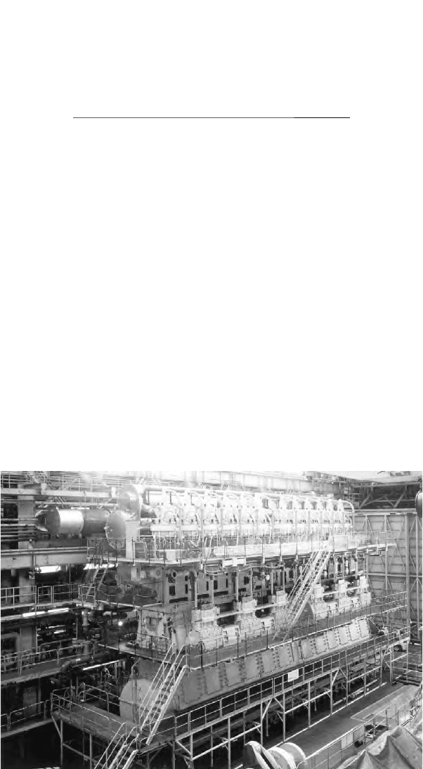
FigurE 12.24 A 12-cylinder rTA84C engine on test
416 Wärtsilä (Sulzer) Low-Speed Engines
and honed surface for quick and trouble-free running-in; bore cooling of all the
main combustion chamber components; three fuel injection valves symmetrically
distributed in the cylinder cover to contribute to evenness of temperature distribu-
tion; cylinder oil lubrication of the liner surface via two levels of quills to achieve
effective and economical distribution; and a top piston ring pre-profiled and
plasma coated to secure the lowest wear rate to reach the 3-year TBO goal with
sufficient margin. Diametral cylinder liner wear rates of around 0.03 mm/1000 h
are reported for the RTA96C design, in service. All new engines further benefit
from TriboPack measures to enhance piston-running behaviour (see p. 423).
The semi-built crankshaft comprises combined crankpin/web elements forged
from a solid ingot, with the journal pins then shrunk into the crank web. The main
bearings have white-metal shells, and the main bearing caps are held down by a
pair of jack bolts in the RTA84C and by a pair of elastic holding-down studs in the
RTA96C. The crosshead bearing is designed to the same principles as for all other
RTA engines; it also features a full-width lower half bearing. The crosshead bear-
ings have thin-walled shells of white metal to yield a high load-bearing capacity.
Wärtsilä low-speed engines retain a separate elevated-pressure lube oil supply to
the crosshead; this provides hydrostatic lubrication, which lifts the crosshead pin
off the shell during every revolution to ensure that sufficient oil film thickness is
maintained under the gas load: crucial to long-term bearing security.
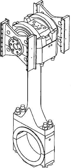
FigurE 12.25 Crosshead and connecting rod assembly for rTA84C engine
The combustion chamber was recognized as the most important design area
because of its key influence on engine reliability and the high power concentra-
tion. Component design was based on established practice and benefited from
work carried out for the medium-bore RTA48T and RTA58T engines. Wärtsilä
suggests that bore-cooling technology provides an escape from the rule that
larger components (resulting from a larger bore) when subjected to thermal
loading will also have higher thermal strains. With bore cooling, the thermal
strains in the cylinder cover, liner and piston crown of the RTA96C can be
kept fully within the values of earlier generations of RTA engines, as can the
mechanical stresses in those components.
rTA design developments 417
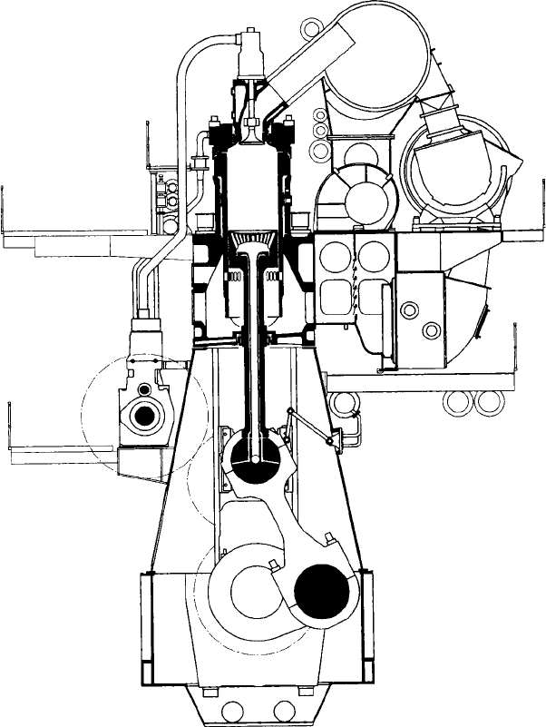
FigurE 12.26 Cross-section of rTA96C engine, designed for propelling ultra-large
container ships
418 Wärtsilä (Sulzer) Low-Speed Engines
The solid forged steel, bore-cooled cylinder cover is secured by eight elas-
tic studs, and the central exhaust valve of Nimonic 80A material is housed in a
bolted-on valve cage. Anti-corrosion cladding is applied to the cylinder covers
downstream of the injection nozzles to protect the covers from hot corrosive or
erosive attack. The pistons feature a forged steel crown with a short skirt; the
crown is cooled by combined jet-shaker oil cooling achieving moderate tem-
peratures on the crown and a fairly even temperature distribution across the
crown surface. No coatings are necessary.
A high structural rigidity with low stresses and high stiffness is important for
low-speed engines. The RTA84C and RTA96C designs exploit a well-proven struc-
ture with a ‘gondola’ type bedplate surmounted by very rigid A-shaped double-
walled columns and cylinder blocks, all secured by pre-tensioned vertical tie
rods. Both bedplate and columns are welded fabrications designed for minimum
machining. The cylinder jacket is assembled from individual cast iron cylinder
blocks bolted together to form a rigid whole. The fuel pumps are carried on sup-
ports on one side of the column and the scavenge air receiver on the other side of
the cylinder jacket.
Access to the piston under-side is normally from the fuel pump side but is also
possible from the receiver side of the engine, to facilitate maintenance of the pis-
ton rod gland and also for inspecting piston rings. The tilting-pad thrust bearing is
integrated in the bedplate. The use of gear wheels for the camshaft drive allows the
thrust bearing to be very short and stiff, and to be carried in a closed rigid housing.
The three uncooled fuel injection valves in each cylinder cover have nozzle
tips sufficiently long for the cap nut to be shielded by the cylinder cover and
not exposed to the combustion space. The camshaft-driven fuel injection pumps
are of the double-valve controlled type, traditional in Sulzer low-speed engines.
Injection timing is controlled by separate suction and spill valves regulated
through eccentrics on hydraulically actuated lay shafts. Flexibility in timing is
possible through the VIT system for improved part-load consumption, while the
FQS lever can adjust timing according to the fuel oil quality. The valve-controlled
fuel injection pump, in comparison with a helix type, has a plunger with a signifi-
cantly greater sealing length. The higher volumetric efficiency reduces the torque in
the camshaft; additionally, injection from a valve-controlled pump is far more
stable at very low loads, and rotational shaft speeds down to 15 per cent of the
rated speed are achieved. Valve control also has the benefits of less deterioration
of timing over the years owing to reduced wear and freedom from cavitation.
The camshaft is assembled from a number of segments, one for each fuel
pump housing. The segments are connected through SKF sleeve couplings,
each segment having an integral hydraulic reversing servomotor located within
the pump housing. The camshaft drive is a traditional Sulzer arrangement,
effected in this case by three gearwheels housed in a double column located
at the driving end or in the centre of the engine. The main gearwheel on the
crankshaft is in one piece and flange mounted.
Scavenge air is delivered by a constant pressure turbocharging system based on
one or more turbochargers, depending on the number of engine cylinders. For start-
ing and during slow running, scavenge air delivery is augmented by electrically
driven auxiliary blowers. The scavenge air receiver incorporates non-return flaps,
an air cooler and the auxiliary blowers; the turbochargers are mounted on the
receiver, which also carries the fixed foot for the exhaust manifold. Immediately
after the cooler, the scavenge air passes through a water separator comprising a row
of vanes that divert the airflow and collect the water. Ample drainage is provided to
completely remove the condensed water collected at the bottom of the air cooler
and separator. Effective separation of condensed water from the stream of scavenge
air is thus accomplished, a necessity for satisfactory piston-running behaviour.
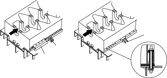
RTA engines have simple seating arrangements with a modest number of
holding-down bolts and side stoppers (14 side stoppers are needed for a 12-
cylinder RTA96C engine). No end stoppers or thrust brackets are needed as thrust
transmission is provided by fitted bolts or thrust sleeves applied to a number of
the holding-down bolts (Figure 12.27). The holes in the tanktop for the thrust
sleeves can be made by drilling or even flame cutting. After alignment of the
bedplate, epoxy resin chocking material is poured around the sleeves. The engine
is equipped with an integrated axial detuner at the free end of the crankshaft, and
a detuner monitoring system developed by Wärtsilä is standard equipment.
rTA96C uprating and programme Expansion
The first RTA96C engine, an 11-cylinder model, started tests in March 1997
and was followed into service by eight-, nine- and ten-cylinder models and
numerous twelve-cylinder versions. The design was originally offered with an
output of 5490 kW/cylinder and up to 12 cylinders, but the rating was increased
by 4 per cent in the year 2000 to 5720 kW/cylinder at 102 rev/min (see the fol-
lowing table). At the same time, the programme was extended to embrace an
in-line 14-cylinder model delivering 80 080 kW (the first time such a low-speed
engine configuration had featured in a production programme) and suitable for
powering single-screw post-Panamax container ships with capacities of 10 000
TEU-plus and service speeds of up to 25 knots (Figure 12.28).
The first-ever 14-cylinder low-speed engines (RT-flex96C models) were
ordered in early 2005 to provide a series of 8600 TEU container ships with
a service speed of 27 knots. The original RT-flex96C crankshaft had sufficient
rTA design developments 419
Thrust Thrust
Thrust bracket
Side stopper
Side stoppe
r
FigurE 12.27 Arrangements for transmitting propeller thrust to the rTA84T, rTA84C
and rTA96C engine seatings; the inset shows the thrust sleeve for the thrust bolts
420 Wärtsilä (Sulzer) Low-Speed Engines
208.5
*min.637 1194.5 2215.5 *min.500
3150
3150
2950
(13000)
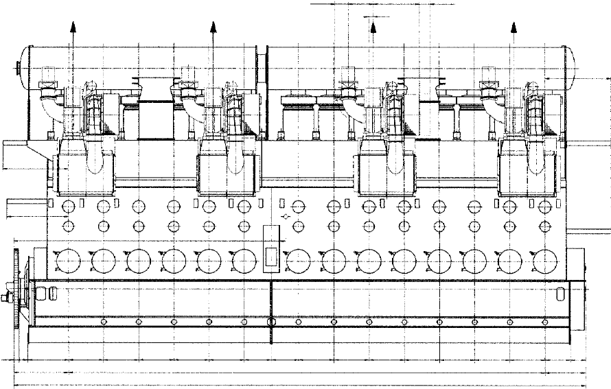
1 2 3 4 5 6 7 8 9 10 11 12 13 14
265 411 1944 1680 1680 1680 1680 1680 1295 1295 1680 1680 1680 1680 1680 1680 1680 1220 723
2620
22750
1943
27313
FigurE 12.28 Side elevation of a 14-cylinder rTA96C engine