Woodyard D. (ed.) Pounders Marine diesel engines and Gas Turbines
Подождите немного. Документ загружается.

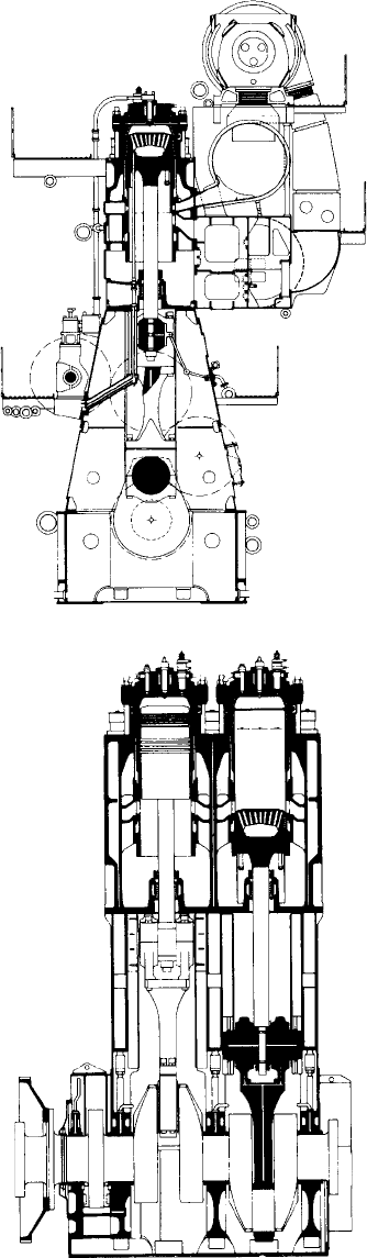
FigurE 12.39 Cross-section of 900-mm bore Sulzer rLB90 engine
FigurE 12.40 Longitudinal section of rLB90 engine
442 Wärtsilä (Sulzer) Low-Speed Engines
Bedplate with Thrust Block
For the RL-type engine bedplate, a new concept of great simplicity was
applied. Both the cross girders and the longitudinal structure are of single-wall
fabricated design giving very good accessibility for the welded joints. The cen-
tral bearing saddles are made of cast steel and only one row of mounting bolts
on each side is used to secure the bedplate to the ship’s structure.
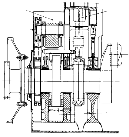
The completely new design feature was the method of integrating the thrust
block into the bedplate (Figure 12.41) allowing an extremely compact design and
saving engine length. The first crankshaft bearing on the driving end is a combined
radial–axial bearing. The bedplate is a one-piece structure for all engines from four
to eight cylinders, but, if required, it can be bolted together from two halves.
Thick-walled white-metal-lined bearing shells are used to support the
crankshaft and guarantee an optimum safety for the running of the crankshaft.
Crankshaft
In addition to the traditional semi-built-type crankshaft, a monobloc continu-
ous grain flow forged type can be used. From four to eight cylinders, the crank-
shaft is a one-piece component with an integrated thrust collar section. Only
one journal and pin diameter was used for all engines up to eight cylinders. For
RLA engines larger than the RLA56, the crankshaft was semi-built, and the
thrust shaft separately bolted to the crankshaft.
Engine Frame
For the small RLA56 engine, a new method of frame construction was
used. Cast iron central pieces, on which the crosshead guides are bolted, are
Camshaft
driving gear
Thrust bearing
Lanchester
balancer
FigurE 12.41 integrated thrust bearing and camshaft drive for rL engine
sandwiched between two one-piece fabricated side-frame girders. This replaced
the traditional construction of ‘A’ frame bolted to the bedplate with side plates
attached with access doors forming the enclosure. Larger RL-type engines use
‘A’ shaped columns of fabricated double wall design, assembled with longitu-
dinal stiffening plates to constitute a rigid structure between the bedplate and
cylinder blocks (Figures 12.42 and 12.43).
Sulzer rL-type engines 443
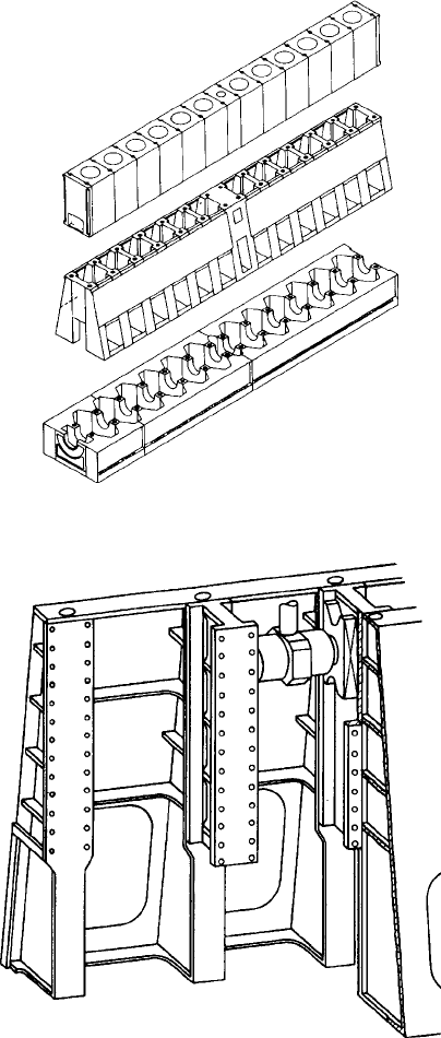
FigurE 12.42 Structural arrangement of bedplate, columns and cylinder jackets for
12-cylinder Sulzer rL engine
FigurE 12.43 Arrangement of columns for rLA56 engine
444 Wärtsilä (Sulzer) Low-Speed Engines
Cylinder Jackets
The cylinder jackets are made of fine lamellar cast iron produced as single
block units bolted together in the longitudinal plane to form a single rigid
unit, and held on top of the frame section by long tie bolts secured in the bed-
plate. For the small RLA56 engine, multi-cylinder blocks consisting of two or
three cylinders were standard and provide great rigidity of the structure. The
arrangement of the cooling water passages in the jackets ensures forced water
circulation and optimal water distribution around the exhaust canal.
Because of the steadily rising charge air pressures, the design of the
air receiver was modified to allow the use of automatic welding techniques.
Instead of a rib-stiffened plain side plate, a semi-circular pressure containment
was fitted with an integral air inlet casing. The auxiliary blower is mounted on
the front end of the receiver, thus eliminating inclined ducts.
Combustion Chamber Components
The combustion chamber of RL-type engines is principally of the same shape
as that of the RND-M. The cylinder cover is basically a one-piece steel block
with cooling bores, while an identical arrangement of bore cooling is applied
to the upper collar of the cylinder liner, which is made from lamellar cast iron,
a material of good heat conductivity and wear resistance. Figure 12.44 shows
the arrangement with cover, cylinder liner and piston.
A new type of piston crown was introduced for the RL series engines. This
combustion chamber component similarly uses a bore cooling arrangement
(Figures 12.45 and 12.46) as previously only applied to the liner and cover.
Water cooling was retained but the piston bore cooling uses a somewhat differ-
ent mechanism to the force flow system of the liner and cover.
The cooling space of the piston crown is approximately half filled with
cooling water, and, as a result of piston acceleration and deceleration, a ‘cock-
tail shaker’ effect is produced to provide excellent heat removal. This effect is
capable of ensuring efficient heat transfer under all prevailing load conditions
in order to keep the vital temperatures on the piston crown and around the pis-
ton rings within suitable limits.
As a result of this new design, the crown temperatures were lowered com-
pared with the previous construction. Forged steel blocks were specified for
piston crown manufacture but cast steel versions were also used.
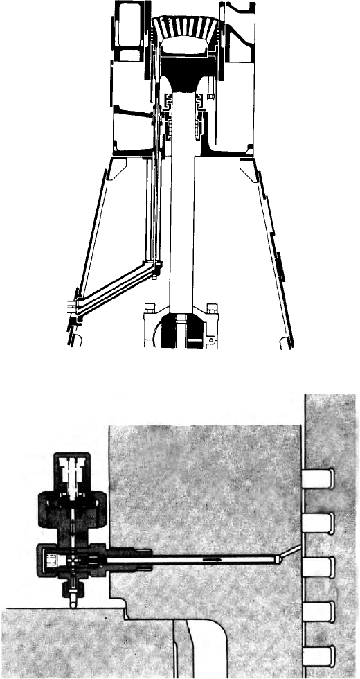
Cylinder Lubrication
Lubrication of the cylinder is through six quills mounted in the upper area of
the liner just above the cylinder jacket, as shown in Figure 12.47. The oil dis-
tribution grooves have a very small angle of inclination to avoid blow-by over
the piston rings and small but regular quantities of cylinder oil supplied by an
accumulator system. Two further lubrication points are provided below the
scavenge ports on the exhaust side with the necessary oil pumps positioned on
the front side of the engine above the camshaft drive.
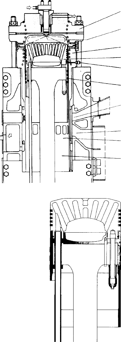
FigurE 12.44 Combustion chamber components for rLA90 engine
Bore-cooled cylinder
cover with 8 studs
Fuel nozzle with
increased service life
Bore-cooled cylinder line
r
Bore-cooled piston head
Accumulator cylinder
lubrication, 8 lubricating
points
Four bronze bands
Exhaust ports
Inlet ports
Two lubricating points
below ports
Honed running surface
of lower liner parts
FigurE 12.45 detail view of rL engine piston with bore cooling
446 Wärtsilä (Sulzer) Low-Speed Engines
Crosshead design
The crosshead is similar to that used for RND engines and has double guided
slippers. The pin size was increased for safety and thin-walled half shells of the
FigurE 12.46 Arrangement of telescopic pipes for rL engine piston cooling
FigurE 12.47 Cylinder lubricator for rL engine
aluminium–tin type were used. The pin itself is of forged homogeneous steel of
symmetrical design and can therefore be turned around in case of damage. The
piston rod is connected to the pin by a single hydraulically tightened nut, while
the slippers, made of cast steel and lined with white metal, are bolted to the ends
of the pin. The cast iron double guide faces are fitted to the engine columns.
The connecting rods of traditional marine type have a forged normalized
steel bottom end bearing, lined with white metal, held in place by four hydrau-
lically tensioned bolts. Compression shims are provided between the bottom
end bearing and the palm of the connecting rod.
piston Assembly
The piston (Figure 12.45) consists of a water-cooled cast steel crown, a cast
iron skirt with copper bandages and a forged steel piston rod, with the piston
rings fitted in chromium-plated grooves.
The water-cooled piston has proved very reliable when running on heavy
fuels, and the use of water cooling has resulted in practically negligible sys-
tem oil consumption. (With oil cooling, oil is consumed usually as a result of
thermal ageing on hot piston walls. Oil leaks from oil-cooled pistons may also
occur on other engine types.) The two-part gland seals for the piston rod, and
telescopic piston cooling pipes can be inspected while the engine is running
and can be dismantled without removing the piston. The double-gland dia-
phragm around the piston rod completely separates the crankcase from the pis-
ton undersides, preventing contamination of the crankcase oil by combustion
residues or possible cooling water leakages. In addition, the freshwater piston
cooling water system is served by an automatic water drain-off when the circu-
lating pumps are stopped. This avoids leakages when the ship is in port.
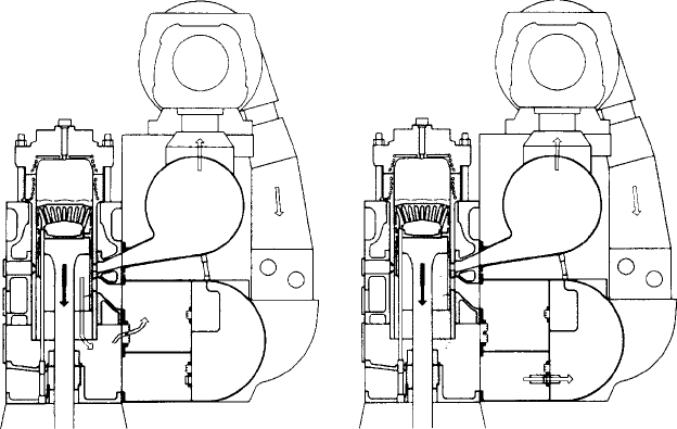
Turbocharging Arrangement
All the Sulzer RL engines employ the constant pressure turbocharging system
and with the high-efficiency Brown Boveri series 4 turbochargers include pro-
vision for automatic cleaning. The layout of the turbocharging arrangement is
shown in Figure 12.48.
The use of the piston undersides to provide a scavenge air impulse elimi-
nates the need for large electrically driven auxiliary blowers. At higher loads a
simple flap valve opens to cut out the piston underside pumping effect with a
consequent improvement in fuel consumption, whilst a small auxiliary fan incor-
porated in the scavenging system improves the smoke values at the lowest loads.
The piston underside scavenge pump facility allows the engine to start and
reverse even with total failure of all turbochargers. The auxiliary fan and engine
will even operate at up to 60 per cent load, thus giving a ‘take home’ facility.
The turbochargers are mounted on top of the large exhaust gas receiver with
the scavenge air receiver, which forms part of the engine structure beneath.
The charge air is passed down through sea water–cooled intercoolers, which
are mounted accessibly alongside the scavenge air receiver. Flap-type valves,
Sulzer rL-type engines 447
448 Wärtsilä (Sulzer) Low-Speed Engines
which operate according to the scavenge air pressure, direct the air inside the
three-compartment air receiver to the piston underside (at low scavenge air
pressure) or direct to the scavenge ports when the higher air pressure from the
turbochargers keeps the underside delivery flap valves shut.
For RL-type engines equipped with only one turbocharger, a separate tur-
bocharger/air intercooler module is available as a standard option. This unit
can be located adjacent to the engine at either the forward or aft end, thus con-
siderably reducing the mounting height and width of the main engine. The tur-
bocharger module consists of a base frame onto which the turbocharger, charge
air cooler, air ducts and cooling water pipes are solidly mounted with flexible
connections to the engine.
upgrading rLB Engines
Based on field tests carried out between 1991 and 1995, a retrofit package
of modifications was introduced for Sulzer RLB90 engines in 1993 and for
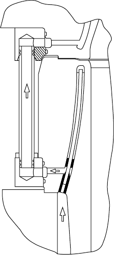
RLB66 engines in 1995. The main element is the change to loop cooling in
the cylinder liners, an improved cooling technique that reduces the thermal and
mechanical stresses in the top collar of the liner (Figure 12.49). By optimizing
the running surface temperature, the system also reduces corrosive wear and
extends the TBOs up to 2 years.
The retrofit package comprises the loop-cooled cylinder liners as well as:
l A new fully gas-tight, vermicular top piston ring of increased thickness
l A modified top piston ring groove with increased height and increased
thickness of chromium layer
FigurE 12.48 Constant pressure turbocharging and operation of under-piston
supercharging (rL engine)
l Multi-level lubrication
l A new water guide jacket to suit the new liner
l A modified condensed water drain from the scavenge air receiver.
As RLB engines exploit loop scavenging with both scavenge and exhaust
ports in the lower part of the liner, the fully gas-tight top ring significantly
reduces the lateral forces at the piston skirt in addition to reducing the blow-
by of hot combustion gases—both of which increase the piston skirt life. The
package can be applied to the engine either as a full package or step-by-step
(intermediate package) depending on service experience with the liners and
whether the general piston-running behaviour meets today’s expectations. It is
also possible to replace individual original liners with loop-cooled units when-
ever they need to be renewed; there is no problem in running loop-cooled and
original design liners together in the same engine.
(See Introduction for details of Sulzer’s early low-speed engines and
Chapter 9 for research engines).
Sulzer rL-type engines 449
FigurE 12.49 Loop cooling of the cylinder liner benets Sulzer rLB90 and rLB66
engines
451
C h a p t e r | t h i r t e e n
Burmeister & Wain
Low-Speed Engines
A pioneering Danish designer and builder of low-speed two-stroke crosshead
engines, Burmeister and Wain (B&W) focused in the post-War era on high-
pressure turbocharged single-acting uniflow-scavenged models with one cen-
trally located exhaust valve. The uniflow system fosters effective scavenging of
the exhaust gases from the cylinder in an even progressive upwards movement
with low flow resistance through to the exhaust manifold via a large diameter
poppet-type exhaust valve (Figure 13.1).
Until 1978 all B&W engines operated on the impulse turbocharging system
(Figure 13.2), but the search for enhanced economy in the wake of contempor-
ary fuel crises dictated a change to the constant pressure system, yielding a
saving of around 5 per cent in specific fuel consumption (Figure 13.3). In the
years before its takeover by MAN of Germany in 1980, B&W introduced a
number of engine series—successively the K-GF, L-GF, L-GFCA and L-GB
programmes—before launching the MC design portfolio, which is still evolv-
ing under MAN Diesel’s MAN B&W brand (see Chapter 10).
All of these designs were improved variants of the K-GF series, which
itself introduced many notable design innovations such as box-frame con-
struction, intensively cooled cylinder components and hydraulically actuated
exhaust valves.
A major change to the structure of the company followed its purchase by
MAN, resulting in Copenhagen becoming the centre for two-stroke engine
development of all designs bearing the MAN B&W trademark.
K-GF typE EnGinES
B&W two-stroke engines based on the K-GF series featured many new design
features. Notable were the box-type construction of the crankcase and the use
of a hydraulically actuated exhaust valve instead of the conventional mechani-
cal rocker arm system used in the earlier K-EF types. A sectional sketch of
the K-GF is shown in Figure 13.4. As this model was rapidly superseded by
the L-GF and L-GB models, only brief details of the K-GF construction are
given here.