Woodyard D. (ed.) Pounders Marine diesel engines and Gas Turbines
Подождите немного. Документ загружается.

462 Burmeister & Wain Low-Speed Engines
instead of to the turbochargers as in the impulse system. When the cylinders
exhaust into a large receiver, the outflow of gas is quicker because the large gas
impulse at the commencement of the exhaust period is levelled out in the gas
receiver, and the outflow of gas will not be retarded, as in the case of impulse
turbocharging where a pressure peak is built up in the narrow exhaust pipe
before the turbocharger.
The opening of the exhaust valve can be delayed about 15°, thereby length-
ening the expansion stroke and improving the efficiency and reducing the fuel
consumption. The energy before the turbine is less than that for impulse tur-
bocharging but as the pressure and temperature before the turbine is nearly
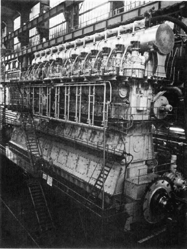
FiGurE 13.12 a 12-cylinder L90GFCa engine developing 34 800 kW at 97 rev/min
constant the turbine can be adapted to run at peak efficiency, and the blower
can supply sufficient air above 50 per cent of engine load. The scavenging air
pressure is increased and the compression pressure somewhat decreased com-
pared with impulse turbocharging.
A small auxiliary blower is necessary for satisfactory combustion condi-
tions at loads of up to about 50 per cent. Two blowers of half capacity are used
for safety, and even with one of these out of action the other with half the over-
all capacity is satisfactory for starting and load increase. The engine will still
run at down to 25 per cent load but with a smoky exhaust.
The change from K-GF to L-GF resulted in a 2 per cent improvement in
the specific fuel consumption, and the lower speed accounts for a 5 per cent
improvement in propeller efficiency. Constant pressure turbocharging adds a
further 5 per cent to the improvement, resulting in a 12 per cent reduction in
specific fuel consumption between the L-GF and K-GF types. The next engine
model of the constant pressure turbocharged type was the L-GFCA ((Figures
13.12 and 13.13), shortly succeeded by the L-GB type., shortly succeeded by the L-GB type.
L-GB typE EnGinES
A further improvement in specific fuel consumption was yielded by the L-GB
and L-GBE series engines. By using the optimum combination of longer stroke,
increased output and higher maximum pressure and the newest high-efficiency
L-GB type engines 463
100%
90
80
70
80 85 90 95 100
(n(r/min))
90
80
10
11
12
13
14
P
b
0.20
0.25
0.30
P
b
(bar)
85 90 95 100% 105
110
7
2
110
100%
5
1
4
6
3
4500
4400
4300
4200
4100
4000
3900
3800
3700
3600
3500
3400
3300
3200
3100
3000
2900
2800
2700
2600
BHP/cyl.
3300
kW/cyl.
3200
3100
3000
2900
2800
2700
2600
2500
2400
2300
2200
2100
2000
1900
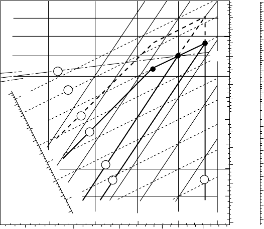
FiGurE 13.13 Load diagram for L90GFCa engine
464 Burmeister & Wain Low-Speed Engines
turbochargers, much lower fuel consumption rates were achieved. The L-GB
series had an mep of 15 bar at the same speed as that of the L-GFCA to give
an increase in power of 15 per cent and an increase in the firing pressure from
89 bar to 105 bar. Accordingly, the important P
max
/mep ratio is almost the same,
but the specific fuel consumption is some 4 g/kW h lower than that of the
L-GFCA series. A further economy rating is obtained with engines of the L-GBE
type by holding the P
max
at reduced engine output (the so-called derating, as
outlined in Chapter 5: the practice of offering propulsion engines in both normal
and derated versions was adopted by many engine manufacturers, even for four-
stroke medium-speed engines) (Figure 13.14).
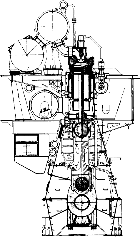
FiGurE 13.14 L-GB/GBE engine cross section
Bedplate and Main Bearing
The bedplate consists of high, welded longitudinal girders and welded cross
girders with cast steel bearing supports. For the four- and five-cylinder engines,
the chain drive is placed between the aftermost cylinder and the built-in thrust
bearing. For the six- to twelve-cylinder engines, the chain drive is placed at
the assembling between the fore and the aft part. For production reasons, the
bedplate can be made in convenient sections. The aft part contains the thrust
bearing. The bedplate is made for long, elastic holding-down bolts tightened
by hydraulic tool.
The oil pan is made of steel plate and welded to the bedplate parts. The oil
pan collects the return oil from the forced lubricating and cooling oil system.
For about every third cylinder, it is provided with a drain with grid.
The main bearings consist of steel shells lined with white metal. The bot-
tom shell can, by means of hydraulic tools for lifting the crankshaft and a
hook-spanner, be turned out and in. The shells are fixed with a keep and the
long elastic studs tightened by hydraulic tool.
thrust Bearing
The thrust bearing is of the B&W–Michell type. Primarily, it consists of a steel
forged thrust shaft, a bearing support and segments of cast iron with white
metal. The thrust shaft is connected to the crankshaft and the intermediate shaft
with fitted bolts.
The thrust shaft has a collar for transfer of the ‘thrust’ through the seg-
ments to the bedplate. The thrust bearing is closed against the crankcase and
provided with a relief valve.
Lubrication of the thrust bearing derives from the system oil of the engine.
At the bottom of the bearing, there is an oil sump with outlet to the oil pan.
Frame Section
The frame section for the four- and five-cylinder engines consists of one part
with the chain drive-located aft. The chain drive is closed by the end-frame
aft. For six- to twelve-cylinder engines the frame section consists of a fore and
an aft part assembled at the chain drive. Each part consists of an upper and a
lower frame box, mutually assembled with bolts.
The frame boxes are welded. The upper frame box is on the back of the
engine provided with an inspection cover for each cylinder. The lower frame box
is on the front of the engine provided with a large hinged door for each cylinder.
The guides are bolted onto the upper frame box and offer possibility for
adjustment. The upper frame box is provided on the backside with a relief valve
for each cylinder and on the front side with a hinged door per cylinder. A slotted
pipe for cooling oil outlet from the piston is suspended in the upper frame box.
The frame section is attached to the bedplate with bolts. The stay bolts con-
sist of two parts assembled with a nut. To prevent transversal oscillations the
assembly nut is supported. The stay bolts are tightened hydraulically.
L-GB type engines 465
466 Burmeister & Wain Low-Speed Engines
Cylinder Frame, Cylinder Liner and Stung Box
The cylinder frame unit is made of cast iron. Together with the cylinder liner
(Figure 13.15), it forms the scavenging air space and the cooling water space.
At the chain drive there is an intermediate piece. The stay bolt pipes and the
double bottom in the scavenging air space are water cooled. On the front the
cylinder frame units are provided with a cleaning cover and inspection cover for
scavenging ports. The cylinder frame units are mutually assembled with bolts.
Housings for roller guides, lubricators and gallery brackets are suspended
on the cylinder frame unit. Further, the outside part of a telescopic pipe is fixed
for the supply of piston cooling oil and lubricating oil. A piston rod stuffing
box provided with sealing rings for scavenging air and oil scraper rings pre-
venting oil from coming up into the scavenging air space is at the bottom of
the cylinder frame unit.
A–A
B–B
A
B
B
A
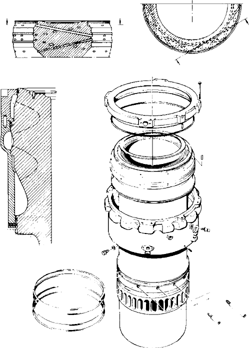
FiGurE 13.15 Components of L-GB cylinder liner
The cylinder liner is made of alloyed cast iron and is suspended in the
frame section with a low located flange. The uppermost part of the liner has
drillings for cooling water and is surrounded by a cast iron cooling jacket. The
cylinder liner has scavenging ports and drillings for cylinder lubrication.
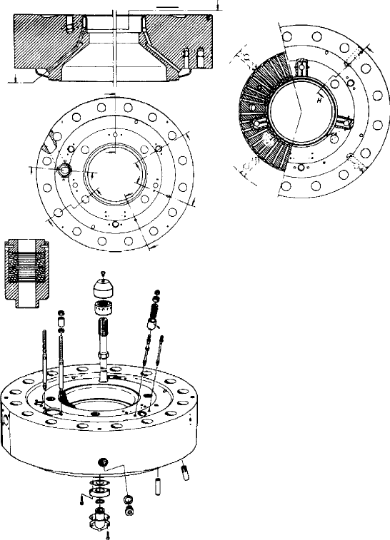
Cylinder Cover
The cylinder cover is made in one piece of forged steel and has drillings for
cooling water. It has a central bore for the exhaust valve and bores for fuel
valves, safety valve, starting valve and indicator valve (Figure 13.16).
The cylinder cover is attached to the cylinder frame with studs tightened by
a hydraulic ring covering all studs.
L-GB type engines 467
G–G
H–H
A
A
A–A
B
G
F
E
D
G
B
F
E
D
C
C
H
FiGurE 13.16 Components of L-GB cylinder cover
468 Burmeister & Wain Low-Speed Engines
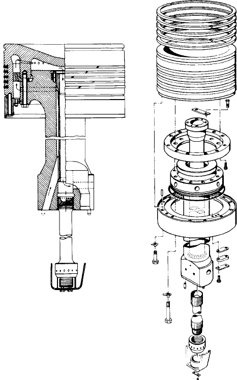
Exhaust Valve and Valve Gear
The exhaust valve consists of a valve housing and a valve spindle. The valve
housing is made of cast iron and arranged for water cooling, and is provided
with a bottom piece of steel with Stellite welded onto the seat. The spindle
is made of heat-resistant steel with Stellite welded onto the seat. The hous-
ing is provided with a spindle guide. The exhaust valve housing is connected
to the cylinder cover with studs and nuts tightened by hydraulic jacks. The
exhaust valve is opened hydraulically and closed by a set of helical springs.
The hydraulic system consists of a piston pump mounted on the roller guide
housing, a high-pressure pipe and a working cylinder on the exhaust valve. The
piston pump is activated by a cam on the camshaft.
Cover Mounted Valves
In the cylinder cover, there are three fuel valves: a starting valve, a safety valve,
and an indicator valve.
The fuel valve opening is controlled by the fuel oil pressure and is closed
by a spring. An automatic vent slide allows circulation of fuel oil through the
valve and high-pressure pipes and prevents the compression chamber from
being filled up with fuel oil in the event of a sticking spindle in a stopped
engine. Oil from venting and other drains is led away in a closed system.
The starting valve is opened by control air from the starting air distributor
and closed by a spring. The safety valve is spring loaded. The indicator valve
is placed near the indicator gear.
Crankshaft
The crankshaft for four- and five-cylinder engines is made in one part, and for
six- to twelve-cylinder engines in two parts assembled at the chain drive with
fitted bolts. The crankshaft is semi-built with forged steel throws.
In the aft end the crankshaft features a flange for assembling with the thrust
shaft. The crankshafts are balanced exclusively by borings in the crankpins,
although in some cases supplemented by balance weight in the turning wheel.
Connecting rod
The connecting rod is made of forged steel. It has a Tee-shaped base on which
the crank bearing is attached with hydraulically tightened bolts and nuts with
Penn-securing. The L90GBE engine has shims placed between the base and
the crank bearing, as this engine type needs a smaller compression chamber
because of a higher compression ratio. The top is square shaped on which the
crosshead bearings are attached with hydraulically tightened studs and nuts
with Penn-securing. The bearing parts are mutually assembled with bolts and
nuts tightened by hydraulic jacks.
The lubrication of the crank bearing takes place through a central drilling
in the connecting rod.
The crank bearing is made of steel cast in two parts and lined with white
metal. The bearing clearance is adjusted with shims. The crosshead bearings
are made of cast steel in two parts and provided with bearing shells.
piston–piston rod–Crosshead
The piston consists of a piston crown, piston skirt and cooling insert for oil
cooling (Figure 13.17). The crown is made of heat-resisting steel and is pro-
vided with five ring grooves, which are hard-chrome plated on both lands. The
skirt is made of cast iron. The piston rings are right- and left-angle cut and of
the same height.
The piston rod is made of forged steel and fixed to the crosshead with a
hydraulic tightened stud. It features a central bore, which, in connection with
a cooling oil pipe and the cooling insert, forms the inlet and outlet for cooling oil.
L-GB type engines 469
FiGurE 13.17 Components of L-GB piston
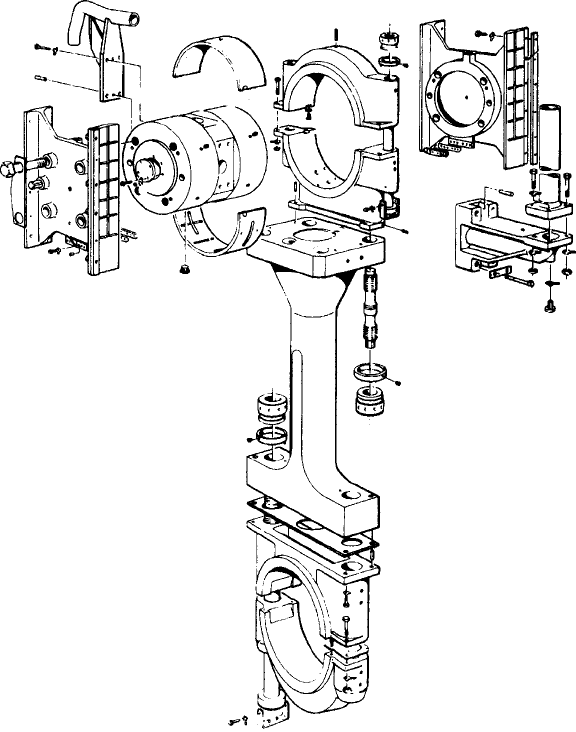
470 Burmeister & Wain Low-Speed Engines
The crosshead is made of forged steel and is provided with steel cast guide
shoes with white metal on the running surfaces. A bracket for oil inlet from
the telescopic pipe and a bracket for oil outlet to slit pipe are mounted on the
crosshead ((Figure 13.18)..
Fuel pump and Fuel Oil High-pressure pipes
The fuel pump consists of a pump housing of nodular cast iron and a centrally
placed pump cylinder of steel with sleeve and plunger of nitrated steel. The
plunger has an oblique injection edge, which will automatically give an opti-
mum fuel injection timing. There is one pump for each cylinder. In order to
prevent fuel oil from being mixed into the separate lubricating system on the
camshaft, the pump is provided with a sealing device.
FiGurE 13.18 Components of L-GB connecting rod and crosshead
The pump gear is activated by the fuel cam, and the injected volume is
controlled by turning the plunger by a toothed bar connected to the regulation
mechanism. Adjustment of the pump lead is made with shims between top
cover and pump housing.
The fuel pump is provided with a pneumatic lifting device, which can, dur-
ing normal operation and turning, lift the roller guide roller free of the cam.
The fuel oil high-pressure pipes have protecting hoses. The fuel oil system
is provided with a device, which, through the pneumatic lifting tool, discon-
nects the pump in case of leakage from the high-pressure pipes.
Camshaft and Cams
The camshaft is divided into sections for each cylinder. The individual sections
consist of a shaft piece with an exhaust cam, a fuel cam, an indicator cam, and
coupling parts. The exhaust and fuel cams are made of steel with a hardened
roller race and are shrunk on the shaft. They can be adjusted and dismounted
hydraulically.
The indicator cams, which are made of cast iron, are bolted onto the shaft.
The coupling parts are shrunk on the shaft and can be adjusted and dismounted
hydraulically.
The camshaft is located in the housing for the roller guide. The camshaft
bearings consist of two mutually interchangeable bearing shells, which are
mounted in hydraulically tightened casings.
Chain drive and reversing
The camshaft is driven from the crankshaft by two 4
1
⁄2-in chains. The chain
drive is provided with a chain tightener, and guide bars support the long chain
strands. The camshaft is provided with a hydraulically actuated reversing gear
turning the camshaft to the position corresponding to the direction of rotation
of the crankshaft.
Starting air distributor, governor and cylinder lubricators are driven by sep-
arate chain from the intermediate wheel.
Moment Compensator
Four-, five- and six-cylinder engines are prepared for moment compensators,
which can be fixed to the fore and aft ends of the frame section and are driven
by the camshaft through flexible couplings. The moment compensator will
reduce the second-order external moments to a level between a quarter of the
original figure and zero.
Governor
The engine revolution per minute is controlled by a hydraulic governor. For
amplification of the governor’s signal to the fuel pump, there is a hydraulic
amplifier. The hydraulic pressure for the amplifier is delivered by the camshaft
lubricating oil system.
L-GB type engines 471