Woodyard D. (ed.) Pounders Marine diesel engines and Gas Turbines
Подождите немного. Документ загружается.

472 Burmeister & Wain Low-Speed Engines
Cylinder Lubricators
The cylinder lubricators are mounted on the cylinder frame, one per cylinder,
and interconnected with shaft pieces. The lubricators have built-in adjustment of
the oil quantity. They are of the ‘sight feed lubricator’ type, and each lubricating
point has a glass. The oil is led to the lubricator through a pipe system from an
elevated tank. A heating element rated at 75 W is built into the lubricator.
Manoeuvring System (Without Bridge Control)
The engine is provided with a pneumatic manoeuvring and fuel oil regulating
system, which transmits orders from the separate manoeuvring console to the
engine.
By means of the regulating system, it is possible to start, stop, reverse
and control the engine. The speed control handle in the manoeuvring console
activates a control valve, which gives a pneumatic speed-setting signal to the
governor depending on the desired number of revolutions. The start and stop
functions are controlled pneumatically. At a shutdown function, the fuel pumps
are moved to zero position independent of the speed control handle.
Reversing of the engine is controlled pneumatically through the engine tel-
egraph and is effected via the telegraph handle.
Reversing takes place by moving the telegraph handle from ‘ahead’ to
‘astern’ and by moving the speed control handle from ‘stop’ to ‘start’ position.
Control air then moves the starting air distributor and, through the pressurizer,
the reversing mechanism to the ‘astern’ position.
turning Gear and turning Wheel
The turning wheel has cylindrical teeth and is fitted to the thrust shaft; it is
driven by a pinion on the terminal shaft of the turning gear, which is mounted
on the bedplate. The turning gear is driven by an electric motor with built-
in gear and brake. Further, the gear is provided with a blocking device that
prevents the main engine from starting when the turning gear is engaged.
Engagement and disengagement of the turning gear is executed by axial trans-
fer of the pinion.
Gallery Brackets
The engine is provided with gallery brackets placed at such a height that the
best possible overhaul and inspection conditions are obtained. The main pipes
of the engine are suspended in the gallery brackets.
A crane beam is placed on the brackets below the centre gallery manoeu-
vring side.
Scavenging air System
The air intake to the turbocharger takes place directly from the engineroom
through the intake silencer of the turbocharger. From the turbocharger the air is
led via charging air pipe, air cooler and scavenging air pipe to the scavenging
ports of the cylinder liner. The charging air pipe between turbocharger and air
cooler is provided with a compensator and insulated.
Exhaust turbocharger
The engine is as standard arranged with MAN or BBC (now ABB) turbocharg-
ers. The turbochargers are provided with a connection for Disatac electronic
tachometers, and prepared for signal equipment to indicate excessive vibration
of the turbochargers. For water cleaning of the turbine blades and the nozzle
ring during operation, the engine is provided with connecting branches on the
exhaust receiver in front of the protection grid.
Exhaust Gas System
From the exhaust valves the gas is led to the exhaust gas receiver where the
fluctuating pressure will be equalized and the gas led further on to the tur-
bochargers with a constant pressure. After the turbochargers, the gas is led
through an outlet pipe and out in the exhaust pipe system.
The exhaust gas receiver is made in one piece for every cylinder and con-
nected to compensators. There are also inserted compensators between the
receiver and the exhaust valves and between the receiver and the turbocharger.
For quick assembling and dismantling of the joints between the exhaust
gas receiver and the exhaust valves, a clamping band is fitted. The exhaust gas
receiver and exhaust pipe are provided with insulation covered by a galvanized
steel plate.
There is a protection grid between the exhaust gas receiver and each
turbocharger.
auxiliary Blower
The engine is provided with two electrically driven blowers, which are
mounted in each end of the scavenging air receiver as standard. The suction
sides of the blowers are connected to the pipes from the air coolers, and the
non-return valves on the top of the outlet pipes from the air coolers are closed
as long as the auxiliary blowers can give a supplement to the scavenging air
pressure.
The auxiliary blowers will start operating before the engine is started and
will ensure complete scavenging of the cylinders in the starting phase, which
gives the best conditions for a safe start.
During operation of the engine, the auxiliary blowers will start automati-
cally every time the engine load is reduced to about 30–40 per cent, and they
will continue operating until the load is again increased to over approximately
40–50 per cent.
In cases when one of the auxiliary blowers is out of service, the other aux-
iliary blower will automatically function correctly in the system without any
manual readjustment of the valves being necessary. This is secured by auto-
matic non-return valves in the suction pipe of the blowers.
L-GB type engines 473
474 Burmeister & Wain Low-Speed Engines
Starting air System
The starting air system contains a main starting valve (two ball valves with
actuators), a non-return valve, a starting air distributor and starting valves. The
main starting valve is combined with the manoeuvring system, which controls
start and ‘slow turning’ of the engine. The slow turning function is actuated
manually from the manoeuvring stand.
The starting air distributor regulates the control air to the starting valves so
that these supply the engine with air in the firing order. The distributor has one
set of starting cams for ‘ahead’ and ‘astern’, respectively, and one control valve
for each cylinder.
475
C h a p t e r | f o u r t e e n
Doxford Low-Speed
Engines
The last British-designed low-speed two-stroke engine—the distinctive
Doxford opposed-piston design—was withdrawn from production in 1980, but
a few of the J-type (Figure 14.1) remain in service and merit description. In its
final years the company also designed and produced the unusual three-cylinder
58JS3C model, which developed 4050 kW at 220 rev/min and was specified
to power several small container ships. The 58JS3C design (Figure 14.2) was
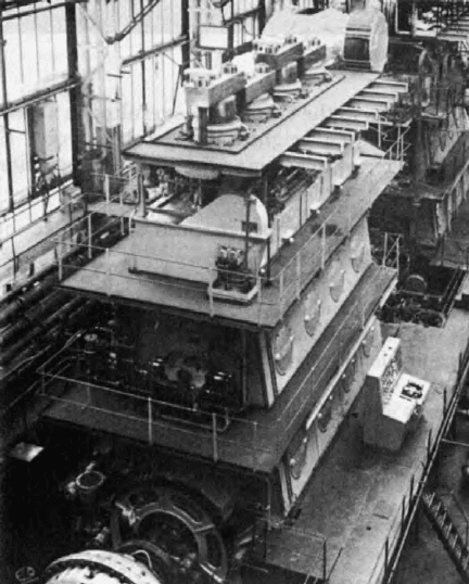
FigurE 14.1 A Doxford 76J4 engine on the testbed
476 Doxford Low-Speed Engines
based on the J-type but with refinements addressing the higher rotational speed
and relatively short piston stroke.
DoxForD J-typE
Doxford J-type engines were built in long- and short-stroke versions in bore
sizes of 580 mm, 670 mm and 760 mm, and with three to nine cylinders deliv-
ering up to around 20 000 kW (Table 14.1). The engine is a single-acting two-
stroke opposed-piston type with each cylinder having two pistons, which move
in opposite directions from a central combustion chamber.
The pistons in each cylinder are connected to a three-throw section of the
crankshaft, the lower piston being coupled to the centre throw by a single con-
necting rod, crosshead and piston rod. Each pair of the side cranks is connected
to the upper piston by two connecting rods, crossheads and side rods. As the
pistons move towards each other, air is compressed in the cylinder, and, shortly
before reaching the point of minimum volume between the pistons (inner dead
centre), fuel at high pressure is injected through the injector nozzles into the
combustion space (Figure 14.3).
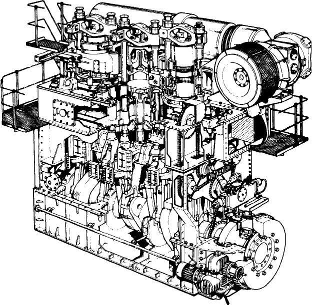
FigurE 14.2 Cutaway drawing of a 58JS3C engine
Doxford J-type 477
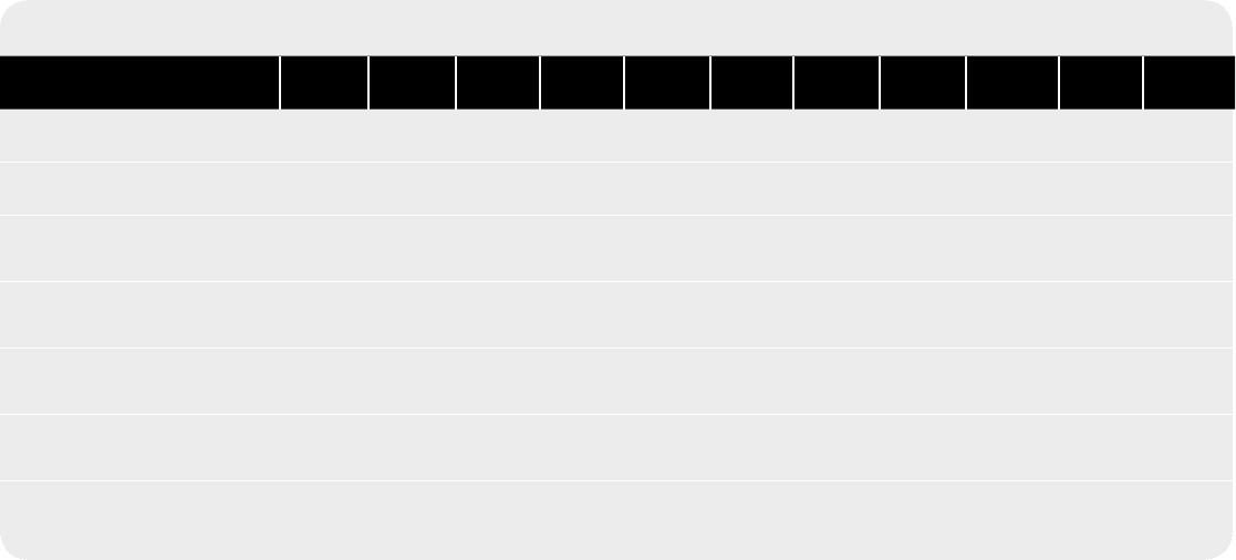
table 14.1 Doxford low-speed engines
Engine type 58J4 67J4 67J5 67J6 76J3 76J4 76J5 76J6 76J7 76J8 76J9
Number of cylinders 4 4 5 6 3 4 5 6 7 8 9
Cylinder bore (mm) 580 670 670 670 760 760 760 760 760 760 760
Stroke upper piston (mm) 480 500 500 500 520 520 520 520 520 520 520
Stroke lower piston (mm)
1 370 1 640 1 640 1 640 1 660 1 660 1 660 1 660 1 660 1 660 1 660
Combined piston stroke (mm) 1 850 2 140 2 140 2 140 2 180 2 180 2 180 2 180 2 180 2 180 2 180
Number of turbochargers 1 1 2 2 1 1 2 2 3 3 4
Weight (excluding oil and water,
tonnes)
175 270 320 370 270 335 400 470 540 600 680
(Continued)

478 Doxford Low-Speed Engines
table 14.1 (Continued)
Engine type 58J4 67J4 67J5 67J6 76J3 76J4 76J5 76J6 76J7 76J8 76J9
Ratings
Maximum continuous rating
(mcr) (bhp metric)
7 500 9 000 11 000 13 500 9 000 12 000 15 000 18 000 21 000 24 000 27 000
Engine speed (rev/min) 160 127 127 127 123 123 123 123 123 123 123
Brake mean eective pressure
(bmep) (bar)
10.57 10.34 10.34 10.34 10.81 10.81 10.81 10.81 10.81 10.81 10.81
recommended max service
power (90% mcr)
6 750 8 100 9 900 12 200 8 100 10 800 13 500 16 200 18 900 21 600 24 300
Engine speed (rev/min) 155 123 123 123 119 119 119 119 119 119 119
Brake mean eective pressure
(bmep) (bar)
9.82 9.61 9.61 9.61 10.06 10.06 10.06 10.06 10.06 10.06 10.06
Consumption
Fuel consumption
150–153 g/bhp h with HV fuel of 10 000 kcal/kg
Cylinder lubricating oil 0.45 g/bhp h
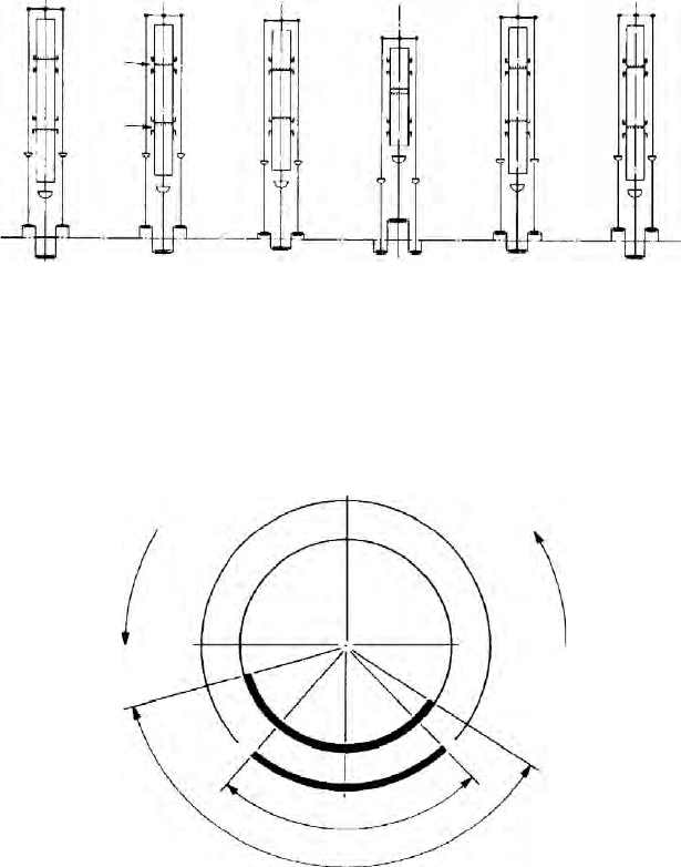
During the first stages of combustion, the pressure in the cylinder contin-
ues to rise until a maximum value is reached soon after the pistons begin to
move apart. After combustion is completed, the hot gases continue to expand,
thereby forcing the pistons apart until the exhaust ports in the upper liner are
uncovered by the upper piston. As the exhaust ports open, the hot gases in the
cylinder, now at a reduced pressure, are discharged to the turbine of the turbo-
chargers, so causing the pressure in the cylinder to drop to a level just below
that of the scavenge air. At this point the air inlet ports in the lower liner are
uncovered by the lower piston, so allowing air under pressure, which is deliv-
ered to the scavenge space by the turbocharger, to flow through the cylinder
and expel the remaining burnt gases (Figure 14.4a).
During the inward compression stroke of the pistons, the air inlet ports are
closed just before the exhaust ports. The air in the cylinder is then compressed
and the cycle repeated. The opening and closing of the exhaust and air inlet
ports are shown diagrammatically in the typical timing diagram (Figure 14.4b).
This diagram is constructed with reference to the inner dead centre position;
the unsymmetrical timing of the ports is due to the fact that the side cranks are
at an angle of more than 180° from the centre crank. The angle of lead of the
side cranks varies with the size of the engine.
The upper piston of the engine requires its own running gear and crank
throws. The advantages obtained with this concept are considerable. For equal
Doxford J-type 479
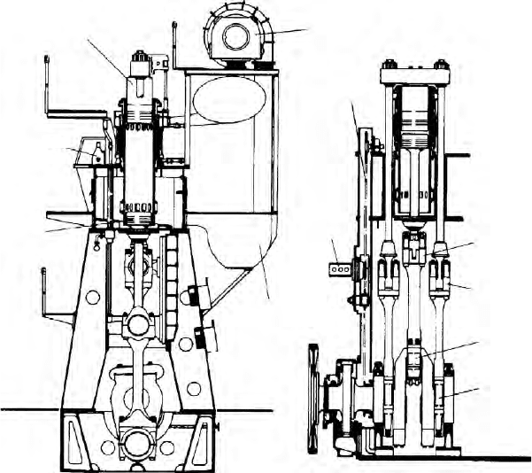
Water-cooled
upper piston
Scavenge
air
Camshaft and
fuel pump
chaindrive
Fuel pump
Side bottom
end bearing
Centre bottom
end bearing
Oil-cooled
lower piston
Exhaust gas
turbocharger
Centre top
end bearing
Side top
end bearing
Fuel injection
timing valve
FigurE 14.3 Doxford J-type conguration
480 Doxford Low-Speed Engines
mean indicated pressure, mean piston speed and cylinder bore, the Doxford
opposed-piston engine will develop 30–40 per cent higher power per cylinder
than a single-piston engine. The first-order inertia force from the lower piston
is balanced against the corresponding force from the upper pistons, and a well-
balanced engine is obtained. All of the forces from the upper piston are trans-
ferred through the running gear.
Long tension bolts, as used in single-piston engines to transfer the forces
from the cylinder covers to the bedplate, are not required in the opposed-
piston engine. The engine structure is therefore simple and relatively free from
stresses. No valves are required in the scavenge-exhaust system, and the scav-
enge efficiency of the cylinders is high. The flow areas through the exhaust ports
Inner dead centre
0
90
Exhaust ports open
Air
opens
90
opens
closes
Exhaust
Exhaust
Centre crank
angle
before
inner dead
centre
Centre
crank angle
after
inner dead
centre
Air
closes
180
Air inlet ports open
(b)
FigurE 14.4b port timing diagram for Doxford 76J4C engine
Exhaust
ports
Scavenge
ports
1
Scavenge and
exhaust ports fully
open
6
Scavenge ports
open scavenging
commences
2
Scavenge ports
closed exhaust
ports still open
3
Exhaust ports
closed
compression
commences
4
Inner dead
centre
combustion
taking place
5
Exhaust ports
open exhaust
gases escape
(a)
FigurE 14.4a Exhaust and scavenge events
are substantial, and fouling, which inevitably takes place in service, has little
effect. The large port areas also make the engine well suited for turbocharging.
Engine Construction
The bedplate is built up of two longitudinal box girders extending over the full
length of the engine. The transverse girders, which incorporate the main bear-
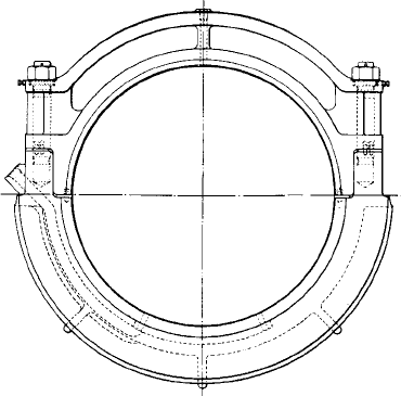
ing housings, are welded to these longitudinal members. A semi-circular white
metal–lined steel shell forms the lower half of each main bearing and is held in
place by a keep secured by studs to the bedplate ((Figure 14.5)..
The entablature is also a welded steel box construction, arranged to carry
the cylinders, which are bolted to the upper face. It is bolted to the tops of the
columns and to the crosshead guides. The entablature forms the air receiver
from which the cylinders are supplied with air, and its volume is supplemented
by the air receiver on the back of the engine, whose top face forms the back
platform. The intercoolers are mounted on this receiver and the air deliveries
from the turbochargers are connected to these coolers. Alternatively, in the
case of engines with end-mounted turbochargers, the air from the turbocharger
is supplied directly to the entablature after passing through the end-mounted
intercoolers.
Crankshaft
Each cylinder section of the crankshaft is made up of three throws, the two side
cranks being connected to the upper piston and the centre crank to the lower
piston. The side crankwebs are circular and form the main bearing journals.
Each centre crank is made of an integral steel casting or forging for semi-built
shafts. For fully built shafts these units are made of two slabs shrunk onto the
centre pin. The centre cranks are shrunk onto the side pins.
Doxford J-type 481
FigurE 14.5 Main bearing assembly