Woodyard D. (ed.) Pounders Marine diesel engines and Gas Turbines
Подождите немного. Документ загружается.

for better distribution. A new exhaust valve cage (Figure 28.5) with a thin-
ner seat wall and more efficient cooling from improved water circulation was
specified to reduce the valve seat temperature and extend valve life when the
engine burns fuels with high sodium and vanadium contents. Better cooling of
the cage seat and effective pulse turbocharging lowered the temperature of the
grandi Motori trieste 721
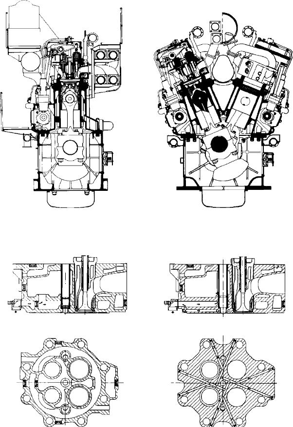
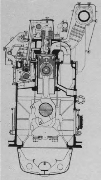
FigurE 28.3 gMt’s Bl550 design in in-line and V-cylinder form
Original version Bore-cooled version
A B
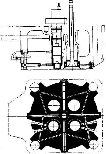
FigurE 28.4 Sections through gMt B550 cylinder head (left) and the redesigned
Bl550 component
722 Other Medium-Speed Engines
continuously rotated composite exhaust valves which comprise a Nimonic 80A
alloy head and anti-corrosion coated steel stem.
A much stiffer cylinder liner unit (Figure 28.6) was designed, without a
heat shield and bore cooled at the top near the gas-side wall. The cooling bores
are of the blind type in which the inlet and outlet water flows are separated
by diaphragms, allowing the radial outlet holes to be positioned in the lower
part of the liner and thus eliminate a concentration of stresses in those areas
most affected by dynamic load fluctuations below the cylinder head gasket.
Tests showed that the bore-cooling arrangement secures a lower peak tempera-
ture and a more uniform distribution on the piston ring rubbing surface. Load-
dependent cooling was specified as standard.
The composite pistons (steel crown and aluminium alloy skirt) carry three
compression and one oil scraper ring in chromed grooves. The upper two com-
pression rings were increased in thickness to withstand the higher combustion
pressure and reduce torsional deformation.
A subsequent development programme in 1992/93 resulted in the A55
design (Figure 28.7) which retained the 550 mm bore of its precursors but
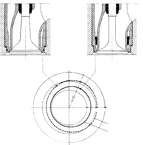
1—Original valve cage
Exhaust gas
Flywheel side
200° 300°
400°
2—Valve cage with improved cooling
1
2
FigurE 28.5 temperature distributions of the gMt B550 valve cage and the
improved design for the Bl550 engine (21 bar mep and 450 rev/min)
featured an extended stroke (680 mm). An eight per cent power increase over
the BL550 series was derived—taking the specific output to 1250 kW/cylinder
at 425 rev/min—along with enhanced fuel economy. The redesign also sought sim-
plified maintenance procedures and higher reliability from a range comprising six,
eight and nine in-line and V12-, 14-, 16- and 18-cylinder models covering a power
band up to 22 500 kW. Special propulsion market targets included cruise ships and
high-powered ferries, GMT citing the low height of the A55 engine for its power
output: 5.765 m for the in-line version and 5.67 m for the V-cylinder model.
grandi Motori trieste 723
A
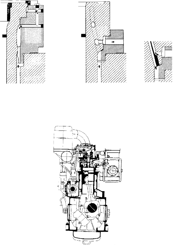
Composite version Bore-cooled version Cooling hole detail
with internal
diaphragm
B
FigurE 28.6 improved cooling arrangement for gMt Bl550 cylinder liner (B) over
original conguration (A)
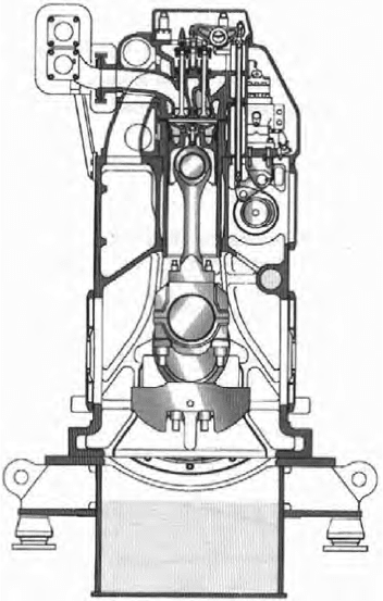
FigurE 28.7 gMt’s A55 design
724 Other Medium-Speed Engines
The A55 benefited from GMT’s technical collaboration with New Sulzer
Diesel, permitting elements of the Swiss designer’s successful ZA40S medium-
speed engine to be exploited. The longer stroke took the stroke/bore ratio from
1.15 to 1.24:1, giving a better thermal efficiency. This was achieved without
raising the cylinder head; a more compact piston allowed the same head cast-
ing to be used. A reduction in engine speed compared with the BL550 limited
the mean piston speed and yielded the increased output with virtually the same
brake mean effective pressure as the earlier model.
Fuel injection system improvements were also made. Fuel enters the valve
laterally rather than vertically, underwriting a reduced fuel pipe length and a
shorter fuel valve. The injection itself takes place over a shorter period, cover-
ing around 30° of the cycle, and at a higher pressure (around 1200 bar).
The crank mechanism and other components were also redesigned, mainly
to simplify maintenance. The connecting rod, for example, is in three parts (a
shank and two caps) connected by hydraulically tightened studs. Despite the
longer stroke, it was possible to house the crank mechanism in the same crank-
case as the BL550 by redesigning the crankshafts and connecting rods. The
bedplate and cylinder block remained virtually unchanged.
Most notable of the A55 refinements was the adoption of Sulzer’s unique
rotating piston concept, previously unique to the ZA40S engine and its pred-
ecessors (Chapter 26). A bore-cooled steel crown is mated with a cast iron
skirt. Cast iron rather than aluminium alloy was specified to allow the operat-
ing clearance of the skirt to be reduced; this, together with the inertia from
the rotating piston, reduces impact velocities with the liner resulting from pis-
ton slap. The rotating piston (Figure 28.8) underwrites reliability and a lower
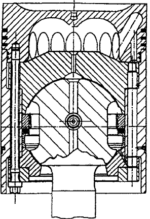
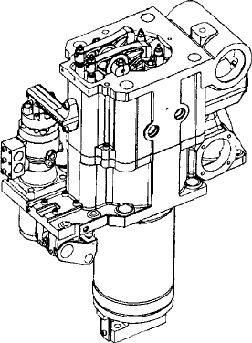
FigurE 28.8 gMt’s A55 design beneted from a Sulzer-derived rotating piston
lubricating oil consumption. Simpler and more efficient turbocharging was
introduced. In-line and V-cylinder propulsion engines are served by a single-
pipe exhaust system associated with high efficiency and compact configura-
tion; an air/gas bypass is also provided.
GMT was also active in the popular 320 mm bore class, its A32 design
having emerged in the 1990s as a longer stroke derivative of the A320 engine
introduced in 1986. The 320 mm bore/390 mm stroke A32 series (Figure 28.9)
had a maximum continuous rating of 440 kW/cylinder at 750 rev/min and was
produced in six, eight and nine in-line and V12-, 14- and 16-cylinder versions
to cover a power range up to 7040 kW.
A monobloc casting of high-strength iron arranged for an underslung
crankshaft forms the structure of both in-line and V-cylinder engines. The
high-strength lamellar iron cylinder head (Figure 28.10) is secured by four stud
bolts for ease of dismantling and has a thick bore-cooled bottom plate for low
thermal loading and high stiffness. The inserted thin-walled exhaust valve seat
rings are directly cooled by water circulation to achieve a low seat temperature
and extended time-between-overhauls on heavy fuel.
High-strength cast iron cylinder liners have a thick bore-cooled collar for
low mechanical and thermal stresses. The composite pistons feature thin-forged
grandi Motori trieste 725
FigurE 28.9 gMt A32 design
726 Other Medium-Speed Engines
steel crowns and aluminium alloy skirts. The connecting rods are drop forged
in two pieces and withdrawable from the top along with the piston.
Reliable operation on residual fuels was addressed by basic design para-
meters (mean piston speed, compression ratio, combustion pressure and air–
fuel ratio) and attention to key component and system design, GMT citing:
l A facility to provide automatic load-dependent control of jacket cooling
water and charge air temperatures, gradually raising them with dimin-
ishing load to improve combustion, reduce fouling and maintain the
combustion chamber walls above the acidic condensation temperature to
prevent cold corrosion.
l Exhaust valves of Nimonic 80A material with corrosion-resistant coated
stems and rotating devices to prevent hot spots.
l Forged steel piston crown carrying corrosion- and wear-resistant
plasma-coated rings.
l High-pressure fuel injection system ensuring fine atomization for better
ignition; and availability of a remote-controlled facility for recirculation
of fuel through the injectors at engine standstill for starting on fuels of
the highest viscosities.
l Bore cooling of the hot components of the combustion chamber (cyl-
inder liner, head and exhaust valve seats) through machined passages,
allowing precise temperature control in inhibiting both hot and cold
corrosion.
FigurE 28.10 Section and plan of gMt A32 cylinder head
GMT also developed 420 mm bore engines for a number of years. The
A420 had a stroke of 500 mm and ran at 500 rev/min to deliver 515 kW/cylin-
der, while the shorter-stroke (480 mm) A420H ran at 600 rev/min for an output
of 588 kW/cylinder.
Higher speed 230 mm bore GMT engines are covered in Chapter 30.
hiMSEn (hyunDAi hEAVy inDuStriES)
A prolific South Korean builder of two-stroke and four-stroke diesel engines
under licence, Hyundai Heavy Industries developed its first own-design
medium-speed engine, the 210 mm bore HiMSEN H21/32 series, for launch-
ing in 2001. Since then the HiMSEN brand has expanded to embrace 170 mm,
250 mm and 320 mm bore models based on common design principles and cov-
ering power demands up to 10 000 kW for genset and propulsion plant applica-
tions. Home and export market penetration was swiftly achieved, supported by
installations for the HHI group’s substantial newbuilding commitments.
Initially targeting marine genset drives, the H21/32 engine was also
intended for propulsion markets (Figure 28.11). A heavy fuel-burning 210 mm
bore/320 mm stroke design was selected for development; the high stroke/
bore ratio (1.52) and high compression ratio (17) were considered appropriate
hiMSEn (hyundai heavy industries) 727
FigurE 28.11 Cross-section of hiMSEn h21/32 engine, whose design principles
were extended to 170 mm, 250 mm and 320 mm models
728 Other Medium-Speed Engines
for fuel economy and low NOx emissions. A simplified configuration with a
minimal number of components was pursued to enhance reliability and to ease
production and maintenance. Two sets of prototypes were built and tested to
confirm engine performance and reliability. The current programme covers a
power band from 1200 kW to 1800 kW at 900 rev/min with in-line six-, eight-
and nine-cylinder models; specific ratings from 150 kW to 200 kW per cylinder
at 720/750/900 and 1000 rev/min are delivered.
Key structural and running elements of the design were optimized for
Hyundai’s production facilities, with generous dimensions underwriting mod-
erate fatigue safety factors. Ease of maintenance was addressed by adopting
a cylinder unit concept, allowing the cylinder head, valve train, fuel injection
equipment, cylinder liner, piston and connecting rod to be withdrawn as an
assembly for servicing onboard or ashore (Figure 28.12).
The engine block is a simple and robust structure of nodular cast iron. A
large volume of combustion air chamber and lubricating oil channel is incorpo-
rated but water spaces are excluded to avoid any risk of corrosion and flooding
into the oil chamber. The nodular cast iron cylinder head features a V-type fire
deck support to combat the high maximum firing pressure (200 bar); the inlet
and exhaust ports were evolved in-house by Hyundai using its own flow test
rig and computational fluid dynamics (CFD) analysis. The structural design of
the head and the cylinder liner was optimized based on the CFD analysis of
coolant flow as well as finite element analysis.
The two-piece piston comprises a steel crown and box-type steel skirt,
delivering lower deformation under high cylinder pressure. Two compression
rings and one oil scraper ring are fitted, the top ring coated with chromium-
ceramic material on its running surface to curb wear. The connecting rod is a
three-piece marine head-type component, shot peened to prevent any fretting
FigurE 28.12 h21/32 engine cylinder unit

from relative movement of the mating surfaces of rod and big end. The crank-
pin bearing is an aluminium tri-metal Rillenlager type, and the main bearing an
aluminium bimetal component.
A special chromium–molybdenum steel camshaft incorporates a fuel cam
and intake and exhaust cams arranged as a one-piece element serving each
cylinder. The cam profiles were optimized using the Hermite Spline Curve
method developed by Hyundai. The robust fuel injection system is designed
for pressures up to 2000 bar. The injection pump has a roller tappet with gener-
ous dimensions, the injection pipe is of the short block type and the injection
valve has a high opening pressure capability with an oil-cooled nozzle body for
heavy fuel operation.
An innovative design of air cooler cover controls the cooling water flow
and hence the combustion air temperature at low load; the air cooler is arranged
to function as a heater at low loads. ABB Turbo Systems’ compact TPS turbo-
charger is specified to boost engine efficiency, power density and durability,
offering the potential to support future rating rises.
The 250 mm bore HiMSEN H25/33 design emerged from a joint develop-
ment project with the Rolls-Royce group’s Bergen Diesel and was independ-
ently updated to suit Hyundai’s specific requirements. (Rolls-Royce offers the
engine as its C-series, Chapter 23.) The H25/33 programme embraces six-,
eight- and nine-cylinder models covering an output band from 1740 kW to
2610 kW at 900 rev/min.
A smaller bore (170 mm) version, the H17/28 series, was subsequently
introduced for genset drive duties in five- to eight-cylinder versions with rat-
ings from 575 kW to 960 kW at 900/1000 rev/min.
Hyundai stepped up its challenge to established medium-speed engine-
builders in 2007 with the launch of a contender in the popular 320 mm bore
propulsion and genset drive arena. With a specific rating of 500 kW/cylinder
at 720/750 rev/min, the H32/40 series covers power demands up to 4500 kW
from in-line six- to nine-cylinder propulsion models (see the following table).
hiMSEn (hyundai heavy industries) 729
HiMSEN H32/40P data
Bore, mm 320
Stroke, mm 400
Cylinders
6–9l
Output/cylinder, kW 500
Speed, rev/min 720/750
piston speed, m/s 9.6/10
Mean eective pressure, bar 25.9/24.9
P
max
, bar 190
power range 3000–4500
730 Other Medium-Speed Engines
The first prototype, an eight-cylinder model, was type approved by the major
classification societies in December 2006 for commercial availability in the
following year. The upper power limit will be raised to 10 000 kW by V-cylin-
der models. Tests on an H32/40V engine for type approval started in summer
2008, with market launching expected early in 2009.
Hyundai has also pursued development of an electronically controlled com-
mon rail fuel injection system (1600 bar pressure) for the H32/40 engine as a
measure for meeting Tier II emission requirements.
MirrlEES BlACKStOnE
An impressive medium-speed engine-building tradition was established by
Mirrlees Blackstone of the UK which traced its roots back to the first British
licence arranged with Dr Diesel at the end of the 19th century. The Stockport-
based company was acquired by the MAN B&W Diesel (now MAN Diesel)
group from Alstom Engines in June 2000, along with Paxman and Ruston.
Mirrlees Blackstone’s final programme—now phased out—was headed by
the 800 kW/cylinder MB430L engine, a 430 mm bore/560 mm stroke in-line
cylinder derivative of the MB430 design which was launched in V45° cylinder
form in 1985 with a shorter stroke of 480 mm. The two types were respectively
produced in six, eight and nine in-line and V12-, V16- and V18-cylinder ver-
sions to cover power demands up to 13 144 kW, the in-line engines running at
514 rev/min and the V-engines at 600 rev/min.
The MB430 (Figure 28.13) was introduced with a rating of 665 kW/
cylinder (later increased to 730 kW) and the following key component
specification.
Crankshaft: underslung, thin web and high overlap.
Cylinder liners: centri-cast grey iron of heavy section with intensively
cooled flanges.
Cylinder heads: individual, with six holding-down bolts, housing caged
exhaust valves and air inlet valves seated on pressed-in seat inserts; valve oper-
ation is by Y lever-type gear.
Connecting rods: three-piece construction with a palm-ended shank
secured to the large end block with four alloy steel studs, and the halves of the
large end block secured together by alloy steel bolts. Large end bearing shells
are of steel-backed lead–bronze design. Oilways are provided in the connect-
ing rod to facilitate lubrication of the piston pin bearings and deliver a copious
flow of cooling oil to the piston.
Pistons: two-piece construction with heat-resistant alloy steel crown and
aluminium alloy skirt.
Camshafts: driven by a crankshaft gearwheel via compound intermediate
gears; all meshing points are lubricated and cooled by oil sprays; separate cyl-
inder casings house the camshafts and high-level fuel pumps.
Engine-driven lubricating oil and water pumps are mounted at the free end
of the engine; air manifolds are mounted on the outside of the vee; and turbo-
chargers and intercoolers can be located at either end of the engine.