Woodyard D. (ed.) Pounders Marine diesel engines and Gas Turbines
Подождите немного. Документ загружается.

The MB430 retained many basic features of Mirrlees Blackstone’s long-
established 400 mm bore/457 mm stroke K Major series which remained in
the programme in Mark 3 form, delivering an output of 545 kW/cylinder at
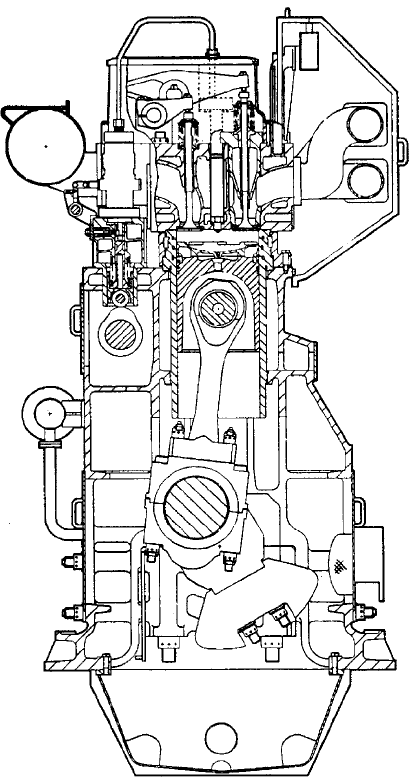
600 rev/min. The design matured from the K-engine of the 1950s, one of the
first large medium-speed engines in the world, which in its previous Mark 2
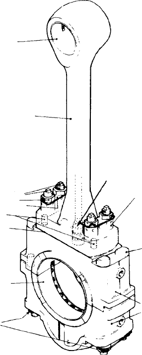
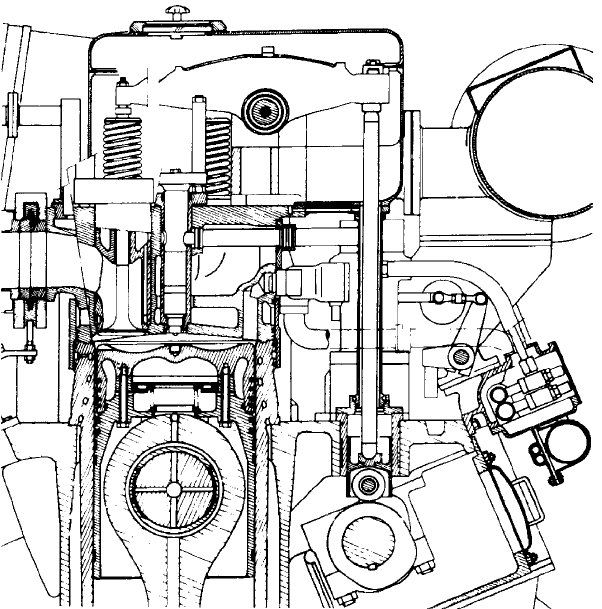
form featured a 381 mm bore (Figure 28.14). The connecting rod assembly of a
Mark 3 engine is shown in Figure 28.15.
The MB430 design also exploited some concepts introduced for the
MB275 series in 1979. This 275 mm bore/305 mm stroke engine was available
in six and eight in-line and V12- and 16-cylinder versions covering a power
range up to 5070 kW at 1000 rev/min.
Mirrlees Blackstone 731
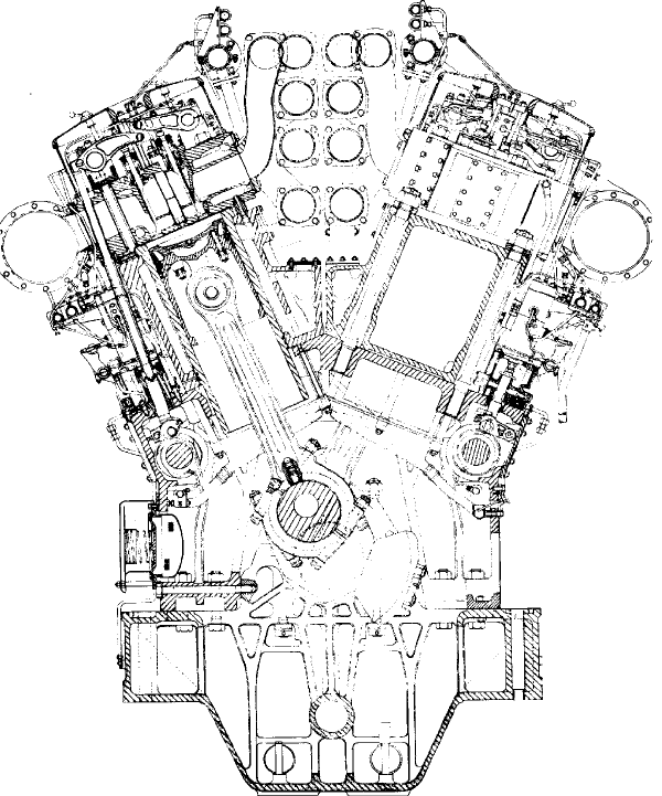
FigurE 28.13 Mirrlees Blackstone MB430 design
732 Other Medium-Speed Engines
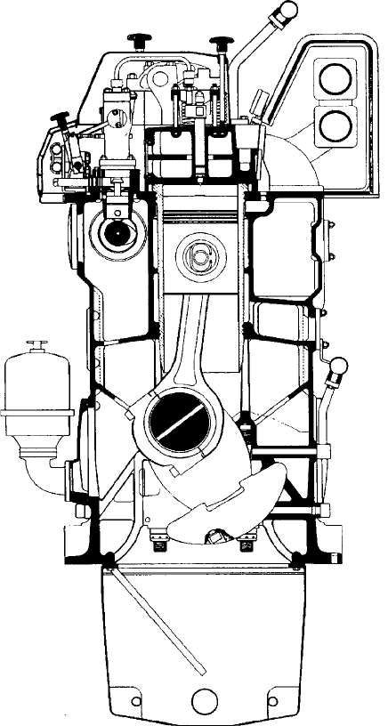
Lower power requirements were served by Mirrlees Blackstone’s 222 mm
bore/292 mm stroke ESL series (Figure 28.16) whose upper output limit was
doubled in 1986 by V12- and V16-cylinder models, the latter developing
2985 kW at 1000 rev/min. The programme also embraced five, six, eight and
nine in-line cylinder models.
The V-versions tapped the pedigree of the former E range but incorporated
several interesting features, including an underslung crankshaft and a belt drive
for the lubricating oil and water pumps. The V-models have a 45° cylinder con-
figuration, deep main bearing caps, side bolts for added structural stiffness and
a central air intake. A simplified rocker arrangement operates four valves (two
inlet and two exhaust) through two levers and bridge pieces enclosed within
an aluminium cover. The valve gear is actuated by side-loaded camshafts
driven from the flywheel end through nitride-hardened gears. The three-piece
FigurE 28.14 Cross-section of Mirrlees Blackstone KV Major Mk 2 engine
construction of the connecting rod allows piston withdrawal without disturbing
the large end bearing.
A pulley and flat belt arrangement for the service pumps, mounted on the
engine front, represented a departure from the traditional gear drive used by
most enginebuilders. Its adoption was considered beneficial in lower produc-
tion costs, pump speed flexibility, easier installation and maintenance, and
weight and power savings. The belt comprises a core of endless polyester cords
helically wound with a chrome leather friction face covering. A minimum belt
life of 10 000 h was anticipated.
MitSui
A major licensee of MAN Diesel in the production of MC/ME low-speed
engines, Mitsui also once offered its own 420 mm bore/450 mm stroke
medium-speed design whose last version was designated the L/V42MA series.
Mitsui 733
Large end
block
Connecting rod
foot valve
Large end bearing
half shell
Connecting rod shank
Small end bush
Palm end stud
Lock nut
Locking plate
Dowel
Palm end shim
Large end nut, lock
nut & locking plate
Large end
bolt
Palm end nut
FigurE 28.15 Mirrlees Blackstone K Major Mk 3 connecting rod assembly
734 Other Medium-Speed Engines
The launch of the Japanese group’s earlier venture in the four-stroke sector,
the 600 mm bore 60M design with a rating of 1120 kW/cylinder, unfortunately
coincided with the 1973 oil crisis which undermined its market.
The smaller bore L/V42M design, however, benefited from that ill-fated
project and became available in in-line and V-cylinder form with an output
per cylinder of 558 kW at 530 rev/min. The frame is in two parts, comprising a
welded steel crankcase structure made from cast sections and plate and a cast
iron cylinder housing held together with tie-bolts. The underslung crankshaft
bearings are secured by vertical and lateral bolts, all hydraulically tightened.
The designers sought a stress-free structure, controlling the lateral fit between
bearing keep and frame, for example, by tapered adjusting liners before tight-
ening to avoid stressing the frame unduly.
For the crankshaft bearings, Mitsui was able to keep within the stress
capacity of thin white metal (on a lead–bronze backing in the case of the
crankpins) with an overlay. While this is a function of the control of maximum
bearing pressures, it also means that damage to a bearing does not necessarily
lead to shaft damage.
The combustion area and cylinder head configuration can be appreciated
from Figure 28.17. Note the composite piston, bore-cooled cylinder liner,
three-deck head, caged exhaust valves and rigid high-pressure fuel line, as well
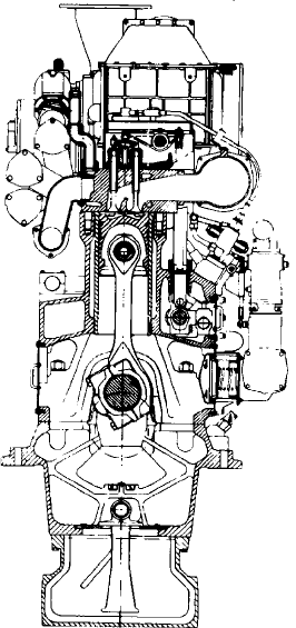
FigurE 28.16 Mirrlees Blackstone ESl Mk 2 design
as the camshaft bearing arrangement. In addition to the four compression rings
in the piston crown (the second is Ferrox-filled to improve running-in) there
are two conformable SOC rings at the top of the cast iron piston skirt and two
broad lead–bronze bands above the gudgeon and one below; these also assist
during the running-in phase.
A three-part marine-type connecting rod was selected with serrations at the
big end joint. The exhaust valve cage can be removed easily by taking out the
pushrod and lifting clear the rocker. Rotators are applied on the exhaust valves,
and guide vanes are formed in the inlet passages of the head to foster swirl in
the charge air. A mist catcher is installed after the intercooler to reduce the
water loading of the charge air in humid ambient conditions.
The fuel injector sleeve is provided with small water passages at the seat.
These passages communicate with the cylinder head water passages and foster
a convection flow which gives adequate cooling to the nozzle for operation on
all fuels without the complication of water cooling the nozzles.
Subsequent refinements led to the Mitsui L/V42MA design with an output
raised to 625 kW/cylinder at 600 rev/min, allowing 6L- to V18-cylinder models
to cover a power band up to 11 250 kW.
Mitsui 735
FigurE 28.17 Cross-section through cylinder head and piston of Mitsui 42M engine
736 Other Medium-Speed Engines
niigAtA
A wide range of own-design high- and medium-speed engines from Niigata
Engineering of Japan was supplemented by licences to build SEMT-Pielstick
PA and PC series and MAN B&W Holeby 23/30 and 28/32 series engines.
Niigata’s own MG (Marine Geared) medium-speed programme embraces
designs with 190 mm, 220 mm, 250 mm, 260 mm, 280 mm, 320 mm, 340 mm,
400 mm, 410 mm and 460 mm bore sizes; the high-performance FX series
includes 165 mm and 260 mm bore versions. (See Chapter 30 for Niigata high-
speed engines.)
Its largest medium-speed engine, the MG46HX, is a 460 mm bore/600 mm
stroke design with an output per cylinder of 823 kW at 450 rev/min and the
capability to operate on 700 cSt fuel. Power demands up to 13 180 kW are met
by 6/8L and V12/16-cylinder models, the targeted propulsion plant applica-
tions including medium-to-large ferries, container ships and RoRo freight ves-
sels. The crankcase is built as a box structure to secure rigidity in handling a
maximum combustion pressure of 180 bar; engine noise and vibration levels
are also claimed to be low. Easier maintenance was addressed by simplified
component designs and hydraulic tools.
Niigata also developed the HLX series, which embraces 220 mm, 280 mm
and 340 mm bore sizes covering a power band from 1392 kW to just under
10 000 kW from in-line and V-cylinder models.
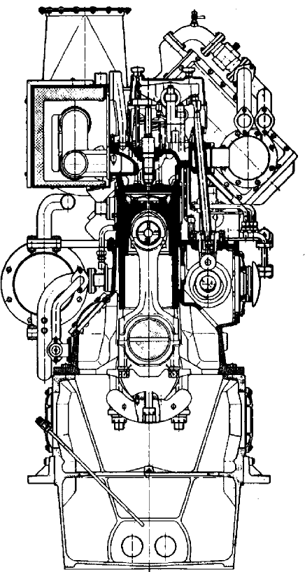
nOhAB
The Nohab engine business was acquired by Wärtsilä, which focused on the
Swedish designer’s Nohab 25 series before phasing out the programme.
This 250 mm bore/300 mm stroke design was offered in six in-line and
V12- and 16-cylinder versions covering output demands up to 3680 kW at
720/750/825/900 rev/min and 1000 rev/min for auxiliary and propulsion plant
markets. The engine proved particularly popular in the offshore power arena.
A cross-section of the 6R25 model is shown in Figure 28.18.
SKl
Four-stroke engines in a number of bore sizes—160 mm, 200 mm, 240 mm and
320 mm—were produced by SKL whose pedigree dates back to 1905 when the
Magdeburg, German-based company’s forerunner (Lokomobilenfabrik R. Wolf),
took out a licence to build diesel engines. SKL Motor was taken over in 2008
by MTU Friedrichshafen, which has invested in a remanufacturing centre for
its own high-speed engines.
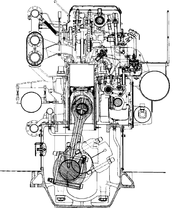
SKL Motor’s medium-speed engine programme remains in production,
including the VDS 29/24 AL series for propulsion and genset duties which is
offered in six, eight and nine in-line cylinder versions to cover an output range
up to 2350 kW at 750/900 rev/min and 1000 rev/min. Its brake mean effective
pressure rating is 23.9 bar.
The 240 mm bore/290 mm stroke design (Figure 28.19) is based on a rigid
nodular cast iron cylinder block housing a suspended crankshaft. The block is
free of cooling water thanks to a special cylinder liner design which incorpo-
rates a raised, rigid and separately cooled collar; this feature protects against
corrosion and deposits, and reduces maintenance costs. The alloyed flake-
graphite cast iron liner benefits from all-round nitration to enhance its wear
resistance. Four cylinder head screws with long anti-fatigue shafts transmit
forces via intermediate walls and ribs in the block and via the main bearing
screws to the main bearing covers.
SKl 737
FigurE 28.18 Wärtsilä nohab r25 design
738 Other Medium-Speed Engines
A deformation-resistant bedplate forms the bottom of the housing and can,
in appropriately extended form, also serve as the mounting for an alternator.
The camshaft is carried by bearings in the cylinder block and driven by gear-
ing at the opposite end to the coupling. A hardened and tempered crankshaft,
upset forged from C-steel, is supported by interchangeable thin-walled multi-
layer slide bearings. A viscosity-type torsional vibration damper is arranged
at the free end of the crankshaft. The control gear and vibration damper flange
are attached to the crankshaft by a cone interference fitting and hydraulically
mounted. Up to 60 per cent of the rated output can be taken off at the opposite
FigurE 28.19 SKl’s VDS 29/24 Al design
end to the coupling. Also hardened and tempered and forged from alloyed C-
steel, the connecting rod is divided horizontally at its large end and supported
by interchangeable thin-walled multi-layer slide bearings.
The composite piston consists of a steel crown and aluminium alloy skirt,
bolted from the top and supplied with cooling oil through a longitudinal bore
in the connecting rod. The ring pack comprises three compression and one oil
scraper rings with chromium-plated surfaces.
Four necked-down bolts secure the cylinder head to the block, the head
incorporating two inlet and two exhaust valves. Engines destined for heavy
fuel burning are equipped with turning devices for the exhaust valves. The hard
facing of the valve seat surfaces in combination with the cooling of the exhaust
valve seat rings, mounted in the cylinder head, fosters extended operational
lifetimes for the components. The fuel injection valve is located in the centre
of the cylinder head. The valve drive (lubricated by pressure oil and arranged
in an oil-tight enclosure) is effected from the camshaft via roller tappets, push-
rods and forked rockers.
Turbocharging is based on a three-pulse system with a claimed maximum
efficiency of at least 64 per cent. A compressor washing device and, for heavy
fuel service, a turbine washing device are specified to reduce maintenance
demands.
Fuel is injected by individual top-mounted pumps at maximum injection
pressures of 1400 bar-plus which, in conjunction with an optimized cam geom-
etry, ensures a short combustion time. Ideal combustion with minimal noxious
emissions is further pursued by short injection pipes (incorporating double
walls for safety) and optimized nozzle spray angles and injection hole diam-
eters. In heavy fuel engines the injection nozzle is continuously cooled with
lubricating oil from the engine circuit, and fuel pipings sheathed with heating
piping are isolated. The quantity of fuel injected is controlled by a mechani-
cal–hydraulic speed governor via a compound control rod arrangement.
Engine cooling is effected by two circuits. The cylinder liner, head and
turbocharger are cooled via a high-temperature circuit while a low-tempera-
ture circuit serves the oil and charge air cooler as well as the heat exchanger
(water). Both circuits are designed for the direct fitting of centrifugal pumps.
Engine lubrication is carried out by a pressure circulation system served by a
lubricating oil pump, filter and cooler mounted on the engine. The system also
supplies the piston with cooling oil.
StOrK-WErKSpOOr DiESEl
Formed in 1954 by the merger of Stork and Werkspoor, along with other inter-
ests in the Dutch enginebuilding industry, Stork-Werkspoor Diesel (SWD) was
acquired in 1989 by the Finland-based multinational Wärtsilä Diesel group,
now the Wärtsilä Corporation. SWD’s own-design medium-speed engines
were gradually phased out of the production programme and replaced by the
Wärtsilä 26 and 38 series (Chapter 27), largely designed by SWD staff and
Stork-Werkspoor Diesel 739
740 Other Medium-Speed Engines
subsequently manufactured in Zwolle, The Netherlands. These models were
later assigned for production by Wärtsilä Italia in Trieste.
Not long after its formation, SWD decided to develop a high-powered
medium-speed engine to contest diverse coastal and deep-sea propulsion are-
nas, the resulting TM410 series appearing on the market in the later 1960s.
The 410 mm bore/470 mm stroke design (Figure 28.20) was uprated a number
of times in its career to a level of 564 kW/cylinder at 600 rev/min, the series
embracing six, eight and nine in-line and V12-, 16-, 18- and 20-cylinder
versions.
A scaled-up version—the TM620 series—was introduced in the mid-1970s
to complement the TM410, the 620 mm bore/660 mm stroke design enjoying a
status for many years as the world’s largest and most powerful medium-speed
engine (Figure 28.21). Examples of both types—in in-line and V-cylinder
form—remain at sea (Figure 28.22).
FigurE 28.20 Cross-section of in-line SWD tM410 engine