Woodyard D. (ed.) Pounders Marine diesel engines and Gas Turbines
Подождите немного. Документ загружается.

700 Wärtsilä
and consequently lower mechanical load; reduced delay in the pre-burning phase,
which lowers peak pressure and temperature and hence curbs NOx emission for-
mation; improved starting ability; and increased thermal efficiency.
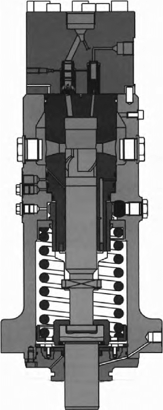
The mono-element injection pump (Figure 27.26) was designed to serve the
twin injection system. A constant pressure relief valve eliminates the risk of
cavitation erosion by maintaining a residual pressure at a safe level over the full
operating field. A drained and sealed-off compartment between the pump and
tappet prevents leakage fuel from mixing with lubricating oil. The pre-calibrated
pumps are interchangeable.
Figure 27.26 Wärtsilä 46 engine fuel pump designed to serve the original twin
injection system
Fuel system pipes and main components are located in a hot box to secure
safety at high preheating temperatures; fuel pipes outside the hot box are also
carefully shielded. The fuel feed pipes on the engine are equipped with pres-
sure pulsation dampers. Any fuel leakage from pipes, injection valves and
pumps is collected in a closed piping system which keeps the hot box and the
engine dry and clean.
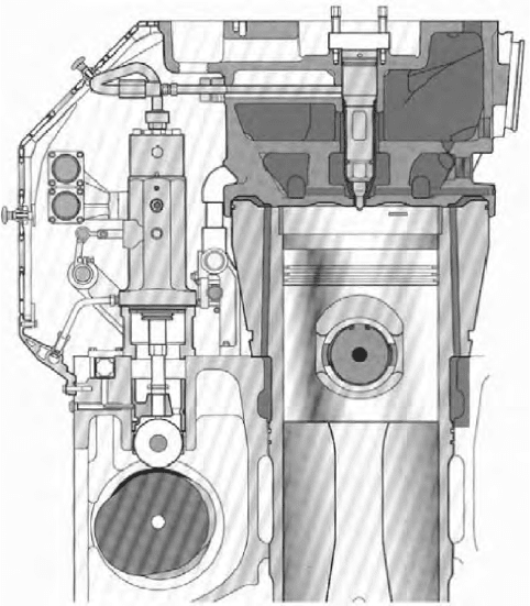
The twin injection system was later replaced by a single injection configu-
ration as higher pressure traditional layouts became available (Figure 27.27).
Spex Turbocharging
Swirl-Ex turbocharging—a constant pressure system with an in-built diffuser—
was specified for early Wärtsilä 46 engines. It demonstrated high efficiency
but service experience showed up a disadvantage due to the large volume in
the exhaust pipe which made the load pickup slower than the standard in other
Wärtsilä engines. A faster turbocharging system based on a single pipe with a
much smaller volume was therefore developed, resulting in the Spex system.
This offers a swift load pickup and almost the same efficiency at high load as
the Swirl-Ex system.
The aim of an exhaust system is to transfer the energy released from the cylin-
der, after the exhaust valve has opened, to the turbine of the turbocharger in the most
effective way. This could easily be done by making the pipes as short as possible
Figure 27.27 Single injection system for later Wärtsilä 46 engines
Wärtsilä 46 701
702 Wärtsilä
and the areas wide without restrictions. There are, however, other parameters that
must be taken into account, such as uniform scavenging. Since all the cylinders
are connected to the common system there is an obvious risk that a pulse com-
ing from one cylinder at the beginning of the blow-down phase disturbs the scav-
enging of another cylinder. To avoid this, the design has to be suited to all the pos-
sible cylinder configurations and speed ranges that the engine type will cover.
Another parameter affecting scavenging is the pressure drop between inlet
and exhaust manifolds. The higher the pressure difference, the better resistance
the cylinder has against the disturbing pulses in the exhaust manifold; the pres-
sure difference is largely a function of the turbocharger efficiency. Thus there
are many parameters affecting the performance of the exhaust system, and the
final design is a compromise between various factors.
Turbocharging of the W46 engine is now optimized for the given applica-
tion exploiting the Spex system as standard (original Swirl-Ex engine installa-
tions in service were reconfigured). For special applications, where low load
running accounts for a large proportion of the total operating time, a three-
pulse system is also offered for appropriate cylinder numbers. Pulse charging is
reportedly excellent at partial load operation and for fast load response, while
Spex charging is said to be excellent at high and steady loads, with the load
response remaining good. Spex is based on an exhaust gas system that com-
bines the advantages of both pulse and constant pressure charging. Compared
with a constant pressure system, the ejector effect of the gas pulses provides
better turbine efficiency at partial loads. Very small deviations in the scaveng-
ing between the cylinders result in an even exhaust gas temperature.
Modular-built exhaust gas systems on the W46 engine are designed to han-
dle high-pressure ratios and pulse levels while being elastic enough to cope
with thermal expansion in the system. Exhaust wastegate, air bypass and air
waste gate arrangements can be specified to satisfy specific operating require-
ments, such as load response or partial load performance.
A load-dependent cooling water system is used for the LT water circuit. At
low load the water temperature is elevated by transferring heat from the lubri-
cating oil to the charge air. This eliminates the risk of cold corrosion in the
combustion space and also improves the ability to burn fuels of low ignition
quality at low loads. The HT cooling water system operates constantly at a HT
to make the temperature fluctuations in the cylinder components as small as
possible and to prevent corrosion due to undercooling. The charge air cooler is
split into HT and LT sections to maximize heat recovery. Engine-driven pumps
are available as an option.
A wet or dry sump lubricating oil system can be specified. On its way to the
engine the oil passes through a full flow automatic filter unit and a safety filter
for final protection. A small proportion of the flow is diverted to a centrifugal
filter which acts as a lubricating oil condition indicator and warns the operator
of excessively dirty oil and wear. Both the safety filter and the indicator filter
are designed for cleaning while the engine is running. An engine-driven lubri-
cating oil pump can be provided optionally.
Wärtsilä 46F
Market drivers, particularly environmental regulations, dictated not just an
upgrade but the development of a new 46 engine design based on the origi-
nal cylinder dimensions but exploiting novel solutions for key components
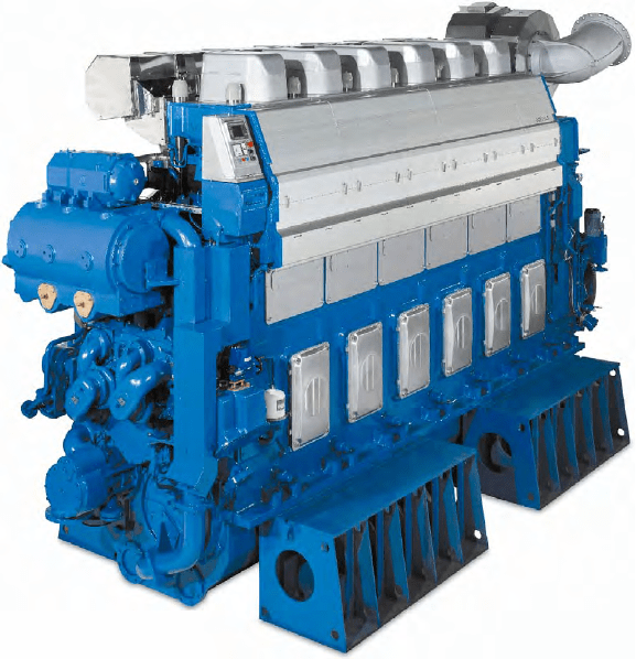
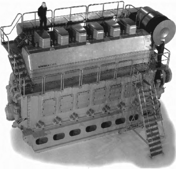
and systems (Figure 27.28). The resulting 46F engine, launched in 2004, was
described as more powerful without compromising reliability, and offering
attractive power-to-weight and space ratios, competitive fuel and lube oil con-
sumptions, and low emissions regardless of fuel quality.
The original 46 engine series remained on offer alongside the 46F pro-
gramme, which covers a power band from 7200 kW to 14 400 kW with six-to-
nine in-line and V12-cylinder models. (A V20-cylinder version introduced in
2007 with an output of 23 000 kW was initially intended for land-based power
installations.) Installation, operational and maintenance benefits flowed from
the increased specific rating since an engine with fewer cylinders (say, seven
instead of nine) can be specified to deliver the same power. More compact
machinery spaces and easier installation procedures are further fostered by
built-on support system modules.
Figure 27.28 An in-line six-cylinder version of the 46F engine
Wärtsilä 46F 703
704 Wärtsilä
A higher specific output (1250 kW/cylinder) was achieved by increasing
engine speed (from 500/514 to 600 rev/min) instead of mean effective pressure
(25.9 bar) and applying the latest developments in turbocharging to make wider
use of the Miller valve timing concept. Under full load operation early closure
of the inlet valves fosters a low effective compression ratio and hence com-
paratively low temperatures at the end of the compression stroke. The charge
air, both somewhat expanded and cooled on its way through the receiver into
the cylinders, contributes to creating the initial conditions for environment-
friendly combustion: a low global temperature that is still high enough to guar-
antee reliable and stable ignition of the fuel–air mixture.
An optional variable inlet valve closure (VIC) facility—first designed for
the Sulzer ZA40S medium-speed engine—controls the closing time of the inlet
valves. With VIC it is possible to arrange an early Miller cycle or remove it
completely, control being possible while the engine is operating.
Wärtsilä’s common rail fuel injection system, a standard fitment on the 46F
engine, maximizes the scope for adjusting the injection process to the prevail-
ing operating conditions, fuel characteristics and emission limits (see Chapter
8). The engine is optionally offered with a conventional fuel injection system
based on twin-plunger injection pumps (see section Wärtsilä 64).
In the CR system updated for the W46F engine the high-pressure pumps
are mounted on a tappet housing module which is interconnected between
cylinders. The module carries all low-pressure fuel system supply and return,
including drains and sealing oil systems, fostering a low level of piping den-
sity. The pumps are driven by a camshaft incorporating two cam lobes, with
one pump assigned to every two cylinders of the engine; pump filling is suc-
tion controlled by linear solenoid valves. The suction control valve is built as a
module together with the solenoid.
Each pump primarily feeds into an accumulator, each of which in turn
serves two injectors. The accumulators are interlinked by small bore piping to
form a CR. The piping between the accumulators undertakes three functions:
equalization of the pressure; reduction of pressure pulsations; and system con-
nectivity during engine warm-up circulation with heavy fuel oil.
Fuel flow to the two-stage injector’s nozzle is controlled by a shuttle valve
actuated by control oil which, in turn, is controlled by a solenoid valve. The con-
trol oil pump is engine driven for easy black start. Nozzle needle movement is
controlled by the fuel pressure in the nozzle gallery, and pressure acting on the
press-down piston which, under certain safety conditions, keeps the nozzle shut.
A Spex system is standard, with options of exhaust gas waste gate or air bypass
depending on the application. The turbocharger can be located at either the free or
the driving end of the engine, transversal alignment allowing the exhaust gas outlet
to be inclined in the longitudinal direction. The charge air receiver is integrated in
the engine block, and the two-stage self-supporting charge air cooler comprises
separate HT and LT water sections (an advantage for heat recovery applications).
A continuous bearing temperature monitoring system covers not only the
main bearings (as in some earlier engines) but for the first time also the big
end bearings, the latter benefiting from a new installation system patented by
Wärtsilä. The bearing temperatures are recorded at a point roughly half-way
between the crank webs and a few millimetres beneath the crankpin surface. A
stationary antenna mounted on the intermediate wall in the crankcase records
the bearing pin temperature every time the crank throw passes the registration
unit (several times a second). The temperature pickup is passive and requires
no electrical supply. Kongsberg Maritime’s Sentry wireless temperature moni-
toring system, specified as standard for the big end bearings, can be linked to
Wärtsilä’s condition-based maintenance system.
Nodular cast iron was retained for the engine block but the new compo-
nent, with an attractive stiffness-to-weight ratio, is both lower and lighter than
that of the 46 engine. The rigid and self-supporting block is designed for resil-
ient mounting applications, hydraulically tightened main bearing screws and
side screws, and to provide easy internal access for service personnel.
WärTSiLä 64
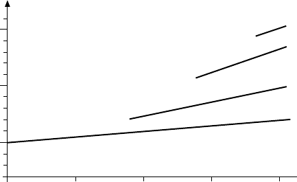
The most powerful medium-speed design ever brought to the market—and
reportedly the first to exceed the 50 per cent thermal efficiency barrier (Figure
27.29)—the Wärtsilä 64 engine was prototype-tested in six-cylinder form in
September 1996 (Figure 27.30). Production models became available from
autumn 1997 and have since logged propulsion applications in container ships,
multipurpose cargo vessels and chemical/product tankers. The engines are
assigned for manufacture by Wärtsilä Italia in Trieste.
A
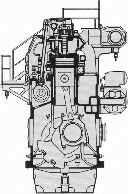
nominal output of 2010 kW/cylinder at 333 rev/min was originally quoted
for the 640 mm bore/900 mm stroke in-line cylinder design on a mean effective
pressure of 25 bar and a maximum cylinder pressure of 190 bar (Figure 27.31).
The rating was later raised to 2150 kW/cylinder with meps up to 27.2 bar.
Power demands up to 17 200 kW can now be met by a programme of six-,
seven- and eight-cylinder in-line models, the 9L- and V12-cylinder versions in
1960 1970 1980 1990 2000
20 Bore
32 Bore
46 Bore
64 Bore
%
50
40
Figure 27.29 rise in thermal eciency of successive Wärtsilä medium-speed
engine designs
Wärtsilä 64 705
706 Wärtsilä
the original programme having been dropped. The V-engine had the same bore
but a shorter stroke (770 mm) and lower specific power rating (1940 kW/cyl-
inder at 400–428 rev/min on an mep of 22–23.5 bar) than the in-line design.
Performance was boosted by a high-efficiency TPL80E turbocharger, one of
ABB Turbo Systems’ latest TPL series (see Chapter 7).
Reliability is sought from traditional Wärtsilä solutions, notably a pressure-
lubricated piston skirt, large bearings with thick oil films, thick collar cylinder
liners fitted with an anti-polishing ring, high fuel injection pressures for opti-
mized combustion, and camshafts with high torque capacity and low Hertzian
pressures. Easier installation is addressed by built-on cooling water pumps and
lubricating oil system (including automatic filters). Simplicity of maintenance
is reflected in a maximum overhaul time of 3 h for the ‘strategic’ components
(main and big end bearings, pistons, cylinder heads and injection pumps)
thanks to design measures and special tools.
W64 engine Details
Engine block: Wärtsilä suggests that nodular cast iron is the natural choice
for modern engine blocks because of its strength and stiffness properties and
the freedom that casting offers. Optimum use was made of current foundry
Figure 27.30 The Wärtsilä 64 engine is the world’s largest and most powerful
medium-speed design
technology to integrate most oil and water channels, resulting in a virtually
pipe-free engine with a clean outer exterior. Resilient mounting, now common,
calls for a stiff engine frame; integrated channels designed with this in mind
thus serve a dual purpose.
Crankshaft and bearings: advances in combustion development require a
crank gear which can operate reliably at high cylinder pressures. The crank-
shaft must be robust and the specific bearing loads kept at an acceptable level;
this is achieved by optimizing the crank throw dimensions and fillets. The spe-
cific bearing loads are conservative and the cylinder spacing (important for the
overall length of the engine) is minimized. Apart from low bearing loads, the
Figure 27.31 Cross-section of Wärtsilä 64 design
Wärtsilä 64 707
708 Wärtsilä
other crucial factor for safe bearing operation is oil film thickness. Ample film
thicknesses in the main bearings are ensured by optimized balancing of rota-
tional masses and in the big end bearing by ungrooved bearing surfaces in the
critical areas. All these features ensure a free choice of the most appropriate
bearing material. The other thick-pad bearing technology concepts proven on
the Wärtsilä 46 engine (see p. 698) are also applied.
Piston and rings: a rigid composite piston with a steel crown and nodu-
lar cast iron skirt has been adopted for highly rated diesel engines for years to
secure reliability in a high cylinder pressure and combustion temperature envi-
ronment. Wärtsilä’s patented skirt lubrication is applied to minimize frictional
losses and ensure appropriate lubrication of piston rings and skirt. Each ring of
the three-ring pack is dimensioned and profiled for a specific task. The pres-
sure balance above and below each ring is crucial in avoiding carbon depos-
its in the ring grooves of a heavy fuel engine. Experience has shown that this
effect is most likely achieved with a three-ring pack, Wärtsilä reports. Another
factor favouring a three-ring pack is that most frictional losses in a reciprocat-
ing combustion engine originate from the rings. An extended lifetime is sought
from the piston ring pack and ring grooves through wear-resistant coating and
groove treatment (Figure 27.32).
Cylinder liner and anti-polishing ring: the thick high-collar type liner is
designed with the stiffness necessary to withstand both pre-tension forces and
combustion pressures with virtually no deformation. Its temperature is controlled
by bore cooling of the upper part of the collar to achieve a low thermal load and
Induction
Cr-plated
Cr-ceramic
Hardened
Cr-ceramic
Figure 27.32 Three-ring pack for Wärtsilä 64 engine piston; note the anti-polishing
ring incorporated in the upper cylinder liner (top right)
avoid sulphuric acid corrosion. The cooling water is distributed around the liners
with simple water distribution rings at the lower end of the collar. At its upper
end the liner is fitted with an anti-polishing ring to eliminate bore polishing and
reduce lube oil consumption. The ring’s function is to calibrate the carbon depos-
its formed on the piston top land to a thickness small enough to prevent any con-
tact between the liner wall and the deposits at any piston position. When there
is no contact between liner and piston top land deposits, no oil can be scraped
upwards by the piston; at the same time, liner wear is also significantly reduced.
Connecting rod: a three-piece rod with all highly stressed surfaces machined
is the safest design for engines of this size intended for continuous operation at
high combustion pressures, according to Wärtsilä. For easy maintenance and
accessibility the upper joint face is placed right on top of the big end bearing
housing. A special hydraulic tool was developed for simultaneous tensioning of
all four screws. An intermediate plate with a special surface treatment is arranged
between the main parts to eliminate any risk of wear in the contact surfaces.
Cylinder head: high reliability and ease of maintenance were sought from
a stiff cone/box-like design able to cope with the high combustion pressure and
secure both cylinder liner roundness and even contact between the exhaust valves
and their seats. The head design is based on the four-screw concept developed by
Wärtsilä and applied for over 20 years. Such a design also provides the freedom
needed for designing inlet and exhaust ports with minimal flow losses. The port
design was optimized using computational fluid dynamics (CFD) analysis in
conjunction with full-scale flow measurements. Wärtsilä’s extensive heavy fuel-
burning experience contributed to the exhaust valve design, the basic criterion
for which is correct temperature; this is achieved by carefully controlled cooling
and a separate seat cooling circuit to secure long lifetimes for valves and seats.
Fuel injection system: the split-pump technology first introduced on the W64
engine offers advantages in terms of operating flexibility, mechanical strength
and cost-effectiveness. Fuel injection timing can be freely adjusted independently
of the injected quantity, and tuning of the injection parameters according to the
engine’s operational conditions improves engine performance and reduces exhaust
emissions. Smaller closed-type pump elements—derived from high volume pro-
duction of smaller engines—reduce mechanical stresses and enhance reliability,
while lower loads on rollers, tappets and cams improve pump drive reliability.
This new solution was dictated when injection pump manufacturers sug-
gested that for such a large medium-speed engine it would be very difficult to
produce pump plungers of the size and accuracy required to secure the reliabil-
ity associated with smaller engine designs. Since the output of the Wärtsilä 64
is approximately double that of the established Wärtsilä 46, it was decided to
use two plungers (each of roughly W46 size) per engine cylinder.
The two plungers have slightly different functions (Figure 27.33). Both pump
fuel at each stroke and are connected to the same line, from where fuel is led to
the nozzle via a single high-pressure line. Although both plungers pump the fuel
in a similar way, only one of them needs to be controlled to adjust the fuel quan-
tity. This made it possible to reserve the other plunger for another task: turning
Wärtsilä 64 709