Yu W., LaBoube R.A. Cold-Formed Steel Design
Подождите немного. Документ загружается.


BOLTED CONNECTIONS 285
Cornell University in the 1950s to study the type of failure
caused by shearing of the bolt.
8.37,8.38
It was found that
the shear–tension strength ratio is independent of the bolt
diameter, and the ratios are equal to about 0.62 and 0.72
for double-shear and single-shear tests, respectively. In
view of the fact that the failure by shearing of the bolt
is more sudden than that in the sheets being connected,
a conservative shear-to-tension ratio of 0.6 has been used
in the past for both double- and single-shear conditions
in the development of design provisions, even though the
extremes of test values ranged from 0.52 to 1.0; that
is, the type of failure by shearing of the bolt occurs
at a strength equal to 0.6 times the tensile strength of
the bolt.
8.4.2 AISI Design Criteria for Bolted Connections
Based upon the results of tests summarized in Section 8.4.1
and past design experience, Section E3 and Appendix A of
the 2007 edition of the AISI North American Specification
includes a number of requirements for the design of bolted
connections in the United States and Mexico and are
summarized herein. Section E3 and Appendix B contain
the provisions for Canada.
8.4.2.1 Thickness Limitations On the basis of the same
reasons discussed in Section 8.3.2.1 for the design of
welded connections, Section E3 of the Specification is
applicable only to the design of bolted connections for cold-
formed steel members that are less than
3
16
in. (4.8 mm) in
thickness. For materials not less than
3
16
in. (4.8 mm), the
AISC specification
1.411
should be used for the design of
bolted connections in cold-formed steel structures.
8.4.2.2 M aterials Prior to 1980, the AISI design provi-
sions concerning the allowable shear stresses for mechan-
ical fasteners were limited to A307 and A325 bolts. Because
the maximum thickness for cold-formed steel members was
increased in 1977 from
1
2
in. (12.7 mm) to 1 in. (25.4 mm),
other high-strength bolts, such as A354, A449, and A490
bolts, were added to the 1980 specification for bolted
connections.
In view of the fact that A325 and A490 bolts are available
only for a diameter of
1
2
in. (12.7 mm) and larger, whenever
smaller bolts [less than
1
2
in. (12.7 mm) in diameter] are
required in a design, A449 and A354 Grade BD bolts
should be used as equivalents of A325 and A490 bolts,
respectively.
For other types of fasteners, which are not listed in
Section E3 of the AISI North American Specification, draw-
ings should indicate clearly the type and size of fasteners
to be employed and the design force.
8.4.2.3 Bolt Installation The requirement for bolt instal-
lation was added to the AISI Specification since 1980
to ensure that bolts are properly tightened according to
acceptable practice. Because the required pretension in bolts
usually varies with the types of connected part, fasteners,
applied loads, and applications, no specific provisions are
provided in the AISI North American Specification for
installation.
The effect of torques on the strength of bolted connec-
tions has been studied in the past and was reported in
Ref. 8.45.
8.4.2.4 Maximum Sizes of Bolt Holes The 1986 and
the 1996 editions of the AISI Specification include the
maximum sizes of standard holes, oversized holes, short-
slotted holes, and long-slotted holes, as shown in Table 8.4.
Standard holes should be used in bolted connections, except
that oversized and slotted holes may be used as approved
by the designer. Additional requirements are given in the
AISI North American Specification for the use of oversized
and slotted holes.
8.4.2.5 Shear, Spacing, and Edge Distance in Line of
Stress According to Section E3.1 of the AISI North
American Specification, the nominal shear strength, P
n
,of
the connected part as affected by spacing and edge distance
in the direction of applied force shall be calculated as
follows:
P
n
= teF
u
(8.51)
(a) When F
u
/F
y
≥ 1.08:
= 2.0 (ASD)
φ = 0.70 (LRFD)
(b) When F
u
/F
y
< 1.08
= 2.22 (ASD)
φ = 0.60 (LRFD)
where P
n
= nominal resistance per bolt
e = distance measured in line of force from
center of standard hole to nearest edge of
adjacent hole or to end of connected part
t = thickness of thinnest connected part
F
u
= tensile strength of connected part
F
y
= yield stress of connected part
Equation (8.51) was derived from Eq. (8.45) in Section
8.4.1.1. The above design equation is the same as that used
in previous editions of the AISI specification, except that
the limiting F
u
/F
y
ratio was reduced in 1996 from 1.15
286 8 CONNECTIONS
to 1.08 for the consistency with the ductility requirement
prescribed in Section A3.3.1 of the Specification.
In addition to the above requirements, Section E3.1 of
the AISI North American Specification also includes the
following requirements concerning minimum spacing and
edge distance in the line of stress:
1. The minimum distance between centers of bolt holes
should not be less than 3d.
2. The distance from the center of any standard hole to
the end or other boundary of the connecting member
should not be less than 1
1
2
d.
3. For oversized and slotted holes, the distance between
edges of two adjacent holes and the distance measured
from the edge of the hole to the end or other boundary
of the connecting member in the line of stress should
not be less than the value of e − 0.5d
h
,inwhiche is
the required distance computed from Eq. (8.51) using
the applicable safety factor for ASD and resistance
factor for LRFD, and d
h
is the diameter of a standard
hole defined in Table 8.4. Also, the clear distance
between edges of two adjacent holes should not be
less than 2d and the distance between the edge of the
hole and the end of the member should not be less
than d.
8.4.2.6 Tensile Strength of Connected Parts at
Connection Prior to 1999, the tensile strength on
the net section of connected parts was determined in
accordance with Specification Section E3.2 in addition to
the requirements of Specification Section C2. In Section
E3.2, the nominal tensile strength on the net section of the
bolt connected parts was determined by the tensile strength
of steel F
u
and the ratios r and d/s. These design equations
represent the shear lag effect on the tensile capacity of flat
sheets with due consideration given to the use of washers
and the type of joints, either a single-shear lap joint or a
double-shear butt joint.
During recent years, research work has been conducted
by Holcomb, LaBoube, and Yu at the University of
Missouri-Rolla to study the effect of shear lag on the
tensile capacity of angles and channels as well as flat steel
sheets.
6.24,6.25
The same project included a limited study of
the behavior of bolted connections having staggered hole
patterns. It was found that when a staggered hole pattern
is involved the net area can be determined by a design
equation using the well-known parameter s
2
/4g.
Based on the research findings, the 2007 edition of the
AISI North American Specification includes the following
Specification Section E3.2 to deal with the determination of
the nominal tensile strength for (a) flat sheet connections not
having staggered hole patterns, (b) flat sheet connections
having staggered hole patterns, and (c) structural shapes
including angles and channels.
E3.2 Rupture in Net Section (Shear Lag)
The nominal tensile strength of a bolted member shall be
determined in accordance with Section C2. For rupture in the
effective net section of the connected part, the nominal tensile
strength, P
n
, shall be determined as follows:
1. For flat sheet connections not having staggered hole
patterns:
P
n
= A
n
F
t
(8.52)
a. When washers are provided under both the bolt head
and the nut:
F
t
=
1.0 +
3d
s
F
u
≤ F
u
(8.53a)
For multiple bolts in the line parallel to the force
F
t
= F
u
(8.53b)
For double shear
= 2.0 (ASD)
φ = 0.65 (LRFD)
For single shear
= 2.22 (ASD)
φ = 0.55 (LRFD)
b. When either washers are not provided under the bolt
head and the nut or only one washer is provided under
Table 8.4 Maximum Sizes of Bolt Holes
Nominal Standard Oversized Short-Slotted Long-Slotted
Bolt Hole Hole Hole Hole
Diameter, d Diameter, d Diameter, d Dimensions Dimensions
(in.) (in.) (in.) (in.) (in.)
<
1
2
d +
1
32
d +
1
16
(d +
1
32
) by (d +
1
4
)(d+
1
32
) by (2
1
2
d)
≥
1
2
d +
1
16
d +
1
8
(d +
1
16
) by (d +
1
4
)(d+
1
16
) by (2
1
2
d)
Note: 1in. = 25.4 mm.
BOLTED CONNECTIONS 287
either the bolt head or the nut:
F
t
= (2.5rd/s)F
u
≤ F
u
(8.54a)
For multiple bolts in the line parallel to the force
F
t
= F
u
(8.54b)
= 2.22 (ASD)
φ = 0.65 (LRFD)
where A
n
= net area of the connected part
s = sheet width divided by the number of bolt
holes in cross section being analyzed
F
u
= tensile strength of the connected part as
specified in Section A3.1 or A3.3.2
and d is defined in Section E3.1.
2. For flat sheet connections having staggered hole patterns:
P
n
= A
n
F
t
[Eq. (8.52)]
= 2.22 (ASD)
φ = 0.65 (LRFD)
where F
t
is determined by Eqs. (8.47) and (8.48) and
A
n
= 0.90
A
g
− n
b
d
h
t +
s
2
4g
t
(8.55)
Where A
g
= gross area of member
s = sheet width divided by number of bolt
holes in cross section being analyzed
(when evaluating F
t
)
s
= longitudinal center-to-center spacing of
any two consecutive holes
g = transverse center-to-center spacing between
fastener gage lines
n
b
= number of bolt holes in cross section being
analyzed
d
h
= diameter of standard hole
and t is defined in Section E3.1.
3. For other than a flat sheet:
P
n
= A
e
F
u
(8.56)
= 2.22 (ASD)
φ = 0.65 (LRFD)
where F
u
is the tensile strength of the connected part
as specified in Section A3.1 or A3.3.2 and A
e
= A
n
U,
is the effective net area with U = 1.0 for members
when the load is transmitted directly to all of the cross-
sectional elements. Otherwise, the reduction coefficient
U is determined as follows:
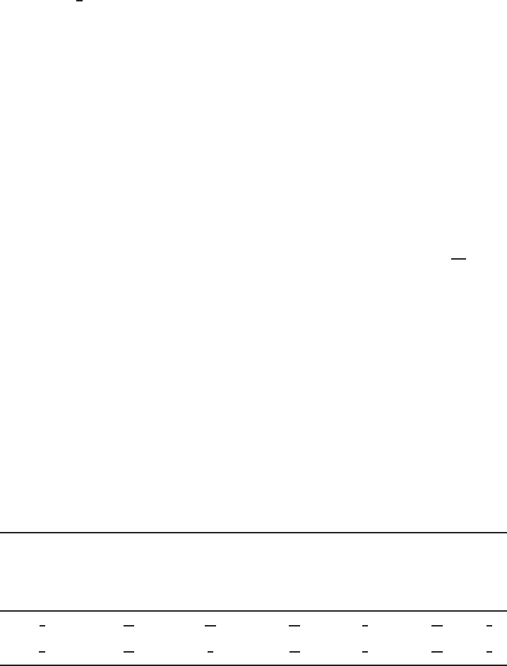
a. For angle members having two or more bolts in the
line of force:
U = 1.0 −
1.20 ¯x
L
< 0.9 (8.57a)
but U shall not be less than 0.4.
b. For channel members having two or more bolts in the
line of force:
U = 1.0 −
0.36 ¯x
L
< 0.9 (8.57b)
but U shall not be less than 0.5
where ¯x = distance from shear plane to centroid of
cross section (Fig. 8.29)
L = length of connection (Fig. 8.29)
The specification Eqs. (8.53) and (8.54) were
derived from Eqs. (8.48) and (8.50), respectively. See
Section 8.4.1.3 in this volume.
8.4.2.7 Bearing Strength between Bolts and Connected
Parts
a. Deformation Around the Bolt Holes Is Not a Design
Consideration. The nominal bearing strength (resistance)
of the connected sheet for each loaded bolt is given in
Section E3.3.1 of the Specification as
P
n
= Cm
f
dtF
u
(8.58)
= 2.50 (ASD)
φ =
0.60 (LRFD)
0.50 (LSD)
Figure 8.29 Determination of ¯x for sections using bolted connections.
1.346
288 8 CONNECTIONS
where C = bearing factor, determined in accordance
with Table 8.2
m
f
= modification factor for type of bearing
connection determined in accordance with
Table 8.3
d = nominal bolt diameter
t = uncoated sheet thickness
F
u
= tensile strength of sheet
b. Deformation Around the Bolt Holes Is a Design Consid-
eration. When the movement of the connection is critical
and the deformation around bolt holes is a design consid-
eration, nominal bearing strength should also be limited
by Eq. (8.47) according to Section E3.3.2 of the the 2007
edition of the Specification. For using Eqs. (8.47a) and
(8.47b), = 2.22 (for ASD), φ = 0.65 (for LRFD), and
φ = 0.55 (for LRFD). See Section 8.4.1.2 for additional
discussion.
8.4.2.8 Shear and Tension in Bolts Section E3.4 of
the AISI North American specification specifies that the
nominal bolt strength P
n
resulting from shear, tension, or
a combination of shear and tension shall be calculated as
follows:
P
n
= A
b
F (8.59)
where A
b
is the gross cross-sectional area of the bolt.
When bolts are subject to shear or tension, the nominal
stress F
n
is given in Table 8.5 by F
nv
for shear or F
nt
for
tension. The applicable values of and φ are also given
in the same table. When bolt tension is involved, the pull-
over strength of the connected sheet at the bolt head, nut,
or washer shall be considered. See Section 8.5.1.
When bolts are subject to a combination of shear and
tension,
F
nt
=
⎧
⎪
⎪
⎪
⎪
⎪
⎪
⎪
⎨
⎪
⎪
⎪
⎪
⎪
⎪
⎪
⎩
1.3F
nt
−
F
nt
F
nv
f
v
≤ F
nt
(for ASD method) (8.60a)
1.3F
nt
−
F
nt
φF
nv
f
v
≤ F
nt
(for LRFD method) (8.60b)
Table 8.5 Nominal Tensile and Shear Strength for Bolts
1.345
Tensile Strength Shear Strength
a
Factor Nominal Factor Nominal
of Safety Resistance Stress of Safety Resistance Stress
Factor φF
nt
Factor φF
nt
Description of Bolts (ASD) (LRFD) ksi MPa (ASD) (LRFD) ksi MPa
A307 bolts, Grade A,
1
4
in. (6.4 mm) ≤ d <
1
2
in. (12.7 mm)
2.25 0.75 40.5 279 2.4 0.65 24.0 165
A307 bolts, Grade A, d ≥
1
2
in. 2.25 45.0 310 27.0 186
A325 bolts, when threads are not excluded
from shear planes
2.0 90.0 621 54.0 372
A325 bolts, when threads are excluded from
shear planes
90.0 621 72.0 496
A354 Grade BD bolts,
1
4
in. ≤ d <
1
2
in., when
threads are not excluded from shear planes
101.0 696 59.0 407
A354 Grade BD bolts,
1
4
in. ≤ d <
1
2
in., when
threads are excluded from shear planes
101.0 696 90.0 621
A449 bolts,
1
4
in. ≤ d <
1
2
in., when threads
are not excluded from shear planes
81.0 558 47.0 324
A449 bolts,
1
4
in. ≤ d <
1
2
in., when threads
are excluded from shear planes
81.0 558 72.0 496
A490 bolts, when threads are not excluded
from shear planes
112.5 776 67.5 465
A490 bolts, when threads are excluded from
shear planes
112.5 776 90.0 621
a
Applies to bolts in holes as limited by Table 8.6. Washers or back-up plates shall be installed over long-slotted holes and the capacity
of connections using long slotted holes shall be determined by load tests in accordance with Chapter F.
BOLTED CONNECTIONS 289
where F
nt
= nominal tensile stress from Table 8.5
F
nt
= nominal shear stress from Table 8.5
f
v
= required shear stress
and and φ are also from Table 8.5. In addition, the
required shear stress shall not exceed the allowable shear
stress F
nv
/ (ASD) or the design shear stress φF
nv
(LRFD)
of the fastener.
In Table 8.5, the allowable shear and tension stresses
specified for A307, A325, and A490 bolts are approx-
imately the same as those permitted by the AISC
1.411
and the Research Council on Structural Connections for
bearing-type connections.
8.108
Slightly smaller allowable
shear stresses are used for A449 and A354 Grade BD bolts
with threads in the shear planes as compared with A325
and A490 bolts, respectively. Such smaller shear stresses
are used because the average ratio of the root area to the
gross area of the
1
4
- in. (6.4-mm) and
3
8
- in. (9.5-mm)
diameter bolts is 0.585, which is smaller than the average
ratio of 0.670 for the
1
2
- in. (12.7-mm) and 1-in. (25.4-mm)
diameter bolts. According to Ref. 1.159, these design values
provide safety factors ranging from 2.25 to 2.52 against the
shear failure of bolts.
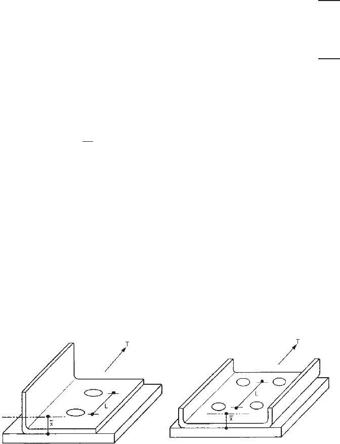
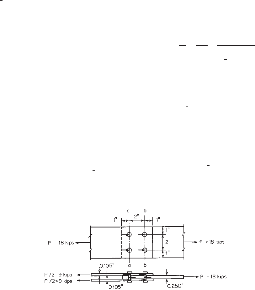
Example 8.4 Determine the allowable load for the bolted
connection shown in Fig. 8.30. Use four
1
2
-in.-diameter
A307 bolts with washers under the bolt head and nut. The
steel sheets are A570 Grade 33 steel (F
y
= 33 ksi and
F
u
= 52 ksi). Use ASD and LRFD methods. Assume that
the dead load–live load ratio is
1
5
and that the deformation
around bolt holes is not a design consideration.
SOLUTION
A. ASD Method
In the determination of the allowable load, consideration
should be given to the following items:
•
Shear, spacing, and edge distance in line of stress
(Section 8.4.2.5)
•
Tensile strength of connected parts at connection
(Section 8.4.2.6)
•
Bearing strength between bolts and connected parts
(Section 8.4.2.7)
•
Shear strength in bolts (Section 8.4.2.8)
1. Shear, Spacing, and Edge Distance in Line of Stress.
The distance from the center of a standard hole to the
nearest edge of an adjacent hole is
e
1
= 2 −
1
2
(d + 1/16) =2 −
1
2
(1/2 + 1/16)
= 1.72in.
Figure 8.30 Example 8.4.
The distance from the center of a standard hole to the
end of the plate in the line of stress is
e
2
= 1in.
Since e
2
<e
1
, the allowable load should be deter-
mined by e
2
.
Because F
u
/F
y
= 52/33 = 1.58 > 1.08, according
to Eq. (8.51), the allowable shear strength of the
connected sheet using four bolts can be computed as
P
1
=
4P
n
=
4(te
2
F
u
)
2.0
=
4(0.105 × 1 × 52)
2.0
= 10.92 kips
In addition, some other AISI requirements should be
checked on the basis of Section E3.1 of the AISI
North American Specification or Section 8.4.2.5 in
this volume as follows:
a. Distance between centers of bolt holes:
2in.>(3d = 1.5in.) OK
b. Distance from center of any standard hole to end
of plate:
1in.>(1
1
2
d = 0.75 in.) OK
2. Tensile Strength of Steel Sheets. Based on the AISI
design criteria, the allowable tensile strength of the
steel sheet can be determined under the following
considerations:
Based on Section C2 of the 2007 edition of the AISI
North American specification, the allowable tensile
strength can be computed as follows:
(i) For yielding [Eq. (6.2)],
T
a
=
T
n
t
=
A
g
F
y
1.67
=
(4.0 × 0.105)(33)
1.67
= 8.30 kips
290 8 CONNECTIONS
(ii) For fracture away from the connection [Eq.
(6.3)],
T
a
=
T
n
t
=
A
n
F
u
2.00
=
(4.0 × 0.105)(52)
2.00
= 10.92 kips
Use T
a
= 8.30 kips for the requirement of
Section C2 of the specification.
According to Sec. E.3.2(1) of the 2007 edition of
the specification for bolts with washers under the
bolt head and nut and for a single-shear connection
( = 2.22), the allowable tensile strength should
be determined by Eq. (8.52) as follows:
P
a
= P
n
/ = A
n
F
t
/
where
A
n
= [4 −2(1/2 + 1/16)](0.105) = 0.30 in.
2
F
t
= F
u
= 52 ksi
P
a
=
(0.30)(52)
2.22
= 7.03 kips
Since P
a
<T
a
,use(P
2
)
a
= 7.03 kips for section
a–a.
3. Bearing Strength between Bolts and Steel Sheets.
According to Section E3.3.1 of the 2007 edition of
the Specification, the allowable bearing strength per
bolt is
P
a
=
P
n
=
Cm
f
F
u
dt
2.50
d
t
= 4.76
Therefore C = 3.0 (Table 8.2) and m
f
= 1.0
(Table 8.3).
= (3)(1.0)(52)(
1
2
)(0.105) = 8.19 kips
P
a
=
8.19
2.50
= 3.27 kips
The allowable bearing strength for four bolts is
P
3
= 4 × 3.27 = 13.10 kips
4. Shear Strength in Bolts. From Table 8.5, the nominal
shear stress for the
1
2
-in.-diameter A307 bolts is
27 ksi and the gross area of the bolt is 0.196 in.
2
Therefore, the allowable shear strength for four bolts
is
P
4
=
4(A
b
F
nv
)
=
4(0.196)(27)
2.4
= 8.82 kips
Comparing P
1
, P
2
, P
3
,andP
4
, the allowable load
for the given bolted connection is 7.03 kips, which is
governed by the tensile strength of sheet A at section
a–a.
B. LRFD Method
For the LRFD method, the design considerations are the
same as for the ASD method. The design strength can be
calculated by applying some of the values used for the ASD
method.
1. Shear, Spacing, and Edge Distance in Line of Stress.
Using Eq. (8.51) for F
u
/F
y
> 1.08, the design shear
strength of a connected sheet using four bolts is
(φP
n
)
1
= 4(0.70)(te
2
F
u
) = 4(0.70)(0.105)(1)(52)
= 15.288 kips
2. Tensile Strength of Steel Sheets
Based on Section C2 of the 2007 edition of the speci-
fication, the design tensile strength of the connected
sheet is:
i. For yielding [Eq. (6.2)],
φ
t
T
n
= (φ
t
)(A
g
F
y
) = (0.90)(4 ×0.105)(33)
= 12.474 kips
ii. For fracture away from the connection [Eq.
(6.3)],
φ
t
T
n
= φ
t
(A
n
F
n
) = (0.75)(4 ×0.105)(52)
= 16.38 kips
Use φ
t
T
n
= 12.474 kips for the requirement of
Section C2 of the specification.
On the basis of Section E3.2(1) of 2007 edition
of the specification, the design tensile strength on
the net section of sheet A at section a–a can be
computed from Eq. (8.52) as follows:
φP
n
= φ(A
n
F
t
)
From the ASD method, A
n
= 0.30 in.
2
and F
t
=
52 ksi. Therefore,
φP
n
= (0.55)(0.30)(52) = 8.580 kips
Since φP
n
<φ
t
T
n
,use(φP
n
)
a
= 8.580 kips.
3. Bearing Strength between Bolts and Steel Sheets. The
nominal bearing strength per bolt is the same as calcu-
lated for the ASD method, that is, P
n
= 8.19 kips.
The design bearing strength between four bolts and
the steel sheet is
(φP
n
)
3
= 4(0.60)(8.19) = 19.656 kips
BOLTED CONNECTIONS 291
4. Shear Strength in Bolts. Based on Table 8.9, the design
shear strength of four bolts is
φ(P
n
)
4
= 4(0.65)(A
b
F
nv
) = 4(0.65)(0.196)(27)
= 13.759 kips
Comparing the values of (φP
n
)
1
,(φP
n
)
2
,(φP
n
)
3
,
and (φP
n
)
4
, the controlling design strength is 8.580
kips, which is governed by the tensile strength of
sheet A at section a-a.
The required strength can be computed from Eqs.
(3.5a) and (3.5b) for the dead load–live load ratio
of
1
5
.
From Eq. (3.5a),
(P
u
)
1
= 1.4P
D
+ P
L
= 1.4P
D
+ 5P
D
= 6.4P
D
From Eq. (3.5b),
(P
u
)
2
=l.2P
D
+ 1.6P
L
=1.2P
D
+ 1.6(5P
D
) = 9.2P
D
and 9.2P
D
controls.
The dead load P
D
can be computed as follows:
9.2P
D
= 8.580 kips
P
D
= 0.932 kip
P
L
= 5P
D
= 4.663 kips
The total allowable load based on the LRFD method
is P
a
= P
D
+ P
L
= 5.595 kips. It can be seen that
the LRFD method is more conservative than the ASD
method due to the use of a relatively low resistance
factor.
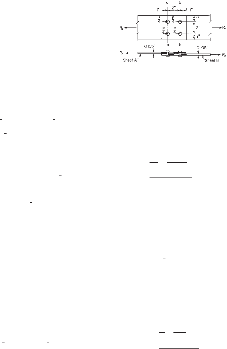
Example 8.5 Check the adequacy of the bearing-type
connection as shown in Fig. 8.31. Use four
1
2
-in.-diameter
A325 bolts and A606 Grade 50 steel sheets (F
y
= 50 ksi
and F
u
= 70 ksi). Assume that washers are used under the
bolt head and nut and that threads are not excluded from
shear planes. Use standard holes and the ASD method. The
deformation around bolt holes is not a design consideration.
SOLUTION
1. Shear, Spacing, and Edge Distance in Line of Stress.
Since the inside sheet is thicker than the sum of
the thickness of both outside sheets and the distance
from the center of the hole to the end of the plate
is the same for inside and outside sheets, the outside
sheets will govern the design. For F
u
/F
y
= 70/50 =
1.4 > 1.08, the safety factor to be used for determining
the allowable shear strength of the outside sheets is
2.0 according to Section 8.4.2.5.
Using Eq. (8.51), the allowable design shear
strength of the outside sheet can be computed as
follows:
P
a
=
P
n
=
teF
u
2.0
=
(0.105)(1)(70)
2.0
= 3.675 kips/bolt >
9
4
= 2.25 kips/bolt OK
In addition, the following requirements should also be
checked:
a. Distance from center of hole to edge of adjacent
hole:
2 −
1
2
(
1/2 + 1/16
)
= 1.72 in.
>(e = 1.0in.) OK
b. Distance between centers of bolt holes:
2in.>(3d = 1.5in.) OK
c. Distance from center of the hole to end of plate:
1in.>(1
1
2
d = 0.75 in.) OK
2. Tensile Strength of Steel Sheets
Based on Section C2 of the 2007 edition of the
specification, the allowable tensile strength of the
Figure 8.31 Example 8.5.
292 8 CONNECTIONS
outside sheet can be computed as follows:
(i) For yielding [Eq. (6.2)],
T
a
=
A
g
F
y
1.67
=
(4.0 ×0.105)(50)
1.67
= 12.57 kips > 9kips OK
(ii) For fracture away from the connection [Eq.
(6.3)],
T
a
=
A
n
F
u
2.00
As in Example 8.4, A
n
= 0.30 in.
2
,and
T
a
=
(0.30)(70)
2.00
= 10.5kips> 9kips OK
Based on Section 8.4.2.6, the allowable tensile
strength of the outside steel sheet for double shear
can be calculated from Eq. (8.52) with a safety
factor of 2.0:
P
a
=
P
n
=
A
n
F
t
2.0
F
t
= 70 ksi
P
a
=
(0.30)(70)
2.0
= 10.50 kips > 9kips OK
By inspection, it is not necessary to check the inside
sheet for tensile strength because it is thicker than
the sum of the thicknesses of both outside sheets.
3. Bearing Strength between Bolts and Steel Sheets. The
allowable bearing strength can be obtained using
Section 8.4.2.7 for the inside sheet and the outside
sheets which are used in a double-shear connection:
a. For the inside sheet, the allowable bearing strength
is
P
a
=
Cm
f
F
u
dt
=
(3.0)(1.33)(70)(0.5)(0.25)
2.50
= 13.96 kips/bolt >(
18
4
= 4.5 kips/bolt) OK
b. For the outside sheets, the allowable bearing
strength is
P
a
=
Cm
f
F
u
dt
=
(3)(1.0)(70)(0.5)(0.105)
2.50
= 4.41 kips/bolt <(
18
4
= 4.5 kips/bolt) NG
4. Shear Strength in Bolts. When threads are not
excluded from shear planes, the nominal shear stress
for A325 bolts can be obtained from Table 8.5
that is,
F
nv
= 54 ksi
The allowable shear strength for the double shear
condition is
P
a
=
(2)(A
b
F
nv
)
=
(2)(0.196)(54)
2.4
= 8.82 kips/bolts >(
18
4
= 4.5 kips/bolt) OK
On the basis of the above calculations for the ASD
method, it can be concluded that the given connection
is not adequate for the applied load of 18 kips. The
same design considerations should be used for the
LRFD method.
8.4.3 Additional Design Information on Bolted
Connections
The research work reviewed at the beginning of Section
8.4 dealt mainly with the previous studies conducted in the
United States. The design criteria discussed in Section 8.4.2
were based on the 2007 edition of the AISI North American
specification.
1.345
Additional research work on bolted connections has
been conducted by Baehre and Berggren,
1.25,8.4
Stark
and Toma,
8.5,8.49,8.50
Marsh,
8.51
LaBoube,
8.52
Zadanfar-
rokh and Bryan,
8.71
Carril, Holcomb, LaBoube, and
Yu,
6.23–6.25
Seleim and LaBoube,
8.72
Kulak and Wu,
8.73
Wheeler, Clarke, Hancock, and Murray,
8.74
Rogers and
Hancock,
2.55–2.61
and other researchers.
1.362–1.366
The
criteria for the bolted connections and the additional
information on mechanical fasteners have been published
in Refs. 8.4, 8.7, 8.8, and 8.53. See also other design
specifications mentioned in Chapter 1.
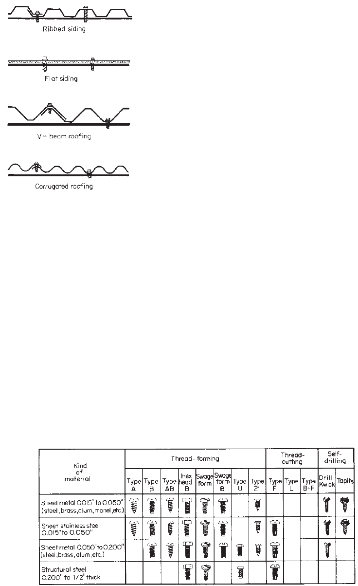
8.5 SCREW CONNECTIONS
Screws can provide a rapid and effective means to fasten
sheet metal siding and roofing to framing members and to
make joints in siding and roofing, as shown in Fig. 8.32.
They can also be used in steel framing systems and roof
trusses and to fasten gypsum sheathing to metal studs and
tracks.
Figure 8.33 shows some types of self-tapping screws
generally used in building construction.
8.2
Self-drilling
tapping screws are to be in compliance with ASTM
C1513.
8.109
Guidance for selection of screws can be found
in the publication of the Cold-Formed Steel Engineers
Institute.
8.110
8.5.1 AISI Design Criteria
The AISI design provisions for screw connections were
developed in 1993.
8.83
The background information on the
AISI design criteria is summarized by Pekoz in Ref. 8.54.
SCREW CONNECTIONS 293
Figure 8.32 Application of self-tapping screws.
8.1
Based on the ECCS Recommendations and the British Stan-
dard with the results of over 3500 tests from the United
States, Canada, Sweden, United Kingdom, and the Nether-
lands, the following requirements were developed as given
in Section E4 of the 1996 edition of the AISI Specification
for the design of screw connections and were essentially
unchanged in the 2007 edition of the Specification:
E4 Screw Connections
The following notation applies to this section of the Specifica-
tion:
d = nominal screw diameter
= 3.00 (ASD)
φ = 0.50 (LRFD)
= 0.40 (LSD)
P
ns
= nominal shear strength [resistance] per screw
P
ss
= nominal shear strength [resistance] of the screw
P
nt
= nominal tension strength [resistance] per screw
P
ts
= nominal shear strength [resistance] of the screw
P
not
= nominal pull-out strength [resistance] per screw
P
nov
= nominal pull-over strength [resistance] per screw
t
1
= thickness of member in contact with screw head or
washer (Figs. 8.35 and 8.36)
t
2
= thickness of member not in contact with screw head
or washer (Figs. 8.35 and 8.36)
F
u1
= tensile strength of member in contact with screw head
or washer
F
u2
= tensile strength of member not in contact with screw
head or washer
All E4 requirements shall apply to screws with 0.08 in. (2.03
mm) ≤ d ≤ 0.25 in. (6.35 mm). The screws shall be thread
forming or thread cutting, with or without a self-drilling point.
Alternatively, design values for a particular application shall
be permitted to be based on tests according to Chapter F. For
diaphragm applications, Section D5 shall be used.
Screws shall be installed and tightened in accordance with
the manufacturer’s recommendations.
The nominal screw connection strengths [resistances] shall
also be limited by Section C2.
E4.1 Minimum Spacing
The distance between the centers of fasteners shall not be less
than 3d .
E4.2 Minimum Edge and End Distance
The distance from the center of a fastener to the edge of
any part shall not be less than 1.5d. If the end distance is
parallel to the force on the fastener, the nominal shear strength
[resistance] per screw, P
ns
, shall be limited by Section E4.3.2.
E4.3 Shear
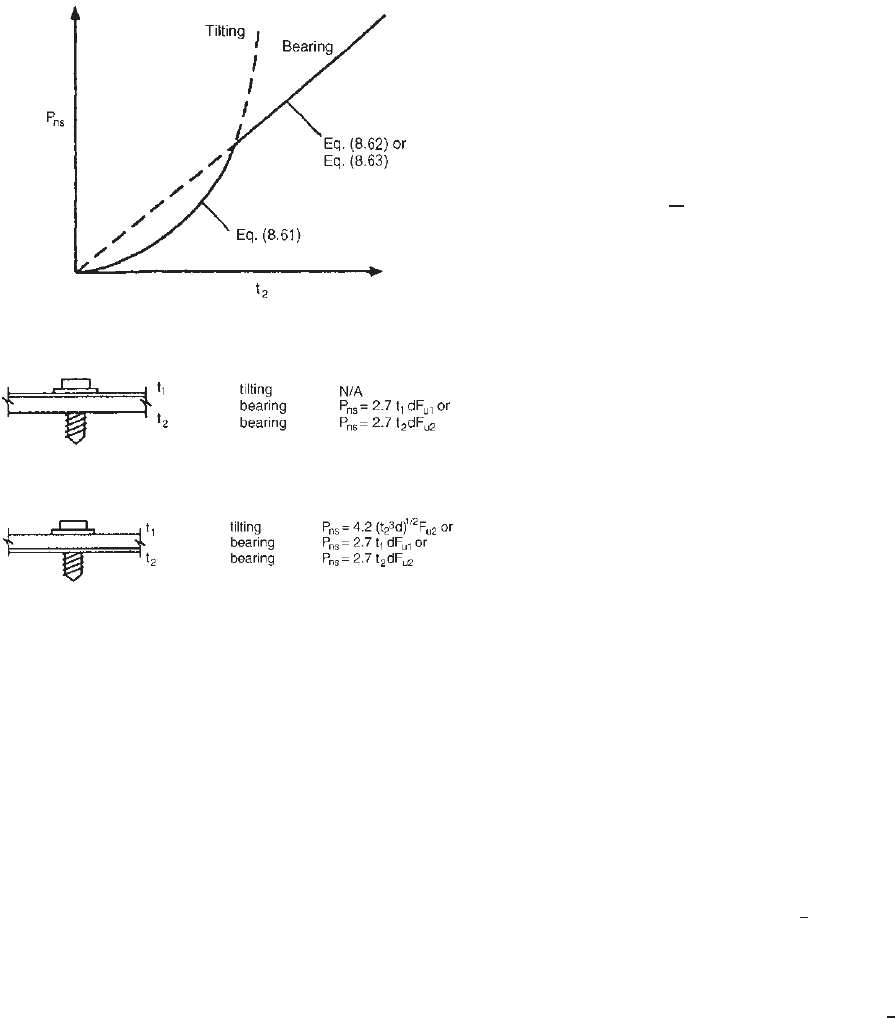
E4.3.1 Connection Shear Limited by Tilting and Bearing
The nominal shear strength [resistance] per screw, P
ns
,shall
be determined as follows: For t
2
/t
1
< 1.0, P
ns
shall be taken
Figure 8.33 Types of self-tapping screws.
8.3
(Courtesy of Parker-Kalon Corporation.)
294 8 CONNECTIONS
Figure 8.34 Comparison of tilting and bearing.
1.310,1.346
Figure 8.35 Design equations for t
2
/t
1
2.5.
Figure 8.36 Design equations for t
2
/t
1
1.0.
as the smallest of
P
ns
= 4.2(t
3
2
d)
1/2
F
u2
(8.61)
P
ns
= 2.7t
1
dF
u1
(8.62)
P
ns
= 2.7t
2
dF
u2
(8.63)
For t
2
/t
1
≥ 2.5, P
ns
shall be taken as the smaller of
P
ns
= 2.7t
1
dF
u1
[Eq. (8.62)]
P
ns
= 2.7t
2
dF
u2
[Eq. (8.63)]
For 1.0 <t
2
/t
1
< 2.5, P
ns
shall be determined by linear inter-
polation between the above two cases.
E4.3.2 Connection Shear Limited by End Distance
The nominal strength shear strength per screw, P
ns
, shall not
exceed
P
ns
= teF
u
(8.64)
where t = thickness of part in which the end distance is
measured
e = distance measured in line of force from center of
a standard hole to nearest end of connected part.
E4.3.3 Shear in Screws
The nominal strength [resistance] of the screw shall be P
ss
as
reported by the manufacturer or determined by independent
laboratory testing. In lieu of the value provided in Section E4,
the safety factor or resistance factor shall be permitted to be
determined in accordance with Section F1 and shall be taken
as 1.25 ≤ 3.0 (ASD), φ/1.25 ≥ 0.5 (LRFD),or φ/1.25 ≥ 0.4
(LSD).
E4.4 Tension
For screws which carry tension, the head of the screw or
washer, if a washer is provided, shall have a diameter d
h
or
d
w
not less than
5
16
in. (7.94 mm). Washers shall be at least
0.050 in. (1.27 mm) thick.
E4.4.1 Pull-Out
The nominal pull-out strength [resistance], P
not
, shall be calcu-
lated as follows:
P
not
= 0.85t
c
dF
u2
(8.65)
where t
c
is the lesser of the depth of the penetration and the
thickness, t
2
.
E4.4.2 Pull-Over
The nominal pull-over strength [resistance], P
nov
, shall be
calculated as follows:
P
nov
= 1.5t
t
d
w
F
u1
(8.66)
where d
w
is the pull-over diameter determined in accordance
with (a), (b), or (c) as follows:
(a) For a round head, a hex head (Fig. 8.37), or hex washer
head (Figure 8.37) screw with an independent and solid
steel washer beneath the screw head,
d
w
= d
h
+ 2t
w
+ t
1
≤ d
w
(8.67)
where d
h
= screw head diameter or hex washer head
integral washer diameter
t
w
= steel washer thickness
d
w
= steel washer diameter
(b) For a round head, a hex head, or a hex washer head screw
without an independent washer beneath the screw head:
d
w
= d
h
but not larger than
1
2
in. (12.7mm)
(c) For a domed (nonsolid and independent) washer beneath
the screw head (Fig. 8.37), it is permissible to use d
w
as
calculated in Eq. (8.67) with d
h
, t
w
,andt
1
,asdefinedin
Fig. 8.37. In the equation, d
w
cannot exceed
5
8
in. (16 mm).
Alternatively, pull-over design values for domed washers,
including the safety factor, , and the resistance factor, φ,
shall be permitted to be determined by test in accordance
with Chapter F.
E4.4.3 Tension in Screws
The nominal strength [resistance] of the screw shall be P
ss
as
reported by the manufacturer or determined by independent
laboratory testing. In lieu of the value provided in Section E4,