API RP 2T-2010 Planning, Designing, and Constructing Tension Leg Platforms
Подождите немного. Документ загружается.


PLANNING, DESIGNING, AND CONSTRUCTING TENSION LEG PLATFORMS 121
9.6.2 Tendon Pipe
9.6.2.1 General
The tendon pipe cross-section should be designed to safely resist the combined effect of global static loads
arising from pre-tension, tension and bending, which react to the environmental loads acting on the hull, and
external hydrostatic pressure. When local discontinuities are present in an otherwise straight and continuous
pipe body, local secondary bending stresses through the thickness of the pipe section are introduced and the
tendon pipe should also be designed to locally resist the resulting membrane and bending stresses.
The tendon pipe body is not as susceptible to cyclic loads as compared to pipe-to-pipe or pipe-to-connector
girth welds, provided that no damage is inflicted to inner or outer diameter pipe surfaces (ID or OD). One
means of protecting the OD is by using robust protecting coatings. Corrosion (pitting) on the ID should be
prevented during storage, fabrication, and service or allowed for in the design.
9.6.2.2 Pipe Acting Stresses
9.6.2.2.1 General
The global loads obtained according to the safety criteria defined in 5.2 should be used to generate global net
section stresses. If changes in diameter or wall thickness are present, then local through-thickness bending
stresses will also act on the pipe.
9.6.2.2.2 Global Net Section Stress
The net section stress at a cross-section results from axial load and general bending moments. The global
axial stress should be calculated as the normal stress acting on the gross cross-sectional area. Global
bending stress should be obtained as the extreme-fiber normal stress due to the bending moment acting on
the pipe cross section.
9.6.2.2.3 Local Stresses
Local stresses developed in tendons at diameter and thickness transitions should be quantified as described
in 9.6.2.2.4 and 9.6.2.2.5.
9.6.2.2.4 Diameter Transitions
Sectional transitions may be included in the pipe body where a reduction in the tendon diameter-to-thickness
ratio is required. However, the presence of sectional transitions in the tendon pipe body in conjunction will
result in local through-thickness bending stresses due to eccentricity of the global section load path, as well
as hoop stresses due to unbalanced radial loads at the junctions between the transition piece and the pipes.
The magnitude of these stresses depends on the transition piece configuration. Bell-shaped forgings, as
depicted in Figure 11, minimize the local additional stresses. Care should be taken to size the length of the
“straight sections” at the top and bottom such that the local stress levels have essentially returned to the
nominal pipe body stress at the locations where circumferential girth welds are to be made. Otherwise an
additional secondary local stress will be present at the weld, adversely affecting the fatigue life of the girth
weld.
The additional bending (f
b
') and hoop (f
h
') stresses may be calculated via finite element analysis (FEA) or
conservatively estimated according to Equation (36) and Equation (37), per API 2A-WSD, Section 3.4.
'
c
o
bab
2
0.6 ( )
()tan
ttt
D
fff
t
+
=+α
(36)
Copyright American Petroleum Institute
Provided by IHS under license with API
Licensee=Shell Global Solutions International B.V. Main/5924979112, User=Low, Ko
Not for Resale, 01/31/2011 00:10:44 MST
No reproduction or networking permitted without license from IHS
--``,`,```,,,``,`,``,,,,,,,,,,`-`-`,,`,,`,`,,`---

122 API RECOMMENDED PRACTICE 2T
'
hab
0.45 ( ) tan
o
t
D
fff
=+α
(37)
where
t is the tendon thickness;
t
c
is the cone thickness;
f
a
is the mean tensile stress, T/A
s
;
f
b
is the outer fiber bending stress, M D
o
/2I ;
α is one-half of the cone apex angle;
T is the tendon wall tension, T
e
− pA
o
;
T
e
is the tendon effective tension;
p is the hydrostatic pressure outside the tendon at bottom elevation (positive);
D
o
is the tendon outside diameter;
D
i
is the tendon inside diameter;
A
o
is the tendon outside cross-sectional area, π D
o
2
/ 4 ;
A
s
is the tendon steel cross-sectional area, π (D
o
2
− D
i
2
)/4 ;
I is the tendon steel moment of inertia, π (D
o
4
− D
i
4
)/64.
When (f
a
+ f
b
) is tensile, the hoop stress f
h
' is tensile at the smaller-diameter junction and compressive at the
larger-diameter junction.
Referring to Figure 11, the acting radial, longitudinal and hoop stresses to enter the design criteria should be
taken as:
r
h
z
b
ab
θ
h
h
σ
'
σ
'
σ
p
f
f
ff
f
f
==−
=++
=+
(38)
9.6.2.2.5 Thickness Transitions
Figure 12 depicts a typical thickness transition where local bending and membrane, or net section stress,
developed locally through thickness. For strength checks, these stresses should be obtained from
linearization, as detailed in C.5.1.
Copyright American Petroleum Institute
Provided by IHS under license with API
Licensee=Shell Global Solutions International B.V. Main/5924979112, User=Low, Ko
Not for Resale, 01/31/2011 00:10:44 MST
No reproduction or networking permitted without license from IHS
--``,`,```,,,``,`,``,,,,,,,,,,`-`-`,,`,,`,`,,`---
PLANNING, DESIGNING, AND CONSTRUCTING TENSION LEG PLATFORMS 123
Figure 11—Local Stress Check at Tendon Section Transitions
Copyright American Petroleum Institute
Provided by IHS under license with API
Licensee=Shell Global Solutions International B.V. Main/5924979112, User=Low, Ko
Not for Resale, 01/31/2011 00:10:44 MST
No reproduction or networking permitted without license from IHS
--``,`,```,,,``,`,``,,,,,,,,,,`-`-`,,`,,`,`,,`---
124 API RECOMMENDED PRACTICE 2T
Figure 12—Typical Section, Applied Loads, and Stress Distributions Through-thickness
9.6.2.3 Pipe Strength Criteria
9.6.2.3.1 General
The tendon pipe should be designed to meet both the global and local strength criteria set forth below.
The industry practice includes use of tension/collapse interaction equations developed for API 2A-LRFD,
D.3.3, but with either WSD or LRFD safety factors. See C.3 for additional information.
For designs using the working stress designs (WSD) and load and resistance factor design (LRFD)
approaches, the recommended criteria are described in 9.6.2.3.2 and 9.6.2.3.3 respectively.
9.6.2.3.2 Global Tension-collapse Strength Criteria with WSD Safety Factors
The tendon pipe subjected to longitudinal tensile stresses arising from the combined action of tension and
bending acting in conjunction with hydrostatic pressure should satisfy the following interaction equations.
22
0.6 1.0AB AB
η
++ ≤
(39)
tbt
y
()
f
fSF
A
F
+
=
(40)
hc
hc
f
SF
B
F
=
(41)
hc
y
54
F
F
=−
η
(42)
Differential
Stress
Average
Stress
Linear
Distribution
Peak stress
Elastic
Distribution
r
t
p
r
e
s
s
u
r
e
P
o
o
σ
σ
()r
1
σ
l
σ
(
)
r
p
r
e
s
s
u
r
e
Pi
id
Copyright American Petroleum Institute
Provided by IHS under license with API
Licensee=Shell Global Solutions International B.V. Main/5924979112, User=Low, Ko
Not for Resale, 01/31/2011 00:10:44 MST
No reproduction or networking permitted without license from IHS
--``,`,```,,,``,`,``,,,,,,,,,,`-`-`,,`,,`,`,,`---
PLANNING, DESIGNING, AND CONSTRUCTING TENSION LEG PLATFORMS 125
where
f
t
is the axial tensile stress due to wall tension;
f
b
is the outer fiber bending stress due to bending moment;
f
h
is the hoop stress due to hydrostatic pressure;
F
he
is the elastic hoop buckling stress;
F
hc
is the critical hoop buckling stress.
The elastic and critical hoop buckling stresses, F
he
and F
hc
respectively, are defined as follows:
F
he
= 0.88E (t/D)
2
(43)
where
D is the tendon pipe outer diameter;
t is the tendon pipe wall thickness;
E is the modulus of elasticity;
If F
he
< 0.55F
y
(elastic buckling),
F
hc
= F
he
(44)
If F
he
> 0.55F
y
(inelastic buckling),
0.4
he
hc y y
y
0.7
F
F
FF
F
⎡⎤
=≤
⎢⎥
⎢⎥
⎣⎦
(45)
The safety factors for tension, SF
t
, and for hydrostatic collapse, SF
c
, used in the interaction check are listed in
Table 8 (see C.3).
Table 8—Safety Factors for Tension-collapse Check
Safety Criteria
Tensile
SF
t
Hoop
SF
c
A (operating) 1.67 1.63
B (extreme) 1.25 1.38
S (survival) 1.05 1.25
Tendon pipe subjected to compressive wall stresses and hydrostatic pressure should use the appropriate
analysis methods and safety factors provided in API 2A-WSD or API 2A-LRFD.
Copyright American Petroleum Institute
Provided by IHS under license with API
Licensee=Shell Global Solutions International B.V. Main/5924979112, User=Low, Ko
Not for Resale, 01/31/2011 00:10:44 MST
No reproduction or networking permitted without license from IHS
--``,`,```,,,``,`,``,,,,,,,,,,`-`-`,,`,,`,`,,`---

126 API RECOMMENDED PRACTICE 2T
9.6.2.3.3 Global Tension-collapse Strength Criteria with Load and Resistance Factors
The tendon pipe subjected to longitudinal tensile stresses arising from the combined action of tension and
bending acting in conjunction with hydrostatic pressure should satisfy the following interaction equation, which
is repeated from Equation (39):
22
0.6 1.0AB AB
η
++ ≤
(46)
In the LRFD approach, the terms are defined as:
tb
ty
()
f
f
A
F
+
=
φ
(47)
h
hhc
f
B
F
=
φ
(48)
hc
y
54
F
F
η= −
(49)
where, in the LRFD approach
f
t
is the axial tensile stress due to the factored wall tension;
f
b
is the outer fiber bending stress due to the factored bending moment;
f
h
is the hoop stress due to the factored hydrostatic pressure;
F
he
is the elastic hoop buckling stress;
F
hc
is the critical hoop buckling stress.
The elastic and critical hoop buckling stresses, F
he
and F
hc
respectively, are defined as follows:
F
he
= 0.88E(t/D)
2
(50)
where
E is the modulus of elasticity;
t is the thickness of the unstiffened tendon pipe;
D is the thickness of the unstiffened tendon pipe.
If F
he
< 0.55 F
y
(elastic buckling) F
hc
= F
he
(51)
If F
he
> 0.55F
y
(inelastic buckling)
0.4
he
hc Y Y
y
0.7
F
F
FF
F
⎡⎤
=≤
⎢⎥
⎢⎥
⎣⎦
(52)
Copyright American Petroleum Institute
Provided by IHS under license with API
Licensee=Shell Global Solutions International B.V. Main/5924979112, User=Low, Ko
Not for Resale, 01/31/2011 00:10:44 MST
No reproduction or networking permitted without license from IHS
--``,`,```,,,``,`,``,,,,,,,,,,`-`-`,,`,,`,`,,`---
PLANNING, DESIGNING, AND CONSTRUCTING TENSION LEG PLATFORMS 127
The load factors for TLP tension response are defined relative to static loads (pretension and hydrostatic
pressure), environmental tension effects, and tension margins. The load factors L
1
, L
2
and L
3
and resistance
factors
φ
t
and φ
h
used in the interaction code check are listed in Table 9.
Table 9—Load and Resistance Factors for Tension-collapse Check
Design
Condition
Load Factors Resistance Factors
L
1
L
2
L
3
φ
t
φ
h
Operating 1.00 1.30 1.50 0.95 0.8
Extreme 1.00 1.10 1.35 0.95 0.8
Survival 1.00 1.00 1.00 0.95 0.8
where
L
1
is the load factor for the design margin;
L
2
is the load factor for the static pretension;
L
3
is the load factor for the environmental and inertia loads;
φ
t
is the resistance factor for the axial, bending and shear strength;
φ
h
is the resistance factor for the hoop buckling strength.
In the analysis, the inertia loads are not factored separately from environmental loads because tendon tension
responses are part of an overall dynamic system response, which includes both environmental and inertial
components. It is not feasible to separate applied environmental loads from dynamic inertia loads in a general
response model.
The level of uncertainty of inertia loads is considered similar to that of applied environmental loads in TLP
analysis.
The factored loads are defined in Equation (53) through Equation (55).
The factored wall tension is defined as:
(53)
where
T
margin
is the total of tension margins added external to the response simulation;
T
pre
is the pretension;
T
tide
is the tendon tension increase due to the tide and storm surge;
T
mean
is the mean tension due to the mean environmental loads (including setdown effects);
T
dyn
is the dynamic tension response induced by the environmental, including the inertia portion of
the response.
The factored bending moment is defined as:
3 mean dyn
()MLM M=+
(54)
Copyright American Petroleum Institute
Provided by IHS under license with API
Licensee=Shell Global Solutions International B.V. Main/5924979112, User=Low, Ko
Not for Resale, 01/31/2011 00:10:44 MST
No reproduction or networking permitted without license from IHS
--``,`,```,,,``,`,``,,,,,,,,,,`-`-`,,`,,`,`,,`---

128 API RECOMMENDED PRACTICE 2T
where
M
mean
is the mean bending moment;
M
dyn
is the dynamic bending moment.
The factored hydrostatic pressure is defined as:
2w z
P
LH=γ
(55)
where
w
γ
is the density of seawater;
H
z
is the submerged depth of the tendon section.
In the LRFD factor approach, tendon pipe net section stress utilization ratio shall be checked separately using
Equation (39). The A ratio in the equation shall be no greater than 1.0 based on the factors of safety defined
in Table 8.
9.6.2.3.4 Local Stresses
Local stresses developed due to diameter or thickness transition in the tendon should be checked according
to the following criteria.
a) Diameter transitions—When the hoop stress f
h
' is tensile, a local check based on a von Mises equivalent
stress at the outer fiber should be made according to the following stress criteria:
y
22
2
12
r θθz
zr
mem+bend
707[ ]
σσ σσ
σσ
/
e
.((
() ) )
σ
SF
σ
=++≤
−−−
(56)
σ
y
is the nominal strength of the material and SF is the safety factor given in the Table 10 according to the
safety criteria.
When the hoop stress f
h
' is compressive, f
h
' should meet the criteria for F
hc
given in 9.6.2.3.2 or 9.6.2.3.3,
except that, in Equation (40) and Equation (47), (f
t
+ f
b
) becomes (f
t
+ f
b
+ f
h
′), and in Equation (41) and
Equation (48), f
h
becomes (f
h
+ f
h
′).
b) Thickness transitions—The radial and hoop components of stress approach zero such that the von Mises
equation reduces to the following checks for local membrane or net section stress
(σ
mem
) and combined
membrane plus bending stress (σ
mem+bend
).
y
mem
mem
SF
σ
σ≤
(57)
y
mem+bend
mem+bend
SF
σ
σ≤
(58)
The safety factors for local pipe strength may be taken according to Table 10.
Copyright American Petroleum Institute
Provided by IHS under license with API
Licensee=Shell Global Solutions International B.V. Main/5924979112, User=Low, Ko
Not for Resale, 01/31/2011 00:10:44 MST
No reproduction or networking permitted without license from IHS
--``,`,```,,,``,`,``,,,,,,,,,,`-`-`,,`,,`,`,,`---

PLANNING, DESIGNING, AND CONSTRUCTING TENSION LEG PLATFORMS 129
Table 10—Local Pipe Strength Safety Factors
Safety Criteria
Safety Factors
Membrane
Membrane +
Local Bending
A (operating) 1.67 1.11
B (extreme) 1.25 0.83
S (survival) 1.05 0.83
9.6.3 Tendon Girth Welds
Satisfying the strength criteria stipulated in 9.6.2 for the tendon pipe body ensures the strength performance
of the girth weld as long as the welds are overmatched in strength relative to the actual maximum pipe
material properties. Loss of pipe wall thickness resulting from dressing the weld reinforcements should be
considered in the design for local fatigue. Girth welds, however, are especially susceptible to cycling loads
due to the presence of flaws inherent to the welding process.
9.6.3.1 Girth Weld Acting Stresses
The cyclic loading acting on the welds to be considered here are the same as those acting on the pipe body
generated via the load analysis methods discussed in 9.4. Additionally, secondary local stress at the weld
resulting from the attachment of mechanical connectors, section transitions, pipe misalignment, or local thin
spots resulting from dressing of the weld reinforcement should be considered.
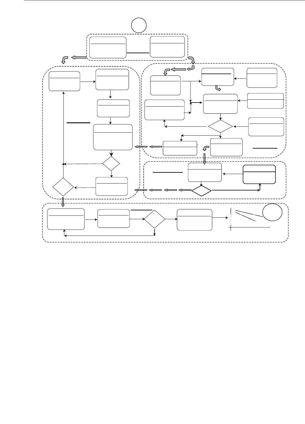
9.6.3.2 Girth Weld Fatigue Design
9.6.3.2.1 General
The reliable fatigue design of the tendon girth welds requires the interaction between analysis, fabrication
considerations, and qualification and/or confirmation testing as needed. Figure 13 shows an example of
elements to be considered in the fatigue design process for fracture-critical tendon girth welds, which is
complementary to that described in 9.2.5 for the overall design process.
9.6.3.2.2 Girth Weld Fatigue Damage Analysis
Based on the stress histories acting on the tendon girth welds, conventional Miner’s rule cumulative fatigue
damage should be conducted. The resistance side of the damage calculation should use a design S-N curve
consistent with the type and quality of weld sought.
Copyright American Petroleum Institute
Provided by IHS under license with API
Licensee=Shell Global Solutions International B.V. Main/5924979112, User=Low, Ko
Not for Resale, 01/31/2011 00:10:44 MST
No reproduction or networking permitted without license from IHS
--``,`,```,,,``,`,``,,,,,,,,,,`-`-`,,`,,`,`,,`---
130 API RECOMMENDED PRACTICE 2T
Figure 13—Design, Fabrication, and Verification Process for Fracture-critical Tendon Welds
For tendon welds designed not to be inspected for fatigue cracks in-service, the calculated S-N fatigue life
should be at least 10 times the planned life of the facility. A lower life design factor may be used when:
a) a proven, reliable in-situ inspection/crack detection method and an expedient replacement or repair plan
are to be employed, or
b) the uncertainties of the variables entering the damage calculations are reduced (Wirsching, 1986
[250]
). In
no case, however, should the fatigue life of the weld be less than three times the planned life of the
facility.
S-N design curves given by BS 7608, Table 7, for circumferential butt welds in tubes are recommended in
accordance with the manufacturing requirements, special inspection requirements and notes stipulated.
Welds made from one side but which otherwise meet all other requirements stipulated for Class C can also be
assessed with the Class C curve. Any other pertinent curve may be used, provided it is relevantly justified on
the basis of pertinent data. Invoking an endurance limit or change in slope, such as in BS 7608, should be
based on data that includes variable amplitude loading effects. If welds are ground properly (see 9.6.3.3) a
correction for thickness effect on fatigue may be waived. A thickness effect may also be waived if the S-N is
based on actual component size data (see C.4.1).
Require
-Tolerances
-Properties
Select
-Pipe Size
-Pipe Type
Analyze
Dynamic
Response
OK ?
Data
da/dN
Calculate
FM for Life
& Fracture
Yes
Assume
Flaw Size,
Local & Type
Require
-Life
-Max. Load
No
Select
Mech. Prop.
Set
Flaw Size
& type
Fatigue
Damage
Calculate Input
- SN Curve*
- SCF
Select
Inspection
Method
Determine
PoD and
Accuracy
Yes
No
OK ?
Make
Weld
Samples
Qualify
-Mech. Prop.
-Residual σ
-Hardness
Develop
Welding
Procedure
Inspect
Qualified
Samples
OK?
No
OK?
Yes
No
Material
Material
Welding
Welding
LIFE
LIFE
Select
Welding
Variables
Select
Yes
Analysis
Analysis
Inspection
Inspection
Start
Test
Fatigue &
Environment
Fatigue
Specimens
Design & Fab
S
N
tests
design
End
Inspect
Qualified
Samples
OK?
No
Testing
Testing
*
Copyright American Petroleum Institute
Provided by IHS under license with API
Licensee=Shell Global Solutions International B.V. Main/5924979112, User=Low, Ko
Not for Resale, 01/31/2011 00:10:44 MST
No reproduction or networking permitted without license from IHS
--``,`,```,,,``,`,``,,,,,,,,,,`-`-`,,`,,`,`,,`---