Baker R.C. Flow Measurement Handbook: Industrial Designs, Operating Principles, Performance, and Applications
Подождите немного. Документ загружается.

5.B DEFLECTION OF ORIFICE PLATE AT HIGH PRESSURE
107
TEFLON SEAL (SEAL
No
3)
HETALSEAL (SEALNo
1)
DIRECTION
OF
FLOW
OIRECTION
OF
FLOW
DIRECTION
FLOW
CTRINGS
METAL
SEAL (SEAL No
2)
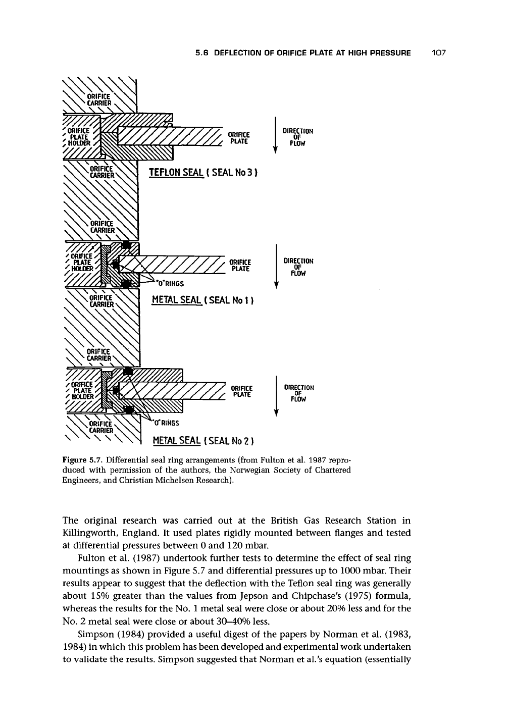
Figure 5.7. Differential seal ring arrangements (from Fulton et al. 1987 repro-
duced with permission of the authors, the Norwegian Society of Chartered
Engineers, and Christian Michelsen Research).
The original research was carried out at the British Gas Research Station in
Killingworth, England. It used plates rigidly mounted between flanges and tested
at differential pressures between 0 and 120 mbar.
Fulton et al. (1987) undertook further tests to determine the effect of seal ring
mountings as shown in Figure 5.7 and differential pressures up to 1000 mbar. Their
results appear to suggest that the deflection with the Teflon seal ring was generally
about 15% greater than the values from Jepson and Chipchase's (1975) formula,
whereas the results for the No. 1 metal seal were close or about 20% less and for the
No.
2 metal seal were close or about 30-40% less.
Simpson (1984) provided a useful digest of the papers by Norman et al.
(1983,
1984) in which this problem has been developed and experimental work undertaken
to validate the results. Simpson suggested that Norman et al.'s equation (essentially
108
ORIFICE PLATE METERS
that in
BS
1042: Sect. 1.5: 1997)
\
— Ci I
/
(5.13)
where
q
m
=
mass flow rate
Ap
=
differential pressure across the plate
E*
=
elastic modulus of plate material
D = orifice plate support diameter
h
=
thickness of orifice plate (=E in Figure 5.3, following ISO 5167)
could have simpler expressions for a\ and
C\
than given by Norman et al. because
the plate thickness will usually be fixed by the next most appropriate thickness of
material. Simpson, therefore, gave (as in the standard)
fli =0(0.135-0.1550)
d = 1.17-1.O60
13
To avoid plastic deformation, the differential pressure must be below
h
6(0.454-0.4340)
(5.14)
where
Metering
error
Slope
0.2
0.1
or
y
= yield stress for plate material
0 = orifice plate diameter ratio d/D
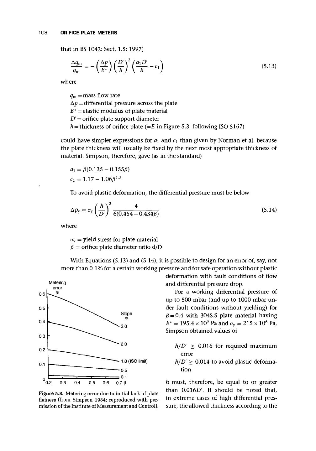
With Equations (5.13) and (5.14), it is possible to design for an error of, say, not
more than
0.1%
for a certain working pressure and for safe operation without plastic
deformation with fault conditions of flow
and differential pressure drop.
For a working differential pressure of
up to 500 mbar (and up to 1000 mbar un-
der fault conditions without yielding) for
0 = 0.4 with 304S.S plate material having
E*
= 195.4 x 10
9
Pa and a
y
= 215 x 10
6
Pa,
Simpson obtained values of
h/U > 0.016 for required maximum
error
h/D' > 0.014 to avoid plastic deforma-
tion
h must, therefore, be equal to or greater
than 0.016D'. It should be noted that,
in extreme cases of high differential pres-
sure,
the allowed thickness according to the
Figure 5.8. Metering error due to initial lack of plate
flatness (from Simpson 1984; reproduced with per-
mission of the Institute of Measurement and Control).
5.7 EFFECT OF PULSATION 109
standards may be exceeded in meeting these plate bending requirements. The stan-
dard also implies that a safety factor on a
Y
(of three) is a wise precaution.
Figure 5.8 gives curves for errors due to flatness slope against p ratio.
5.7 EFFECT OF PULSATION
In considering the installation of a flowmeter, the assumption is usually made that
the flow is steady. In many cases, this is probably a fair assumption. However, there
are situations when it is not the case (e.g., when a reciprocating compressor, an
internal combustion engine, or some form of rotary valve is in the line). It is often
very difficult to decide whether the flow is indeed steady or pulsating in some way.
We might idealize the pulsating flow as consisting of a sinusoidal ripple super-
imposed on a steady flow. This idealization is probably seldom valid, and little will
actually be known about the amplitude, frequency, or flow profile. Mottram (1992,
cf. BS 1042 Section 1.6, which uses some of his work), after the wise comment, "If
you can't measure it, damp it!" made some additional useful points.
• If the frequency is above about 2 Hz, differential pressure transducers will, gen-
erally, be too heavily damped to pick it up. (Transducers with a response up to 2
kHz or more are likely to be specified and to be more expensive.)
• The standard describes some detection techniques including the use of a thermal
probe to sense the presence of pulsation.
• Some flowmeter signals show indication of pulsation.
• In some cases, the error may be deduced from the raw flowmeter signal.
• Connecting leads in differential pressure meters can cause resonance and con-
fusing effects.
The orifice plate meter is affected by pulsation, and so it is necessary to reduce
the pulsation and to have an idea of the error likely from any residual pulsation.
The effects of pulsation on an orifice meter are:
a. Nonlinear
(square root)
error.
If a signal is averaged to obtain a mean flow, it is
necessary that the instantaneous flow be proportional to the signal. If this is not
so,
an error will be introduced.
b.
Inertia
error.
If the fluid does not follow the changes in the flow rate instanta-
neously, an error due to the inertia of the fluid will result.
c.
Velocity profile
effect This effect is a result of the change in profile from fully
developed to the unsteady flow.
d.
Resonance.
Resonance occurs because some component of the system is resonat-
ing at the pulsation frequency.
e. Limitations in the
pressure measurement
device.
If the pressure measurement device
does not respond correctly to pulsating flow, the pressure measurement may be
incorrect.
Of these, the most important are (a), (d), and (e), the last two of which are
related. The latter two are particularly possible in the connecting tubes between the
110 ORIFICE PLATE METERS
flow tube and the transducer, and because of the rate of response of the transducer.
A manometer will possibly be of little value in an application with pulsation.
Thus for (a), Gajan et al. (1992) reviewed work that showed that, for quite high
values of the ratio of rms fluctuating pressure difference to steady pressure difference,
up to 0.5 at least, the main error is due to the square root effect and can be eliminated
with a high speed response transducer. Even with a slow response transducer, the
error for the ratio, if within
0.1,
may be within about 1%.
Botros et al. (1992) looked at (d) and (e) and found that the combination of lines
and transmitter form a resonator that can amplify or attenuate. They recommended
that very short lines of essentially constant diameter and a transmitter with a small
volume and a high frequency response should be used.
Commercially available differential pressure transmitters are generally unsuit-
able for dynamic measurement (Clark 1992). The dynamic response of differen-
tial pressure transducer systems is significantly affected by length of transmission
line and whether the measurement medium is liquid or gas. Gas and liquid lines
appear to be susceptible to oscillations, and in liquid systems there is a need for
proper gas venting arrangements. Considerable care is required in order to make
reliable dynamic measurements particularly when using a liquid medium (Clark
1992).
The square root problem is shown by
\ f
JKpdt<
I- f
Apdt
(5.15)
t Jo
V
t Jo
A transducer with pressure connections that is capable of responding within a time
that is short compared with the period of the fluctuation, and the signal of which
is square-rooted immediately and then averaged, will give the correct average value.
This is essentially the left-hand side of the inequality (5.15). On the other hand,
if the pressure is averaged and then the square root is taken, this is essentially the
right-hand side of the inequality and the apparent flow rate will be high compared
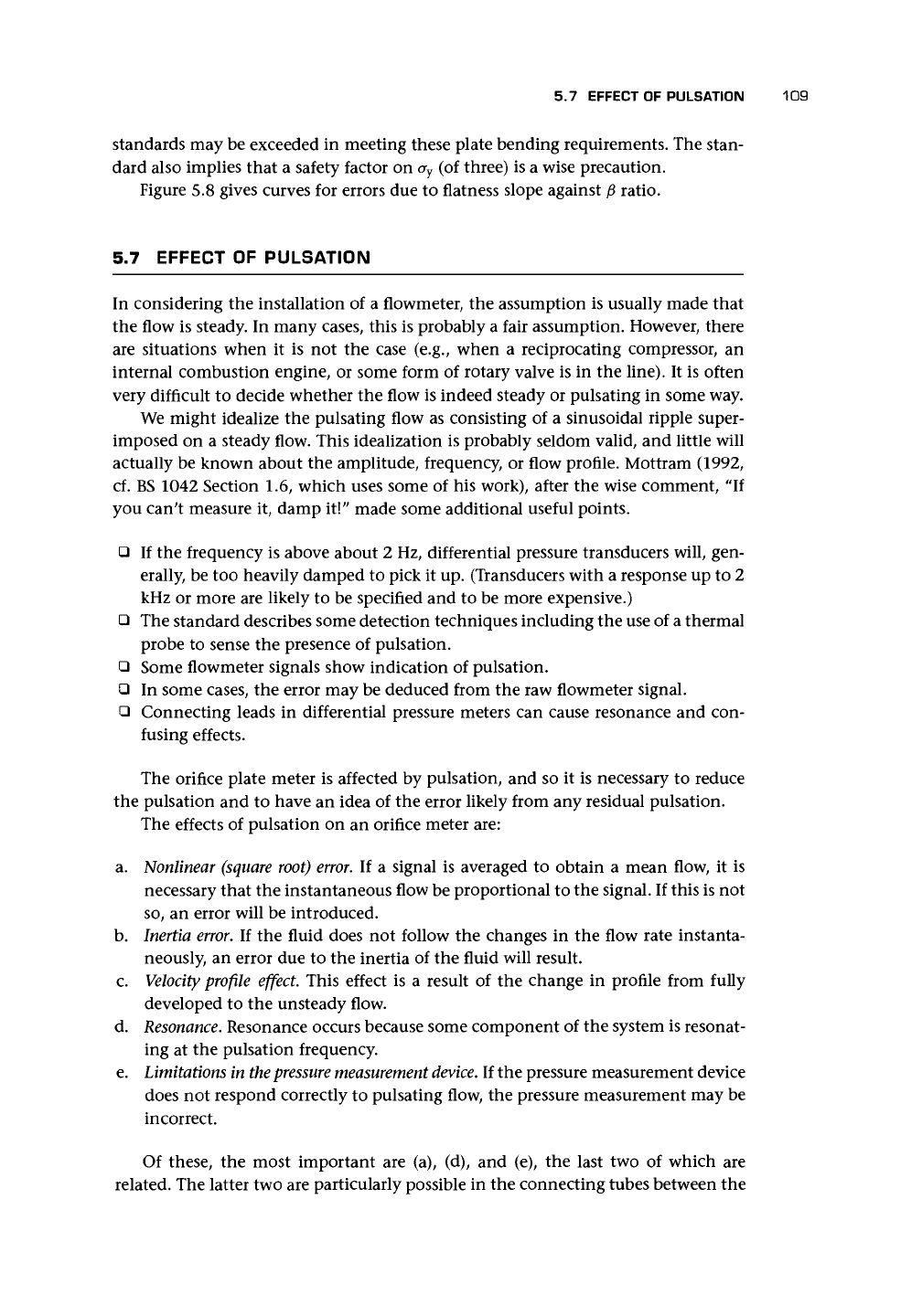
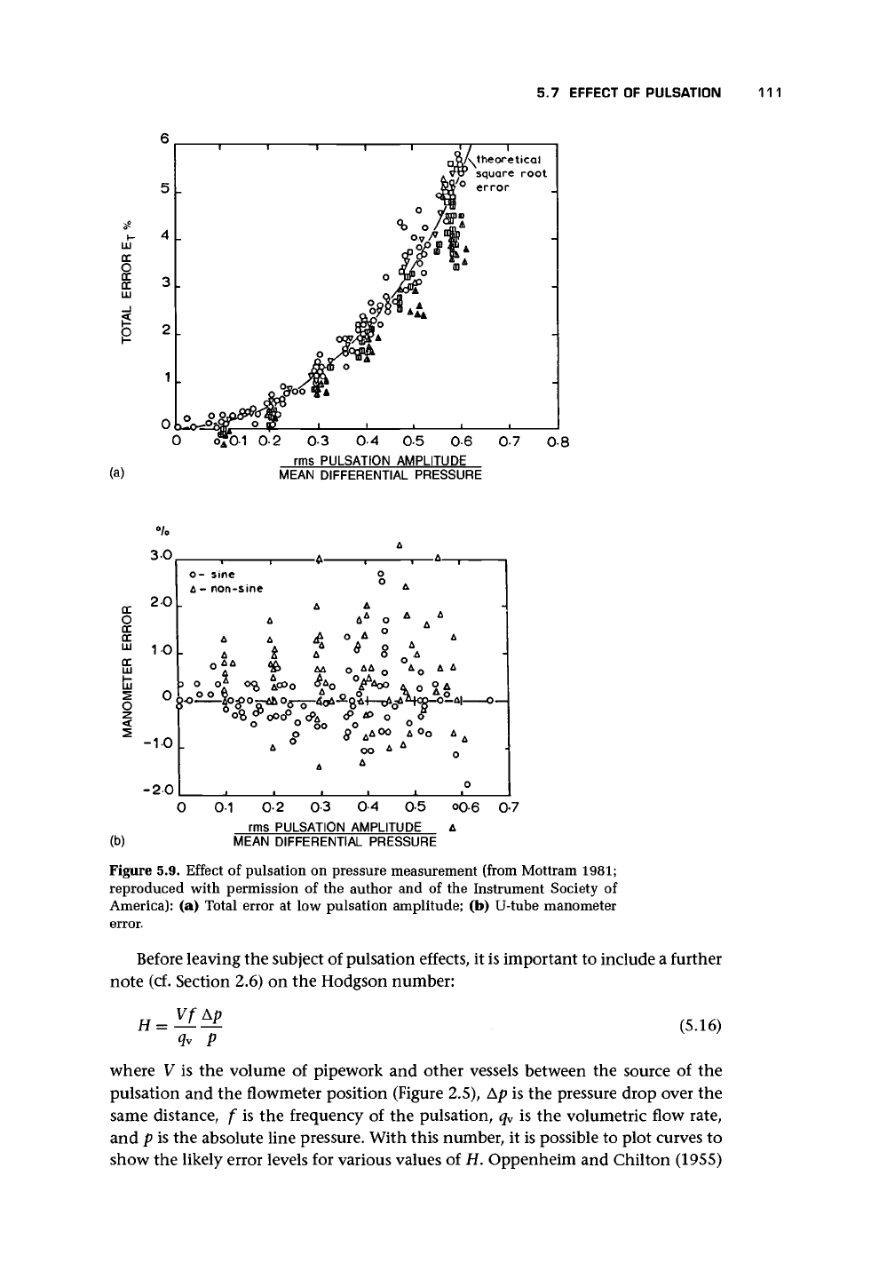
to the actual flow rate. Mottram's (1981) results for pulsation error are shown in
Figure 5.9(a), and they suggest that the experimental results confirm the dominance
of the square root error when compared with errors (b) and (c). However, Mainardi
et al. (1977) appeared to suggest that (b) and (c) cause a change in the coefficient so
that the effect of pulsation for a fluctuating ripple of 6% of the mean flow will cause
an error if pulsation is measured with a high frequency response transducer of 1.5%,
whereas the error is 4% for a 15% ripple. (Frequencies appeared to be up to about
50 Hz.)
Williams (1970) identified the possible sources of error when manometric devices
are used to indicate mean differential pressure in a pulsating flow as
• wave action and resonance effects in the connecting leads,
• volumes of ducts of varying section within the manometer and leads, and
• restrictions in the leads, which cause a nonlinear relationship between flow and
pressure drop and result in nonlinear damping.
The effect of pulsation on a manometer is shown in Figure 5.9(b).
5.7 EFFECT OF PULSATION
111
LLJ
DC
s
DC
LLJ
'\theoretical
square root
(a)
03 04 05 0-6
rms PULSATION AMPLITUDE
MEAN DIFFERENTIAL PRESSURE
07 08
DC
2
DC
LLJ
DC
LLJ
(b)
30
20
10
0
-1-0
-20
o- sine
A
- non-sine
A
o
A A
)
O O^ OQ
OO
6v
o
A
A
to
A
ooo°
A
A
A
A
A
5>A
OO
A
A
A
A
O A
°T
oo
A
A
0
° A
0
^ A
0
§ \
0
A
O
kjO
A
O
° o°
OO A O^
A
A
A
A A
O A
_O°_A|
O—
o
O
0-1
0-2 0-3 0-4
0-5 O0-6 0-7
rms PULSATION AMPLITUDE A
MEAN DIFFERENTIAL PRESSURE
Figure 5.9. Effect of pulsation on pressure measurement (from Mottram 1981;
reproduced with permission of the author and of the Instrument Society of
America): (a) Total error at low pulsation amplitude; (b) U-tube manometer
error.
Before leaving the subject of pulsation effects, it is important to include a further
note (cf. Section 2.6) on the Hodgson number:
(5.16)
q
y
p
where V is the volume of pipework and other vessels between the source of the
pulsation and the flowmeter position (Figure 2.5), Ap is the pressure drop over the
same distance, f is the frequency of the pulsation, q
v
is the volumetric flow rate,
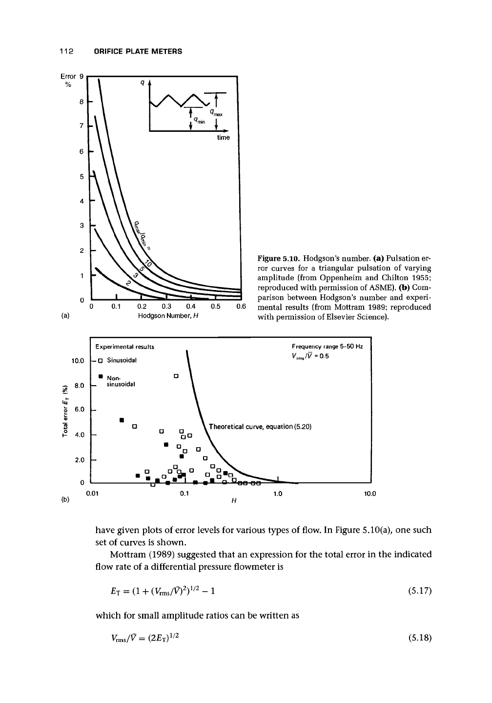
and p is the absolute line pressure. With this number, it is possible to plot curves to
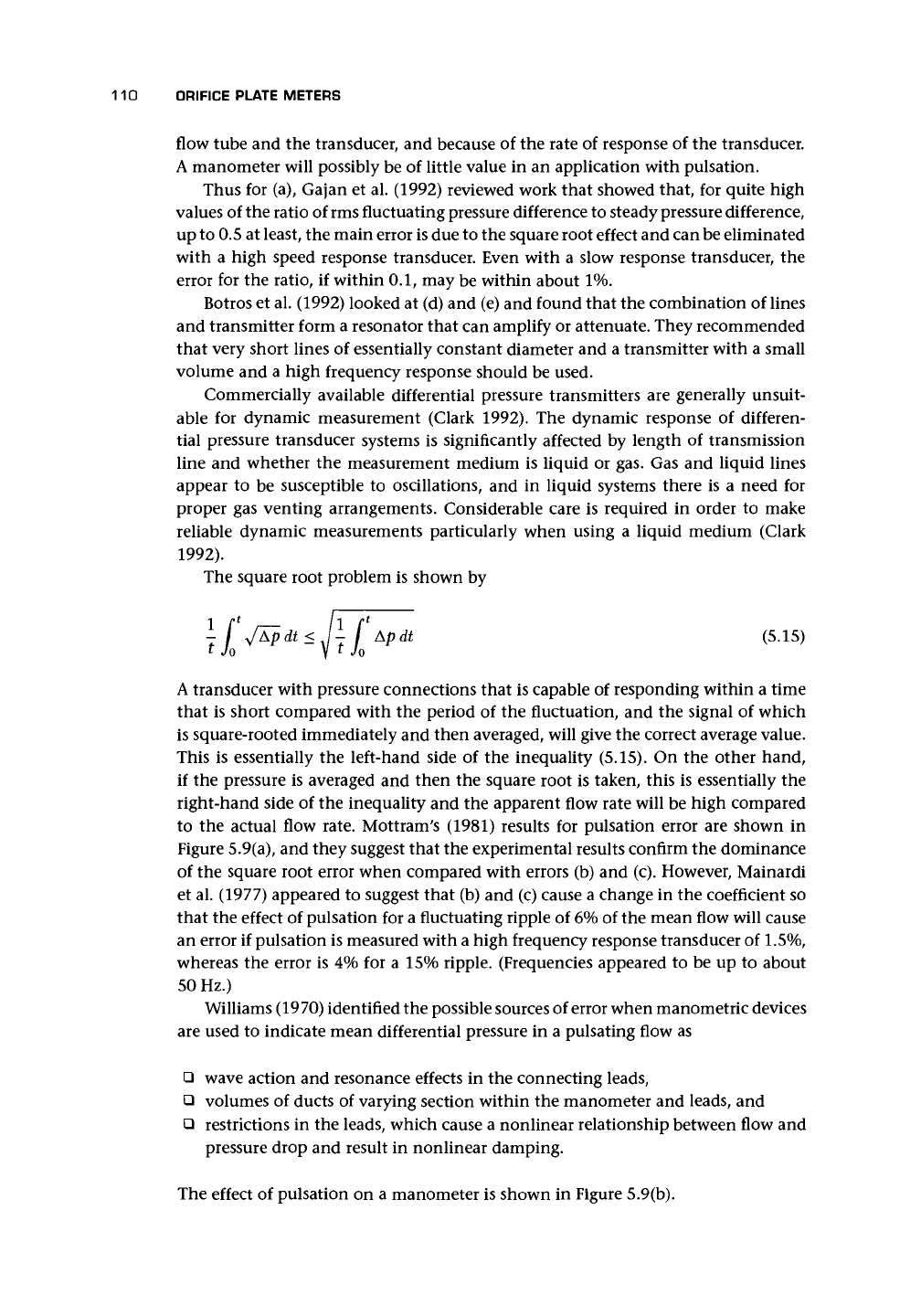
show the likely error levels for various values of H. Oppenheim and Chilton (1955)
112 ORIFICE PLATE METERS
0.2 0.3 0.4
Hodgson Number, H
Figure 5.10. Hodgson's number, (a) Pulsation er-
ror curves for a triangular pulsation of varying
amplitude (from Oppenheim and Chilton 1955;
reproduced with permission of
ASME).
(b) Com-
parison between Hodgson's number and experi-
mental results (from Mottram 1989; reproduced
with permission of Elsevier Science).
10.0
g
8
°
H
Uj
6.0 -
4.0 -
2.0 -
Experimental results
-O Sinusoidal
• Non-
_ sinusoidal
•
D
Q
•
- D <
2r#-HI
|
\
a
]
o
°a
Frequency r«
V IV -
O.E
i
\ Theoretical curve, equation (5.20)
\
a \
° V
•
^•
O
B°ao^5
^—.
jnge 5-50 Hz
>
(b)
0.01 0.1
1.0 10.0
have given plots of error levels for various types of flow. In Figure 5.10(a), one such
set of curves is shown.
Mottram (1989) suggested that an expression for the total error in the indicated
flow rate of a differential pressure flowmeter is
which for small amplitude ratios can be written as
V
vms
/V
= V
2
(5.17)
(5.18)
5.8 EFFECTS OF MORE THAN ONE FLOW COMPONENT 113
where V is the mean velocity and
V
rms
is the rms value of the unsteady velocity fluc-
tuation in the pipe. He then suggested that if
a
maximum allowable percentage error
is 0 where
</>
= 100£
T
, and using the criterion for damping in Equation (2.14), then
H 1 (WtQud
(
,
19
,
where subscript ud implies undamped and y is the isentropic index for the gas or
H (Wfod
(5<20)
y ~ V0
where K = 10/(4\/27r) = 0.563. He claimed that experimental evidence is available
to validate the safety of this criterion provided the flow pulsation amplitude can
be measured. Some of Mottram's (1989) data compared with Equation (5.20) with
K =0.563 is shown in Figure 5.10(b). Where estimation is necessary, he suggests a
safety margin by using K =
1.
This appears to be confirmed by the data that Mottram
(1989) included in his paper (cf. Sparks et al. 1989 who emphasized the problems
and the only safe solution - the removal of pulsation).
5.8 EFFECTS OF MORE THAN ONE FLOW COMPONENT
Attempts have been made to relate the differential flowmeter equation to the data for
flow of a fluid mixture, most commonly steam, through the orifice. The attempted
adjustments have followed three approaches:
1. Adjusting the value of density to reflect the presence of a second component (cf.
James 1965-6);
2.
Adjusting the discharge coefficient to introduce a blockage factor for the other
components, expressed as a function of the dryness (cf. Smith and Leang 1975);
3.
Relating the two-phase pressure drop to that which would have occurred if all
the flow were passing either
as
a gas or
as
a liquid. The ratio of two-phase pressure
drop to liquid flow pressure drop <I>j?
o
is equated to a function of x, the dryness
fraction.
Miller (1996) favored the third approach as being the easiest to use. It has also
been investigated by several workers, and various expressions for
<&j
o
have been
tabulated by Grattan et al. (1981) from the work of Chisholm (1977), Collins and
Gacesa (1970), James (1965-1966), and Watson et al. (1967). For other references,
the reader is referred to Baker (1991a).
The main reservation concerning some of these correlations relates to whether or
not they can be applied to different pipe geometries, fluids, Reynolds numbers, etc.
Steam
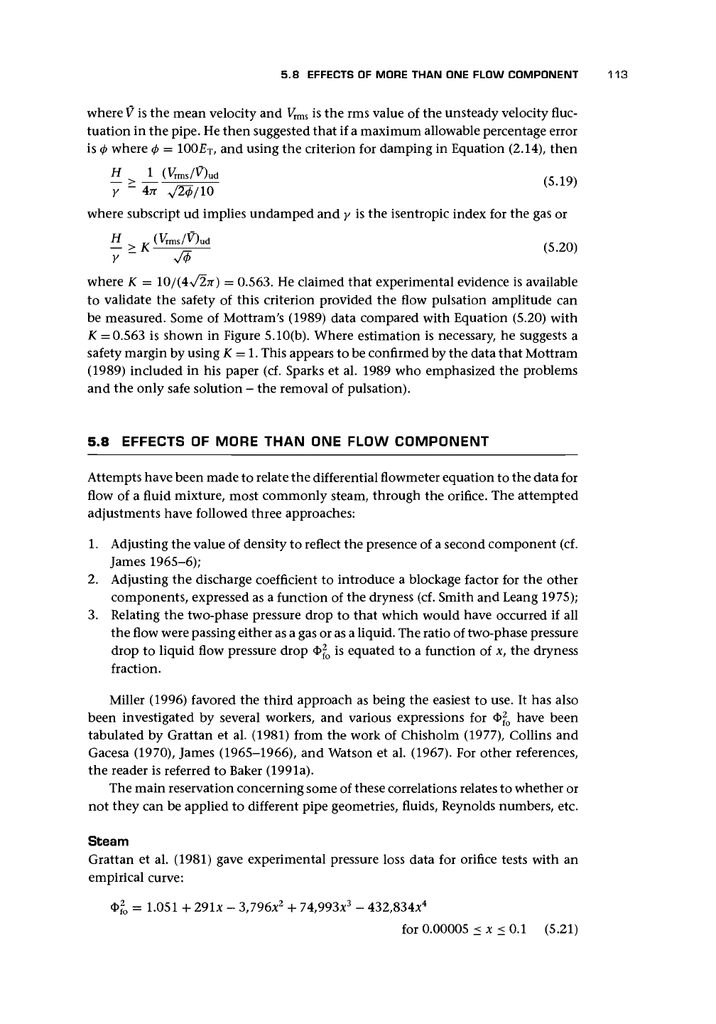
Grattan et al. (1981) gave experimental pressure loss data for orifice tests with an
empirical curve:
<$>l
= 1.051 +
291*
- 3,796x
2
+ 74,993x
3
- 432,834x
4
for 0.00005 < x < 0.1 (5.21)
114 ORIFICE PLATE METERS
100
i
0.0000!
0.0001
0.001
Mass dryness fraction x
.
0.01
Figure
5.11.
Experimental pressure loss data for orifice tests (from Grattan et
al.
1981;
reproduced
by permission of
NEL).
and this is shown in Figure 5.11. The scatter is an indication of the limited value of
such an empirical curve and of attempts to predict flowmeter performance in two-
phase flows. Rooney (1973) also obtained values for the parameter
4>^
o
(cf. Chisholm,
1967;
Chisholm and Leishman, 1969; Chisholm and Watson, 1966).
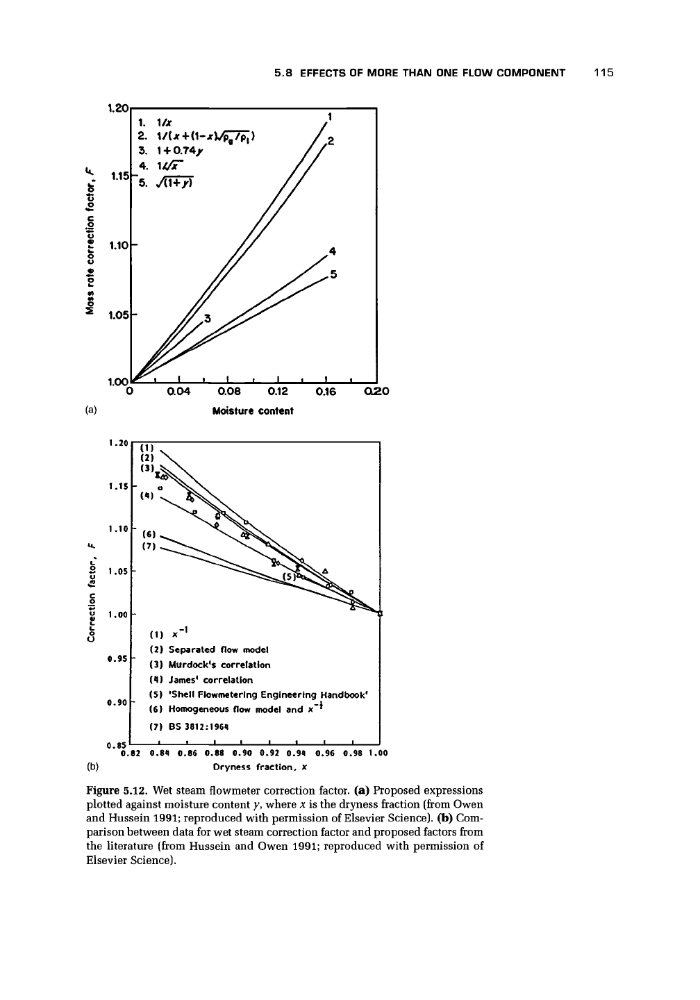
Owen and Hussein (1991) pointed out that if the water content was very small,
the droplets would probably have a negligible effect on the flowmeter response,
and so the mass flow should be corrected to allow for the mixture density rather
than the vapor density. For wet steam of dryness x greater than about 0.9, this
correction is approximately F = 1/x. Owen and Hussein compare this value with
other corrections in Figure 5.12(a). Note that y is the wetness fraction. In particular,
BS 3812 suggested
and the
Shell Flowmeter Engineering Handbook
proposed
F =
1.74-0.74*
for x> 0.95
(5.22)
(5.23)
Hussein and Owen (1991) referred to two correlations: James's giving a correction
factor of
F =
Pi
1/2
and Murdock's
F =
1.26(1
-
(5.24)
(5.25)
Figure 5.12(b) for seven alternative correlations suggests that the data scatter around
those of James and Murdock. Hussein and Owen (1991) showed that pressure had
little effect on correction factors, and that the
Shell Flowmeter Engineering Handbook's
correlation is the best compromise for x >
95%
for the orifice. They wisely advocated
5.8 EFFECTS OF MORE THAN ONE FLOW COMPONENT
115
1.20
1
3
I
1.05-
1.00
0.04
(a)
0.08 0.12
Moisture content
0.16
O20
1.20
1.15
1.10
|
ii 1.00
0.95
0.90
0.85
0.82 0.84 0.86 0.88 0.90 0.92 0.94 0.96 0.98 1.00
(b) Oryness fraction, x
Figure 5.12. Wet steam flowmeter correction factor, (a) Proposed expressions
plotted against moisture content y, where x is the dryness fraction (from Owen
and Hussein
1991;
reproduced with permission of Elsevier Science), (b) Com-
parison between data for wet steam correction factor and proposed factors from
the literature (from Hussein and Owen 1991; reproduced with permission of
Elsevier Science).
(1) x"
1
(2) Separated flow model
(3) Murdock's correlation
(4) James
1
correlation
(5) 'Shell Flowmeterlng Engineering Handbook*
(6) Homogeneous flow model and x~*
(7) BS 3812:1964
116 ORIFICE PLATE METERS
GO
1
o
1
1.10 -
1.0
0.90 -
1
OH
Symbol
O
A
•
X
-
-
1
Reynolds number
= 1.5 x 10
5
= 8 x 10
4
= 4 x 10
4
= 1.5 x 10
4
rv n n
1 1 1
g
D
1
2
D
6"
©
x •
1 1
0.1 0.2 0.3 0.4 0.5
Oil fraction
0.6 0.7
0.8
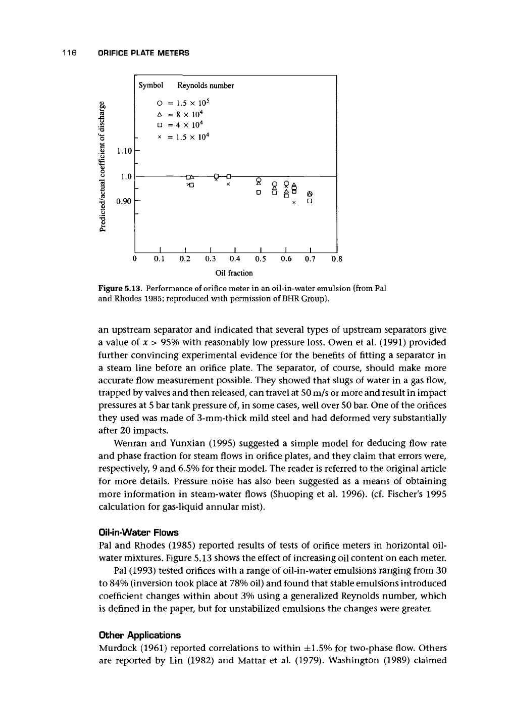
Figure 5.13. Performance of orifice meter in an oil-in-water emulsion (from Pal
and Rhodes 1985; reproduced with permission of BHR Group).
an upstream separator and indicated that several types of upstream separators give
a value of x > 95% with reasonably low pressure loss. Owen et al. (1991) provided
further convincing experimental evidence for the benefits of fitting a separator in
a steam line before an orifice plate. The separator, of course, should make more
accurate flow measurement possible. They showed that slugs of water in a gas flow,
trapped by valves and then released, can travel at 50 m/s or more and result in impact
pressures at 5 bar tank pressure of, in some cases, well over 50 bar. One of the orifices
they used was made of 3-mm-thick mild steel and had deformed very substantially
after 20 impacts.
Wenran and Yunxian (1995) suggested a simple model for deducing flow rate
and phase fraction for steam flows in orifice plates, and they claim that errors were,
respectively, 9 and 6.5% for their model. The reader is referred to the original article
for more details. Pressure noise has also been suggested as a means of obtaining
more information in steam-water flows (Shuoping et al. 1996). (cf. Fischer's 1995
calculation for gas-liquid annular mist).
Oil-in-Water Flows
Pal and Rhodes (1985) reported results of tests of orifice meters in horizontal oil-
water mixtures. Figure 5.13 shows the effect of increasing oil content on each meter.
Pal (1993) tested orifices with a range of oil-in-water emulsions ranging from 30
to 84% (inversion took place at
78%
oil) and found that stable emulsions introduced
coefficient changes within about 3% using a generalized Reynolds number, which
is defined in the paper, but for unstabilized emulsions the changes were greater.
Other Applications
Murdock (1961) reported correlations to within ±1.5% for two-phase flow. Others
are reported by Lin (1982) and Mattar et al. (1979). Washington (1989) claimed