Baker R.C. Flow Measurement Handbook: Industrial Designs, Operating Principles, Performance, and Applications
Подождите немного. Документ загружается.

5.2 ESSENTIAL BACKGROUND EQUATIONS 97
for those concerned with the design, installation, and maintenance of orifice plate
meters.
5.2 ESSENTIAL BACKGROUND EQUATIONS
Mass Flow Rate Equation
The mass flow rate is related to the differential pressure by the equation (c.f. Equa-
tion 2.11 for flow without loss)
q
m
= f (5.1)
where C is the coefficient of discharge, E is the velocity of approach factor
(1 -
P
4
)~
1/2
where p is the diameter ratio d/D of orifice diameter to pipe internal
diameter, e is the expansibility (or expansion) factor, Ap is the differential pressure,
and pi is the density at the upstream pressure tapping cross-section. The value of
the volumetric flow can be obtained from this using the relationship:
<7v
= q
m
/p (5.2)
where p is the density of the fluid at the appropriate conditions of pressure and
temperature.
Coefficient of Discharge
A simple expression for the discharge coefficient is
C
=
Coo +
&
(5>3)
where C^ is the coefficient for infinite Reynolds number, C
Re
is a constant for a par-
ticular installation, Re is the Reynolds number based on the pipe internal diameter,
and n is the index to which this is raised. The relative simplicity of Equation 5.3
is not matched by the most commonly used expressions for C, C^ or C
Re
either in
their complexity or variety.
The development of the equation commonly referred to as the API or AGA equa-
tion can be found by referring to Bean (1971) and Spitzer (1991). Reader-Harris and
Sattary (1990, cf. Reader-Harris 1989) reported that a joint meeting of European
Community and American Petroleum Institute (API) flow measurement experts in
New Orleans in November 1988 unanimously accepted a new equation. API 2530
was revised to include the Reader-Harris/Gallagher equation. This allowed for an
additional term for small pipes. Additional data have now allowed an adjustment
to the equation for small orifice diameters. This was reported by Reader-Harris et al.
(1995).
The previous coefficient of discharge adopted by the ISO and British Standards
Institution was given by an equation due to Stolz (1978, 1988). This equation was
retained in the standard until 1998. For details of the thorough work that has taken
place in the last 10 years or so, the reader is referred to Reader-Harris et al. (1995)
and Spencer (1993) (cf. Fling and Whetstone 1985).
98 ORIFICE PLATE METERS
The result is that current American practice appears to be to use API Chap-
ter 14 Section 3 (14.3) and a new expression for the discharge coefficient C has
been adopted by ISO, the Reader-Harris/Gallagher equation. However, the reader is
advised to refer to the document most appropriate to the application.
The form of these new equations is
C = Coo + jT-fi + Craps + Csmall orifice (5.4)
where all coefficients are functions of p. Craps includes values of L\ = l\/D and l\
is the distance of the upstream tapping from the upstream face of the plate, and
L'
2
=
l
f
2
/D
and
V
2
is the distance of the downstream tapping from the downstream
face of the plate. The prime signifies that the measurement is from the downstream
and not the upstream face of the plate. C
Re
reflects the slope of the characteristic due
to change of Re.
I have decided to include the provisional form of the equation in Appendix 5.A.
However, it is essential that the reader refers to the standard document to check
the latest version adopted in the United States, United Kingdom, or elsewhere and
to obtain all the conditions necessary for its valid use. These include ranges for
parameters, detailed design, pipe smoothness, etc.
The data for the new equation appear to have been obtained for orifice plates with
diameter ratios 0.1-0.75, throat Reynolds numbers from 1700 to 5 x 10
7
, and pipe
diameters from 50 to 250 mm. Data points for orifice diameters less than 12.5 mm
were very scattered and were not included.
The uncertainty is in the range 0.5-0.75% for D > 71.12 mm, and the precise
value depends on p. For small orifices, an additional uncertainty is combined arith-
metically and can be of order 0.4% for D = 25.4 mm (1 in.).
Miller (1996) gave the proposed Stolz II and NEL/TC 28 equations and tabulated
the values for these compared with ISO and
ANSI/API.
Perusal of the variation across
all equations is quite instructive.
A
difference between the new equations of at least
0.15%
is quite common, with differences occasionally as high as 1% for Re = 5,000.
Comparison of both old and both new gives a spread of discharge coefficients of
less than 0.1% to nearly 2%. The best agreement appears to be for p = 0.5 and
Re > 10,000, where variation across all four equations is less than 0.1% to about
0.5%.
One benefit, therefore, of the extensive work on refining equations has been
to increase our confidence in existing values of the discharge coefficient and in
indicating where the main divergences from these occur. Spitzer, also, makes the
point that the actual maximum variation in discharge coefficient obtained from the
main equations for a range of Reynolds numbers from 20,000 to 2,000,000 is only of
order 0.12%. For a p
=
0.5,
Re = 10
6
, and corner tappings, I estimate that the value of
C for the latest version of ISO is about 0.13% greater than for Stolz, which generally
confirms Spitzer's comments.
Expansibility Factor
The expansibility (expansion) factor provides an adjustment factor to allow differen-
tial pressure devices to be calibrated on water, an essentially incompressible fluid for
these purposes, for use on compressible gas. It, essentially, provides an adjustment
factor to the coefficient of discharge that allows for the compressibility of the gas.
5.2 ESSENTIAL BACKGROUND EQUATIONS 99
Reader-Harris (1998) provides a review of the past development of this factor and
the current recommended equation for it. It is found to be virtually independent of
Reynolds number. For many years, it was given by an equation of the form:
e
l =
l-(a
€
+b
€
p
4
)^- (5.5)
where a
€
and b
€
are constant coefficients, K is the isentropic exponent, which for
an ideal gas is equal to y, the ratio of specific heats, and if K is not known y
should be used, pi is the pressure at the upstream tapping. However, according to
Kinghorn (1986) the coefficients in common use in Equation (5.5) were probably in
error.
In the most recent version of the standard, a new equation for e
x
is given but
may be due for a further update. It is of the form
(5.6)
provided that pi/pi > 0.75. c
€
is another constant coefficient. The final bracket may
be approximated by Ap/icpi if
P2/P1
is very close to unity, but the work of Reader-
Harris (1998) suggests that the expression in the final bracket is preferable. He gave
the following equation, following careful analysis of the data, which may now be in
the latest ISO standard:
€i = l- (0.351 + 0.2S6p
4
+ 0.93£
8
)| 1 - (^) \ (5.7)
He gave a relative uncertainty for e\ of 3.5Ap/Kpi %, which differs slightly in de-
tail from that in
ISO.
He also gave
a
very useful theoretical derivation and obtained an
equation that differs from Equation (5.7) by about the uncertainty in Equation (5.7).
Pressure Loss
The expression in the ISO standard for the pressure loss across the orifice plate now
appears to be
Pressure
loss.
^jg^-C^
Jlp\\C
2
) +
Cp
2
Taking a typical value of C of about 0.6, this results in a pressure loss for a plate
with p = 0.5 (and E =
1.033)
of about 0.73Ap [cf. Urner 1997 who suggested that
the previous ISO equation (for nozzles and orifice plates) gives anomalous results if
used outside the limits of applicability of the ISO standard].
An alternative for orifice plates allowed by a recent version of the standard is
Pressure loss « (1 -
p
19
)Ap
(5.9)
which, for the preceding case, also gives 0.73Ap.
The most recent version appears to have provided a loss coefficient K given by
K = **»»*
1OSS
(5.10)
^PV
2
100 ORIFICE PLATE METERS
where
One of the most welcome changes in the latest version of the standard is the elimi-
nation of the symbol a, the flow coefficient, which was of little value. It has been
replaced by
CE,
to which it was equal, or other equivalent expression.
5.3 DESIGN DETAILS
Design details are set out fully in the ISO 5167 standard. It is important that the
detailed requirements are followed so that performance can be predicted, but also
so that new data can be added to existing data, to increase our overall knowledge.
In this book, some of the requirements will be touched on, but the standard should
be referred to for full details.
The design is, of necessity, an iterative procedure starting from the known re-
quirements of, typically, design flow rate, pipe size, and differential pressure. Danen
(1985) gives some helpful calculation flowcharts for each type of differential meter.
The first educated guess will relate to the value of p. With this and the selected values,
a new value of p is found via the flow rate equation. Iteration continues until a satis-
factory value of p is achieved. However, it is likely that most users will have access to
a computer program for this procedure (either from a manufacturer or in their own
software library) that will enable the optimum size of plate to be obtained. These
will ensure a balance between too great a pressure drop through the plate and too
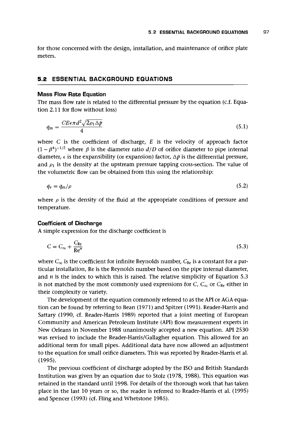
small a differential pressure for measurement. It is often suggested (Miller 1996) that
the pressure drop across the orifice plate should be of the order of 100 in. of water
(2.5 m or 25 kPa) and that the beta ratio should be close to 0.5. In some cases, this
may not be achievable. The pressure loss can never exceed the difference between
supply and demand pressures, and the minimum pressure should be kept above the
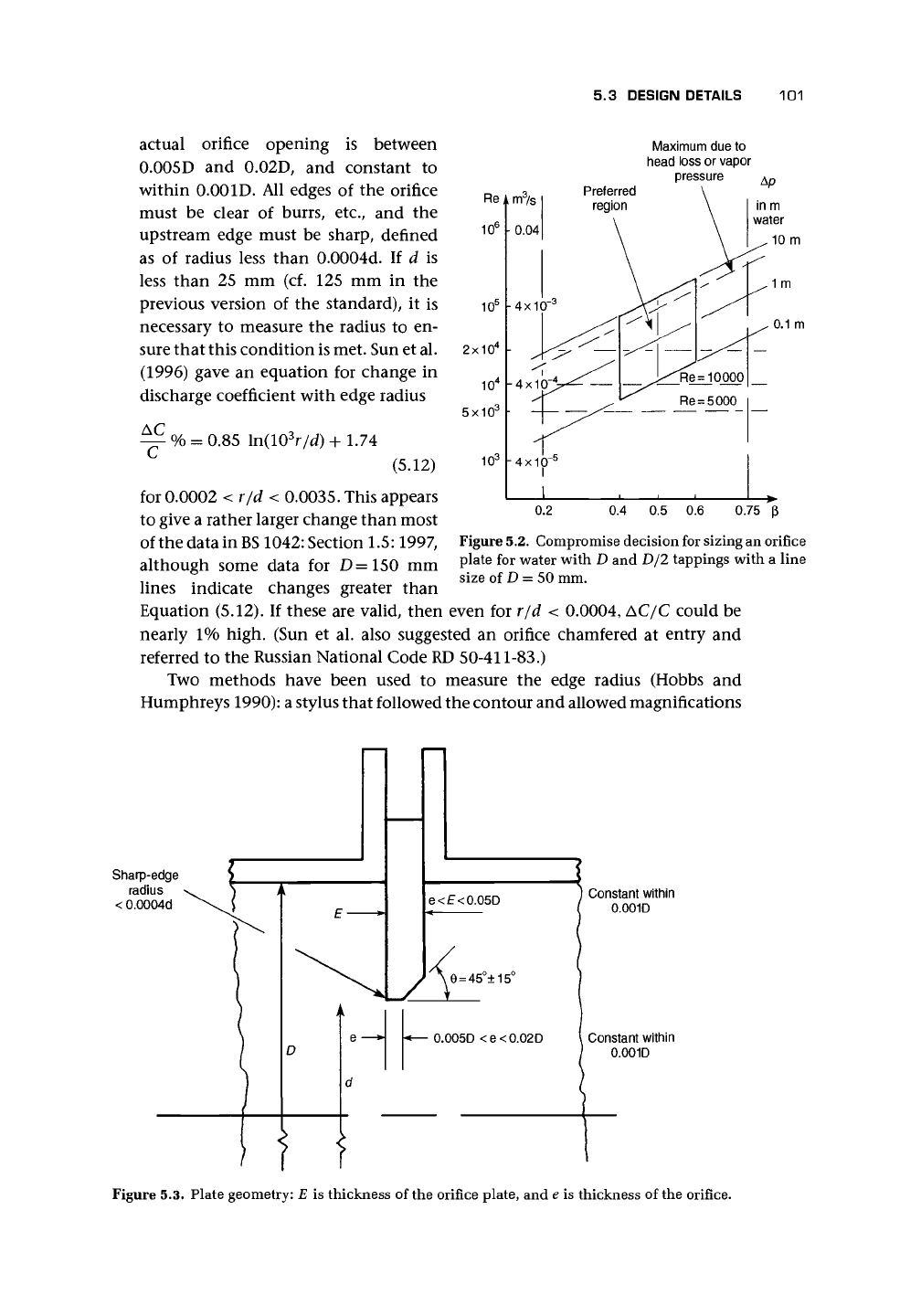
liquid's vapor pressure to avoid cavitation. Figure 5.2, which has been suggested in
various forms by various people, illustrates the compromise decision that needs to
be made between these factors.
For wide-range metering, Miller suggests the use of two transmitters ranged for
180 in. of water (4.5 m and 45 kPa) and 20 in. of water (0.5 m and 5 kPa).
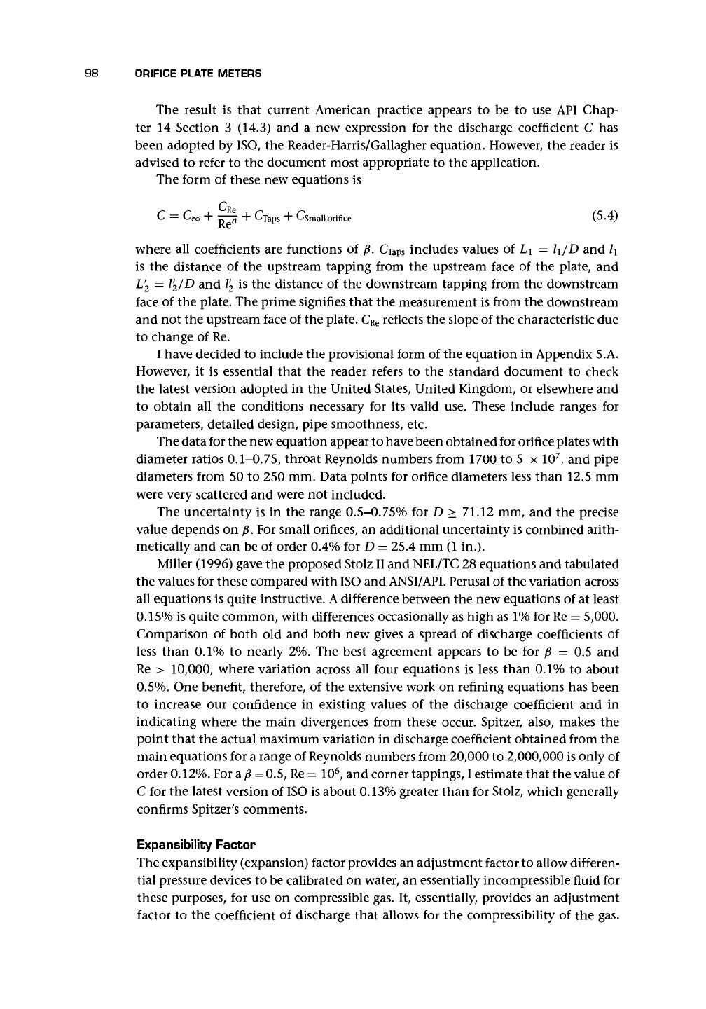
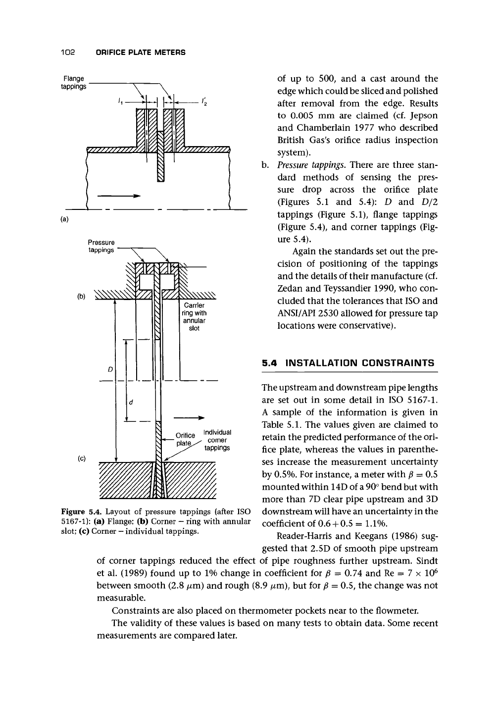
a. The plate. Some details of the plate geometry are shown in Figure 5.3 for a pipe of
diameter D and with an orifice diameter of
d.
The plate must be flat with parallel
faces,
and concentric. Flatness is defined in the standards. The upstream face is
the most critical because this has a strong effect on the flow entering the orifice.
In addition to the flatness, the plate must have a roughness of less than 10~
4
d.
It is useful to indicate the correct flow direction on the plate in a position that
can be seen when the plate is installed. The plate may have to be rather thick to
withstand the forces due to the flow, and in this case the downstream edge of
the orifice is beveled at an angle of 45° ± 15°, so that the final thickness of the
5.3 DESIGN DETAILS
101
actual orifice opening is between
0.005D and 0.02D, and constant to
within 0.001D. All edges of the orifice
must be clear of burrs, etc., and the
upstream edge must be sharp, defined
as of radius less than 0.0004d. If d is
less than 25 mm (cf. 125 mm in the
previous version of the standard), it is
necessary to measure the radius to en-
sure that this condition is met. Sun et al.
(1996) gave an equation for change in
discharge coefficient with edge radius
^ % = 0.85 ln(10
3
r/d) + 1.74
(5.12)
for 0.0002 < r/d < 0.0035. This appears
to give a rather larger change than most
of the data in
BS
1042: Section 1.5:1997,
although some data for D=150 mm
lines indicate changes greater than
Re
Preferred
region
Maximum due to
head loss or vapor
pressure
Ap
in m
water
10 m
0.1 m
Figure 5.2. Compromise decision for sizing an orifice
plate for water with D and D/2 tappings with a line
size of D = 50 mm.
Equation (5.12). If these are valid, then even for r/d < 0.0004, AC/C could be
nearly 1% high. (Sun et al. also suggested an orifice chamfered at entry and
referred to the Russian National Code RD 50-411-83.)
Two methods have been used to measure the edge radius (Hobbs and
Humphreys 1990): a stylus that followed the contour and allowed magnifications
Sharp-edge
radius
< 0.0004d
e<£<0.05D
• 0.005D <e<0.02D
Constant within
0.001D
f
f
Constant within
0.001D
Figure 5.3. Plate geometry: E is thickness of the orifice plate, and e is thickness of the orifice.
102 ORIFICE PLATE METERS
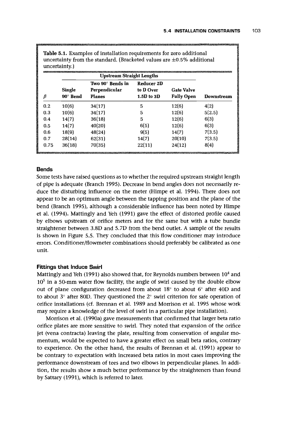
Flange
tappings
Pressure
tappings
(b)
(c)
Carrier
ring with
annular
slot
of up to 500, and a cast around the
edge which could be sliced and polished
after removal from the edge. Results
to 0.005 mm are claimed (cf. Jepson
and Chamberlain 1977 who described
British Gas's orifice radius inspection
system).
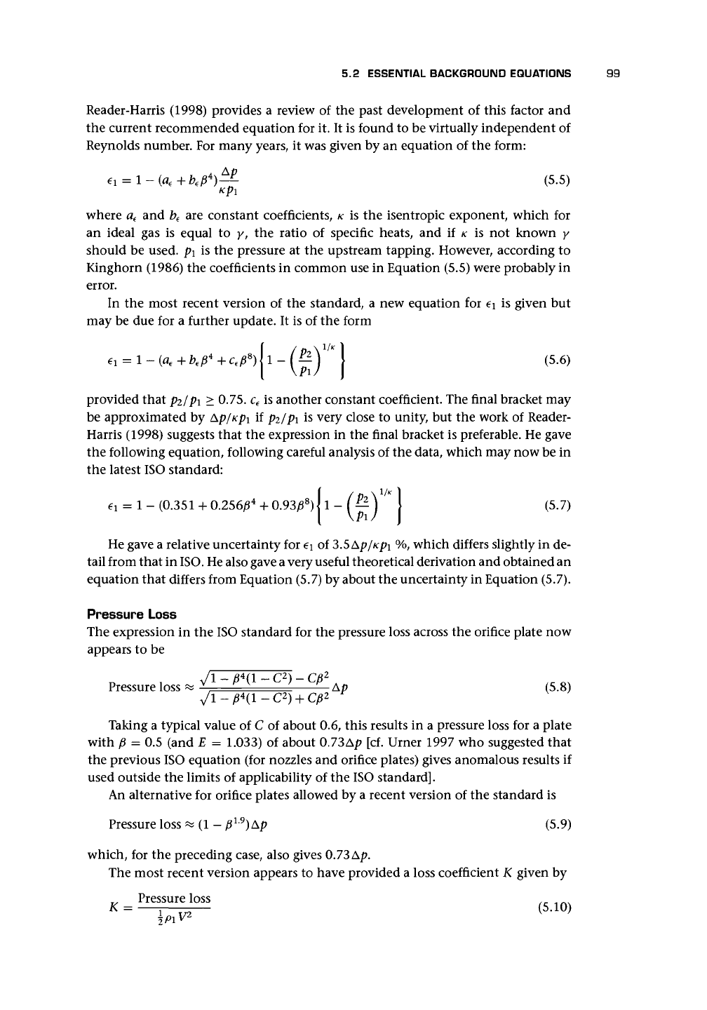
b.
Pressure
tappings.
There are three stan-
dard methods of sensing the pres-
sure drop across the orifice plate
(Figures 5.1 and 5.4): D and D/2
tappings (Figure 5.1), flange tappings
(Figure 5.4), and corner tappings (Fig-
ure 5.4).
Again the standards set out the pre-
cision of positioning of the tappings
and the details of their manufacture (cf.
Zedan and Teyssandier 1990, who con-
cluded that the tolerances that ISO and
ANSI/API 2530 allowed for pressure tap
locations were conservative).
5.4 INSTALLATION CONSTRAINTS
The upstream and downstream pipe lengths
are set out in some detail in ISO
5167-1.
A sample of the information is given in
Table 5.1. The values given are claimed to
retain the predicted performance of the ori-
fice plate, whereas the values in parenthe-
ses increase the measurement uncertainty
by
0.5%.
For instance, a meter with ft = 0.5
mounted within 14D of
a
90° bend but with
more than 7D clear pipe upstream and 3D
downstream will have an uncertainty in the
coefficient of 0.6 + 0.5 = 1.1%.
Reader-Harris and Keegans (1986) sug-
gested that 2.5D of smooth pipe upstream
of corner tappings reduced the effect of pipe roughness further upstream. Sindt
et al. (1989) found up to 1% change in coefficient for p = 0.74 and Re = 7 x 10
6
between smooth (2.8 /xm) and rough (8.9 /xm), but for p = 0.5, the change was not
measurable.
Constraints are also placed on thermometer pockets near to the flowmeter.
The validity of these values is based on many tests to obtain data. Some recent
measurements are compared later.
Figure 5.4. Layout of pressure tappings (after ISO
5167-1): (a) Flange; (b) Corner
—
ring with annular
slot; (c) Corner
—
individual tappings.
5.4 INSTALLATION CONSTRAINTS
103
Table 5.1. Examples of installation requirements for zero additional
uncertainty from the standard. (Bracketed values are ±0.5% additional
uncertainty.)
1
""""
i
i
1
p
1 0.2
1 0.3
1 0.4
1 0.5
1
0<6
1 0.7
| 0.75
Single
90° Bend
10(6)
10(6}
14(7)
14(7)
18(9)
28(14)
36(18)
Upstream Straight Lengths
Two 90° Bends in
Perpendicular
Planes
34(17)
34(17)
36(18)
40(20)
48(24)
62(31)
70(35)
Reducer 2D
to D Over
1.5D to 3D
5
5
5
6(5)
9(5)
14(7)
22(11)
Gate Valve
Fully Open
12(6)
12(6)
12(6)
12(6)
14(7)
20(10)
24(12)
Downstream
4(2)
5(2.5)
6(3)
6(3)
7(3.5)
7(3.5)
8(4)
Bends
Some tests have raised questions as to whether the required upstream straight length
of pipe is adequate (Branch 1995). Decrease in bend angles does not necessarily re-
duce the disturbing influence on the meter (Himpe et al. 1994). There does not
appear to be an optimum angle between the tapping position and the plane of the
bend (Branch 1995), although a considerable influence has been noted by Himpe
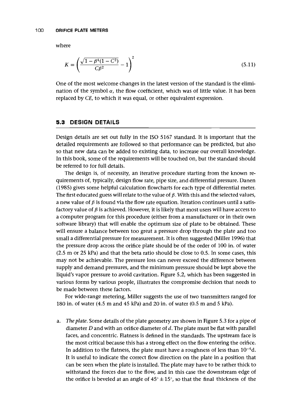
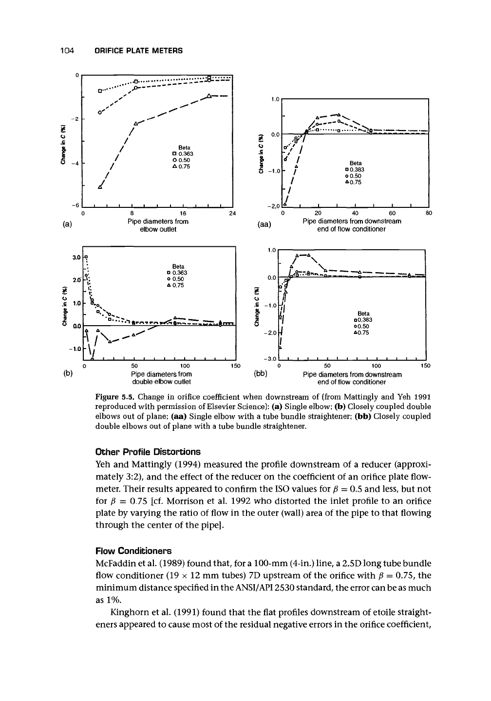
et al. (1994). Mattingly and Yeh (1991) gave the effect of distorted profile caused
by elbows upstream of orifice meters and for the same but with a tube bundle
straightener between 3.8D and 5.7D from the bend outlet. A sample of the results
is shown in Figure 5.5. They concluded that this flow conditioner may introduce
errors.
Conditioner/flowmeter combinations should preferably be calibrated as one
unit.
Fittings that Induce Swirl
Mattingly and Yeh (1991) also showed that, for Reynolds numbers between 10
4
and
10
5
in a 50-mm water flow facility, the angle of swirl caused by the double elbow
out of plane configuration decreased from about 18° to about 6° after 40D and
to about 3° after 80D. They questioned the 2° swirl criterion for safe operation of
orifice installations (cf. Brennan et al. 1989 and Morrison et al. 1995 whose work
may require a knowledge of the level of swirl in a particular pipe installation).
Morrison et al. (1990a) gave measurements that confirmed that larger beta ratio
orifice plates are more sensitive to swirl. They noted that expansion of the orifice
jet (vena contracta) leaving the plate, resulting from conservation of angular mo-
mentum, would be expected to have a greater effect on small beta ratios, contrary
to experience. On the other hand, the results of Brennan et al. (1991) appear to
be contrary to expectation with increased beta ratios in most cases improving the
performance downstream of tees and two elbows in perpendicular planes. In addi-
tion, the results show a much better performance by the straighteners than found
by Sattary (1991), which is referred to later.
104
ORIFICE PLATE METERS
*
.E
/
/
/
/
• /
i i i i i
Beta
D 0.363
0 0.50
A
0.75
i i i i i i
(a)
8 16
Pipe diameters from
elbow outlet
3.0
2.0 -'
.£ 1.0
0.0
-1.0 -
•
-
V^
"V,
Beta
Q 0.363
0 0.50
A
0.75
(b)
50 100
Pipe diameters from
double elbow outlet
.£
O -1.0
-2.0
(aa)
20 40 60
Pipe diameters from downstream
end of flow conditioner
(bb)
50 100
Pipe diameters from downstream
end of flow conditioner
Figure 5.5. Change in orifice coefficient when downstream of (from Mattingly and Yeh 1991
reproduced with permission of Elsevier Science): (a) Single elbow; (b) Closely coupled double
elbows out of plane; (aa) Single elbow with a tube bundle straightener; (bb) Closely coupled
double elbows out of plane with a tube bundle straightener.
Other Profile Distortions
Yeh and Mattingly (1994) measured the profile downstream of a reducer (approxi-
mately 3:2), and the effect of the reducer on the coefficient of an orifice plate flow-
meter. Their results appeared to confirm the ISO values for
f$
= 0.5 and less, but not
for p
—
0.75 [cf. Morrison et al. 1992 who distorted the inlet profile to an orifice
plate by varying the ratio of flow in the outer (wall) area of the pipe to that flowing
through the center of the
pipe].
Flow Conditioners
McFaddin et
al.
(1989) found that, for a 100-mm (4-in.) line, a 2.5D long tube bundle
flow conditioner (19 x 12 mm tubes) 7D upstream of the orifice with fi = 0.75, the
minimum distance specified in the ANSI/API 2530 standard, the error can be as much
as 1%.
Kinghorn et al. (1991) found that the flat profiles downstream of etoile straight-
eners appeared to cause most of the residual negative errors in the orifice coefficient,
5.4 INSTALLATION CONSTRAINTS 105
as opposed to the positive errors due to swirling flow. To ensure an error of less than
±0.5%,
a straightener ID long should be placed upstream at least
• 6D for plates with a beta ratio of 0.5 and
• 14D for plates with a beta ratio of 0.8.
Even with 16D separation, virtually all tests suggested some effect from the straight-
ener.
Karnik et al. (1994) tested the effect of a 19-tube bundle in a 101.6-mm line
for good flow conditions and downstream of an elbow and looked at the effect on
an orifice plate. Their results are very interesting in showing that even though the
profile from the tube bundle at about 20D was very close to the fully developed
turbulent profile, approximating to Equation (2.4) with n = 7
A,
the turbulence
intensity pattern is markedly different, suggesting that this is a factor in the re-
sponse of orifice plates. They showed that the orifice coefficient downstream of the
elbow and the tube bundle, compared with the correct value, was high by about
0.2% between 10D and 15D and fell to about
0.1%
high by about 20D. There was a
point closer to the orifice plate where the coefficients were approximately the same,
but it would be unwise to rely on this for precise measurements (cf. Morrow et al.
1991 who used an arrangement that allowed them to slide a tube bundle condi-
tioner along the pipe between a 90° long-radius bend and an orifice plate to obtain
the variation of discharge coefficient with position for a gas flow. Overall the re-
sults appeared to suggest that, if possible, the conditioner should be next to the
bend.)
Sattary (1991) concluded from the EEC orifice plate program on installation
effects that the ISO 5167 and AGA Report No 3 minimum straight length specifica-
tions needed to be revised. The results for conditioners 19D upstream of an orifice
in fully developed flows showed shifts of up to 0.33-0.5% for p = 0.57, rising to
about 0.57-0.75% for p = 0.75. For a p = 0.2, there was negligible effect from a
tube-bundle conditioner at 5D. The reader concerned with this topic is encouraged
to refer to the original paper, which has extensive experimental data and indications
that there is variation between the performances of the various straighteners. There
is some discrepancy between the various standards. For two bends in perpendicular
planes, by far the most serious disturbance, the ISO requirement for no loss in ac-
curacy is that the orifice should be at least 44D downstream for a p = 0.55 and 70D
for a p = 0.75. On the other hand, the blanket requirement for a flow straightener
is that there should be at least 20D from the fitting to the straightener and at least
22D from the straightener to the meter. This is a total of at least 42D plus the length
of the straightener, and greater than or equal to all other requirements for p up to
0.75,
apart from those for two or more bends in different planes. The equivalent
values for AGA for two bends or tees not in the same plane are (Sattary 1991) for
P =
0.57, 23.5D, and for p
=
0.75, 35.5D, and with a short tube bundle straightener
for the general case is 17D (straightener distance 5.5D + installation distance 11.5D).
Sattary's results appeared to suggest that the values without straightener were not
conclusive for ISO, but, apart from the two bends in perpendicular planes, the AGA
lengths may be too short.
106 ORIFICE PLATE METERS
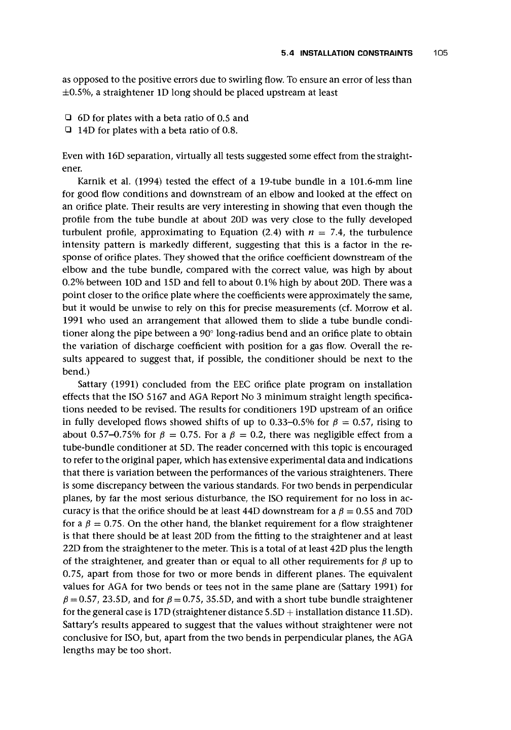
Orifice Plates
•I Direction of flow
_ JL JL _JL _J
Figure 5.6. Other orifices (reproduced with permission of
Elsag
Bailey-Bush Beach Engineering
Division).
5.5 OTHER ORIFICE PLATES
Figure 5.6 gives a range of orifices that are useful for special purposes, data for some
of which may be obtained from
BS
1042 Section 1.2: 1989.
The
quarter circle (quadrant) orifi
ceplate is for low Reynolds number flows, which
result from high viscosity liquids. The entry is more difficult to make precisely
than that of the square-edged orifice, and manufacturing tolerances are there-
fore critical. An expression for the discharge coefficient in the standard has an
uncertainty in the region of 2-2.5%.
The
conical entrance
design is for very low Reynolds number flows, which result
from very high viscosity liquids. The entry is again more difficult to make
precisely than that of the square-edged orifice, and manufacturing tolerances
are therefore critical. Provided that the standard is followed, C = 0.734 with
uncertainty of 2%.
Eccentric
and
chordal (segmental) orifices
are more suitable for flows that have a
second component in them. Of these, the eccentric orifice plate is preferred,
presumably on grounds of more accurate manufacture and more flexible sizing
and of being defined in the standard. Thus for a liquid with solid matter, one
would choose an eccentric orifice with the hole at the bottom of the pipe,
whereas for a liquid with gas entrained, an orifice at the top of the pipe would
be chosen. For p in the range 0.46-0.84, the standard gives the coefficient in
the range 0.597-0.629 with an uncertainty in the region of 1-2%. In cases
where the position of the second component is not clear, it may be necessary
to go to a chordal orifice with the edge vertical to allow the second component
to pass wherever it is in the pipe.
Ball
orifices
(see Chapter 8).
Slotted orifices
(see Chapter 8).
5.6 DEFLECTION OF ORIFICE PLATE AT HIGH PRESSURE
Jepson and Chipchase (1975) provided a formula to calculate the deflection in the
downstream direction and consequent error for plates operating at high pressure.