Bayer R.G. Mechanical Wear Fundamentals and Testing, Revised and Expanded
Подождите немного. Документ загружается.

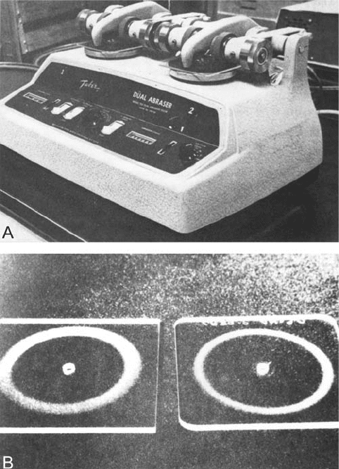
a Taber Abraser (ASTM D1044) (Fig. 9.94) correl ate well with the Brush Test (105). The
test with the Taber Abraser provides a dry, two-body abrasive wear condition.
The common or basic element in these two tests is a mild abrasive wear, which appears to be
the controlling factor in this type of application. This is to be expected since corrosive wear
should not be a significant element in the wear of these coating materials in these
applications, based on their properties.
9.3.9. Drill Wear Tests
Controlled drilling is a frequently used approach to address drill wear concerns
(106,107). These tests consist of sequential hole drilling in a control led work piece at a
controlled speed, depth, and feed rate. The number of holes that can be drilled before fail-
ure determines the wear life of the drill. Several criteria for failure are used, depending
somewhat on the type of drilling being done. One general type of criteria is the quality
of the hole being drilled including hole dimensions, hole appearance, smear, and rough-
ness. Periodic measurements or inspection of the holes are performed with these type of
criteria. Another type of criteria is associated with various attributes of the drilling
Figure 9.94 A commercial version of a Taber Abraser is shown in ‘‘A’’. ‘‘B’’ shows examples of the
wear scar produced in the test. (From Ref. 104, reprinted with permission from ASTM.)
Copyright 2004 by Marcel Dekker, Inc. All Rights Reserved.
processes. For example, the occurrence of squealing might be used to determine drill life.
Other criteria could be the occurrence of chatter, increased torque, temperature or drill
fracture. With all these criteria, drilling is continued until the event occurs and the number
of operations is used as a measure of performance. Frequently, several of these criteria
might be used with the nature of the failure changing with the drilling conditions or drill.
Tests of this nature are very operational in character, defining wear life in terms of
the number of holes that can be successfully drilled rather than directly in terms of wear.
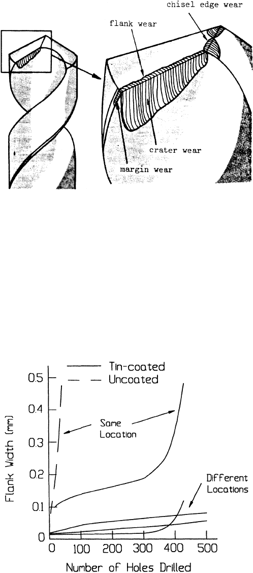
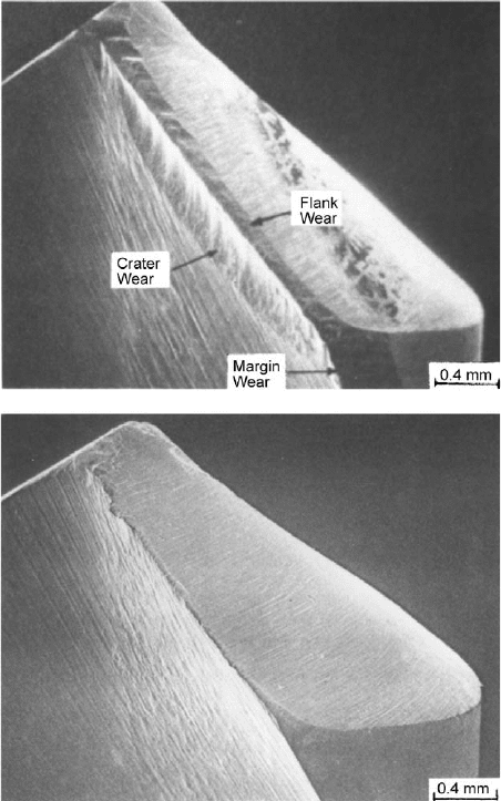
In fact, there are several wear points or zones associated with drills. The wear conditions
can be different at these points, and the wear at these points can have a diffe rent effect on
Figure 9.95 Twist drill geometry and location of wear zones. (From Ref. 107, reprinted with
permission from ASME.)
Figure 9.96 Wear curves for flank wear of twist drills. (From Ref. 105.)
Copyright 2004 by Marcel Dekker, Inc. All Rights Reserved.
performance. For example, the geometry of a twist drill, with the different wear zones
identified,isshowninFig.9.95
. The wear in each of these zones can also be addressed with
these tests, in addition to the overall wear behavior. Since the geometry of these regions
is complex, qualitative techniques are frequently used to evaluate the wear, such as SEM
and optical microscopy. Sometimes a linear dimension, such as scar width, can be
used to quantify the wear. Some quantitative wear data for flank wear are shown in
Fig.9.96
,andsomeSEMmicrographsofdrillwearscarsarepresentedinFig.9.97.
These tests are used not only to compare materials but also to investigate a wide vari-
etyofparametersassociatedwithdrillsanddrilling.Forexampledrillspeed,various
dimensions and angles of the drill, hole thickness, and work piece properties are para-
meters, which can be studied and evaluated in these tests. Some data from these types
ofstudiesareshowninFigs.9.98
and9.99, illustrating the way the data are analyzed
and presented with these types of tests.
Figure 9.97 Examples of the wear of twist drills. (From Ref. 106, reprinted with permission from
ASME.)
Copyright 2004 by Marcel Dekker, Inc. All Rights Reserved.
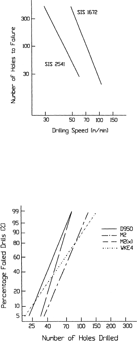
Figure 9.98 The effect of drill speed on drill life when drilling two different materials. (From
Ref. 107.)
Figure 9.99 The effect of different drill material on drill life. A statistical measure is used to
quantify performance in this case. (From Ref. 107.)
Copyright 2004 by Marcel Dekker, Inc. All Rights Reserved.
9.3.10. Seal Wear Tests
There are several aspects of the wear of seals that are of significance. One is directly related
to materials loss (e.g., changes in dimensions and clearances). Another is changes in
surface roughness, and the third can be the formation of trans fer or third body films. All
three can individually and jointly influence sealing and cause functional failure, namely
leakage. All of these aspects can be influenced by the operational conditions associated
with the applic ation. Because of this complex relationship between wear and function,
it is desirable to evaluate seal wear under highly simulative conditions in an operational
type test (108). An example of this type of test is one that was used to investigate
seals for Stirling engines (109).
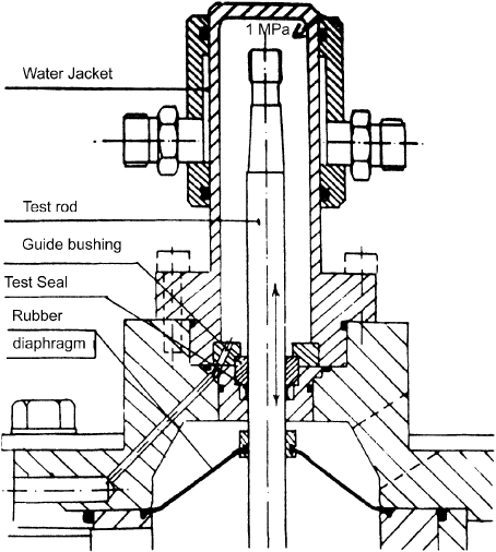
Across-sectionofthetestapparatusisshowninFig.9.100
. It replicates the sealing
conditions of the engine rod, with the exception that inert gas at a fixed pressure is used to
simulate the conditions in the combustion chamber. The fixed pressure is selected to be
representative of the average pressure in the chamber under some generic operating con-
ditions (e.g., highw ay or urban travel conditions). The other parameters, such as rpm,
stroke length, speed, and temperature, are selected to be representative of the application
and can be varied to represent different conditions of operation . The apparatus can
accommodate different materials and design parameters. It was also designed so that
leakage measurements, as well as seal temperature measurements, could be made. Thus,
this apparatus can be used in the evaluation of a wide range of material, design, and use
factors in terms of their effects on seal wear performance.
Figure 9.100 Diagram of an apparatus used to evaluate the wear of seal material. (From Ref. 134,
reprinted with permission from ASME.)
Copyright 2004 by Marcel Dekker, Inc. All Rights Reserved.

The basic methodology of the test is to run the apparatus for a specific length of time
and to monitor leakage and tempe rature during that period. At the end of the complete
test duration, the samples are removed and examined for wear. This included profilometer
measurements of roughness, mass loss of the seals, and other characterizations of the rub-
bing surfaces, such as optical and SEM examinations. The type of quantitative data gen-
eratedinthistestisshowninTable9.8
. Leakage is considered to be the primary criteria
for wear. The other measurements and observations aid in identifying the particular fail-
ure mode and differences in wear behavior. For example, in this study, it was concluded
that the plasma-sprayed Mo coating performed the best, primarily because it maintained
its roughness and allowed the formation of a very stable polytetrafluoroethene (PTFE)
transfer film.
While this test provides good simulation of most of the aspects and allows wear phe-
nomena to be correlated with performance (i.e., leakage), it does not provide complete
simulation. Combustion doe s not occur, only the mean pressure of the duty cycle is simu-
lated. As a consequence, this test is used to select material and design parameters for eva-
luation in a more simulative test in a laboratory engine. At the same time, more
phenomenological type wear tests are used to identify promising candidates for this inter-
mediate seal test (110). This is an example of a staged or multilevel testing program, with
each level serving as a screen for selecting material s for the next and more simulative test.
9.3.11. Wear Test for a Magnetic Sensor
In this application, pieces of encoded magnetic tape are attached to or mounted on a vari-
ety of items, such as boxes, pack ages, or routing documents. To read the information, a
Table 9.8 DataObtainedinSealwearTestUsedtoSimulate the Stirling Engine Application
Rod surface
Time
(hr)
Rod
temp.
(
C)
N
2
leakage
(1=hr)
Initial
roughness
(R
a
mm)
Final
roughness
(R
a
mm)
Hardness
(HV 1)
Wear
rate
(mg=h) Comments
Nitrided Steel 78 55 1.3 0.06 0.03 1127 0.105
88 71 2.8 0.25 0.09 1162 0.132
70 47 7.3 0.04 0.14
a
1132 0.250 Wavy
a
Plasma sprayed 71 64 2.1 0.22 0.18 530 0.107
molybdenum 70 67 2.9 0.21 0.31 589 0.110
70 74 1.7 0.24 0.18 620 0.117
Plasma sprayed 71 47 3.1 0.26 0.09 708
a
0.086 Uncertain
a
aluminium
oxide
70 51 4.9 0.43 0.26 680 0.033
Plasma sprayed
chromium
oxide
70 58 13.6 0.65 0.55 617 0.343
Nedox 70 56 14.9 0.22
a
739 0.409 Very Wavy
a
Hard chromium
on zinc
70 56 13.1 0.31 0.01 1039 0.554
Seal material: Rulon LD.
Source: Ref. 134.
Copyright 2004 by Marcel Dekker, Inc. All Rights Reserved.
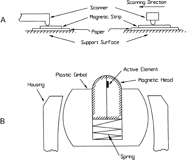
magnetic head or sensor is pressed up against the surface of the tape section with a hand-
held scanner and moved across the surface of the tape. A use for such a scanner is at the
checkout station of a retail store, serving a simila r purpose to the bar code readers found
in many supermarkets. However, the magnetic tape may contain more information than
provided by the bar code. Another use is to monitor the flow of materials through a man-
ufacturing plant. In this case, the magnetic code not only provides infor mation regarding
identification but also about processing steps, etc. The scanning situation in these types of
applicationsisillustratedinFig.9.101
, along with a diagram of the magnetic head that
was used.
The basic wear situation is similar to but significantly different than that encountered
with more typical uses of magnetic tape (e.g., tape recorder and memory tape drives). Both
are concerned with the wear of the head by the magnetic tape, but there are differences in
speed and relative usage. Surface speeds are higher in magnetic recording. In both the head
surface experiences the greater amount of sliding but the tape surface experiences much
less use in this application than in recording and data storage applications. However,
the major difference is that in tape recorders and drives, the tape surface is relatively clean.
This is not the case in this sensor application since the tape surfaces are exposed to a wide
variety of environments, some of whi ch are quite dirty and contain very abrasive materi-
als. Examples of these types of environments would be that of an open manufa cturing or
machining area, or receiving and shipping bays. Sand, iron oxide particles, aluminum
oxide grit, and other abrasive particles are common in these environments (111). The
abrasive action of these particles collected by the tape surfaces can become the primary
Figure 9.101 ‘‘A’’ illustrates the use of a magnetic hand scanner in reading stored information on
magnetic strips located on labels, cards, and documents. ‘‘B’’ shows the design of the sensor in the
region of the magnetic head.
Copyright 2004 by Marcel Dekker, Inc. All Rights Reserved.
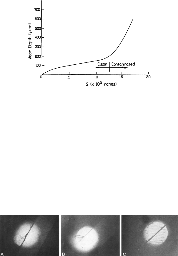
wear mode, masking the effect of the tape itself. Figure 9.102 shows the effect that contam-
ination can have on the wear of these sensors. To address this wear situation, a wear
test was developed that utilizes the drum configuration discussed previously in the
section on phenomenological tests (Sec. 9.2.12) (42).
The drum test configuration was selected for the same reason that it was developed
to address wear by paper and ribbon, namely that the tape surface wears more readily than
the heads. In this use of the device, the magnetic tape is wrapped around the surface of the
drum, and the magnetic head replaces the normal spherical wear specimen. To simulate
the action of the abrasive contamination of the tape surface in the application, the surface
of the tape is coated with different types and amounts of abrasive particles. This simu-
lation was verified early in the development of the test by comparing wear scars produced
in the field to those produced in the test for a variety of abrasive dust co atings on the
surfaceofthetape.Figure9.103
shows such a comparison. It was concluded that several
methods of coating could be used to provide simulation, and that the primary reason for
selectingoneortheotherwascontrolandeaseofapplication.AspraycoatingofAC
Fine
Test Dust, which is mainly sand (SiO
2
), and gelatin were selected for this purpose. This
technique provided a uniform coating of a brasive particles protruding above the surface
Figure 9.102 The effect of abrasive contamination on the wear of the magnetic head. (From Ref.
135.)
Figure 9.103 ‘‘A’’ shows an example of the wear morphology found on heads worn in field tests.
‘‘B’’ and ‘‘C’’ show examples of the morphology obtained in laboratory tests on tape surfaces con-
taminated with abrasives. (From Ref. 135, reprinted with permission from Elsevier Sequoia S.A.)
Copyright 2004 by Marcel Dekker, Inc. All Rights Reserved.
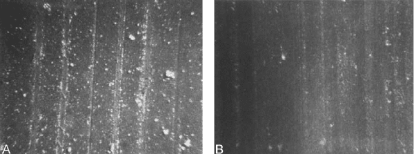
of the gelatin (Fig. 9.104). Tests were done to investigate the possible influence that the
gelatin might have on the wear. This was done by comparing wear behavior with this type
of coating to those without the gelatin, that is dust coated tapes. No difference was found.
Wear was found to depend solely on the amount, size, and nature of the
abrasives on the surface. This is probably because the gelatin layer is weak, allowing easy
movement of the particles, and thin enough not to mask or bury the particles. The gelatin
layer is less than 2 mm, while approximately 80% of the sand particles are greater than
2 mm. To insure consistency of these coati ngs a short test, which utilized only a small
portion of the tape, was conducted with a 52100 steel ball on each coated tape. If the
amount of wear in this test fell outside an acceptable range, the tape was not used.
Within the acceptable range, these same results provided a means to scale the individual
tests to improve resolution.
As was described in Sec. 9.2.12, the wear specimen moves across the surface of the
drum in an axial direction while the drum rotates, producing a helical path on the surface
of the drum. A high enough axial speed for the specimen can insure that the specimen is
always sliding on a new or fresh tape surface. Such a condition was used for most of the
evaluations done with this test. This eliminated the complexities introduced by changes in
the abrasive characteristics of the tape surface with wear. It also provided a worst case
situation, since the abrasivity of both the uncoated and coated tape surfaces tend to
decrease with wear. A standard drum rotational speed was also selected with two concerns
in mind. One was to maintain simulation. The other was to reduce test time. Similar wear
behavior was observed for surface speeds up to 300 cm=sec; however, testing with abrasive
coatings at the higher speeds produced temperature increases which were beyond those
found in the application. As a result, a speed more representative of the application and
one which did not produce a significant temperature rise was selected. The drum rotational
speed selected was 36 cm=sec and the specimen speed was 0.25 mm=rev or 0.02 mm= sec.
A gimbal-spring loaded mounting was used for the magnetic head in the application.
This insured that even though the sensor was hand-held a consistent load and proper
orientation would occur at the head=tape interface. A limited amount of testing was done
to characterize wear behavior as a function of load. However, the majority of the tests,
particularly those done to evaluate materials and design options, were done using the load
in the application, 50 gm.
The relative wear performance of the heads was measured in terms of the amount of
sliding under standard test conditions that was required to produce a 5-ohm change in the
resistance of the magnetic element, located beneath the surface (see Fig. 9.101). The 5-ohm
Figure 9.104 Examples of contaminated tape surfaces after a wear test. In ‘‘A’’, the tape was
coated with loose AC Fine Test Dust. In ‘‘B’’, the tape was coated with a mixture of AC Fine Test
Dust and gelatin. (From Ref. 135, reprinted with permission from Elsevier Sequoia S.A.)
Copyright 2004 by Marcel Dekker, Inc. All Rights Reserved.
change was a functional criteria for the device. Thi s was accomplished by monitoring this
resistance during the test and stopping the test when a change equal to or greater than
5 ohms occurred. An automatic system was developed for this. In these tests, as well as
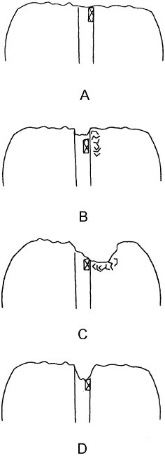
in the field, a 5-ohm change could be caused by several different phenomena which could
occur in the abrasive environment. This included gradual wear of the surfaces down to the
magnetic element, micro- and macro-fracture down to the element, and penetration by
abrasive particles of the seam between the two halves. These conditions are illustrated
inFig.9.105
. In most cases a combination of gradual wear, micro-fracture of the edges,
and penetration determined life. The relative contribution of each was assessed at the
end of the test by optical and SEM microscopy, and profilometer measurements. The pro-
filometer measurements were also used to estimate wear volume, which was normalized
with load and distance of sliding to provide a wear coefficient for the material and abra-
sive condition. With these types of tests, the evaluations of a wide variety of design and
manufacturing aspects were addressed. These included radius, load, magnetic element
location, material selection, adhesive thickness, deposition techniques for the magnetic
element, grinding and polishing of the head, environmental effects, and orientation of
the seam with sliding direction. The test was also used to precondition heads in a
controlled manner for use in corrosion evaluations.
Figure 9.105 Illustrations of the wear conditions found on heads.
Copyright 2004 by Marcel Dekker, Inc. All Rights Reserved.