Czichos H., Saito T., Smith L.E. (Eds.) Handbook of Metrology and Testing
Подождите немного. Документ загружается.

548 Part C Materials Properties Measurement
Table 10.2 (continued)
Measurement
principle
Measurement
range (limiting
quantities)
Measurement
sensitivity
Measure-
ment
repro-
ducibility
range (%)
Materials
specimen type
Specimen
geometry,
dimensions
Methods
merit
Methods
demerit
Moment-
measuring
coil
j
max
:
10
−4
–10
−2
Vsm
j:10
−10
Vsm j: 0.5–1 Bulk
permanent
magnets
Cylinders,
blocks,
rings,
segments
Fast and
accurate,
standard-
ized
Only for two
pole magnets,
one quantity
Pulse field
magnetometer
(PFM)
H
max
:4–8MA/m H:1kA/m
J:1mT
H, J: 1–3 Bulk
permanent
magnets
Cylinders,
blocks,
segments
High field
strength,
fast
Demagnetization
factor, eddy
currents to be
considered
DC hysteresis-
graph – ring
method
H
max
:
10–20 kA/m
H:0.01 A/m H:1
J: 1–2
Ferromagnetic,
sintered or
powder com-
pacted rings,
wound ring
cores
Rings
(geometries
with closed
magnetic
path),
stamped
stacks of
sheet
Many quan-
tities, very
low field
strength
possible,
standard-
ized
Requires
specimen
winding
DC hysteresis-
graph – yoke
methods
H
max
:
50–200 kA/m
H:1A/m H: 2–3
J: 1–2
Ferromagnetic
steel
Bars, strips
of sheet
Many
quantities,
standard-
ized
Restricted
specimen
dimensions
and shapes
Coercimeter H
max
:
20–200 kA/m
H:0.5–1A/m H
c
: 2–5 Ferromagnetic
steel
Components
of various
shapes
Various
specimen
shapes,
standard-
ized
Only one
quantity (H
c
)
AC hysteresis-
graph – ring
method
f :10Hz–1MHz H:0.01 A/m J: 1–10
H: 1–2
Ferromagnetic
materials
Rings
(geometries
with closed
magnetic
path),
stamped
stacks of
sheet
Many
quantities,
standard-
ized
Restricted
specimen
shape,
requires
specimen
winding
Epstein frame f :≤400 Hz
ˆ
J
max
:1.5–1.7T
J:1mT J: 2–3
P
w
: 2–7
Ferromagnetic
(electric) steel
Strips of
sheet
Standardized,
widespread
method
Demanding
specimen
preparation,
systematic
error
Single-sheet
tester (SST)
f : 50–400 Hz
ˆ
H
max
:1–10kA/m
ˆ
J
max
:0.8–1.8T
J:1mT J, H: 2–3
P
w
: 1–2
Ferromagnetic
(electric) steel
Sheet Standardized,
simple
specimen
preparation
Large
specimens in
standardized
version,
systematic
error
Wattmeter
method
ˆ
H
max
:1–10kA/m 2) 2) Ferromagnetic
(electric) steel
Rings,
sheet using
fixtures
Standardized
method
Few
quantities
Voltmeter–
ammeter
method
ˆ
H
max
:1–10kA/m 2) 2) Ferromagnetic
(electric) steel
Rings,
sheet using
fixtures
Fast, stan-
dardized
method,
common
instrumen-
tation
Few
quantities
Part C 10.2

Magnetic Properties 10.2 Soft and Hard Magnetic Materials: Measurement Techniques 549
Table 10.2 (continued)
Measurement
principle
Measurement
range (limiting
quantities)
Measurement
sensitivity
Measure-
ment
repro-
ducibility
range (%)
Materials
specimen
type
Specimen
geometry,
dimensions
Methods
merit
Methods
demerit
Saturation coil H: 100–900 kA/m
j
max
:
10
−4
–10
−2
Vsm
j:10
−10
Vsm j: 1–2 Nickel, Ni
alloys, Co
content in
hard metals
Discs, wire,
cylinders,
small
components
Fast, stan-
dardized
method
Only one
quantity, J
S
limit depends
on shape
Faraday scale H:
800–1600 kA/m
1) 1) Ferro-,
para- and
diamagnetic
materials
Small
massive
samples,
powders,
films
High
sensitivity,
wide
temperature
range, small
samples
Delicate,
costly instru-
mentation
Gouy scale H:
800–2400 kA/m
1
)
1
)
Para- and
diamagnetic
materials
Bars,
vessels with
liquids or
gasses
High
sensitivity,
wide
temperature
range
Often delicate
instrumenta-
tion, large
specimen
volume
Impedance
bridges
f : 1 Hz–100 MHz 2) 2) Ferro-
and ferri-
magnetic
materials
Rings,
components
Component
testing close
to electrical
application
Require
specimen
winding
1
)
mostly research instruments with differing ranges, sensitivities and reproducibility
2) strongly depending on capabilities of standard electrical instrumentation
calibrations and are widespread in application. The in-
formation is selected to allow an evaluation of the
methods. More details are given where errors are liable
to be introduced.
Section 10.2.3 is completed by a short description
of measuring methods for magnetostriction and, pro-
vided by Grössinger, nonstandard testing methods for
soft magnetic materials that are used in scientific re-
search laboratories.
10.2.2 Properties
of Hard Magnetic Materials
Hysteresisgraph for Hard Magnetic Materials
A very important instrument for the characterization
of bulk permanent magnets is the hysteresisgraph. It
is mainly used to record the second-quadrant hystere-
sis loop. From this, material parameters such as the
remanence B
r
, the maximum energy product (BH)
max
and the coercive field strengths (coercivities) H
cJ
and
H
cB
, can be determined. A measurement of recoil loops
allows the calculation of the recoil permeability μ
rec
.
The main components are an electromagnet to mag-
netize and demagnetize the specimen, measuring coils
for the field strength H and the polarization J and
two electronic integrators (fluxmeters) to integrate the
voltages induced in the coils. A typical configuration
of a computer-controlled hysteresisgraph is shown in
Fig. 10.2.
An electromagnet with a vertical magnetic-field di-
rection is used. The magnet specimen is placed on the
pole cap of the lower pole. The upper pole can be low-
ered to close the magnetic circuit.
While recording the hysteresis loop, high flux den-
sities are only required for relatively short time periods.
Therefore it is possible to avoid active cooling of the
electromagnet coils up to a peak electric power of
approximately 3 kW. If the electromagnet is designed
carefully, maximum flux densities of 1500–2400 kA/m
can be achieved for specimen heights of several mil-
limeters. Beyond this point, the steel parts of the
electromagnet frame become saturated. For a further in-
crease of the field strength significantly higher electric
power and water cooling become necessary.
The measuring principle is based on the fact that the
poles of the electromagnet form faces of equal mag-
netic potential. It is only under this condition that the
specimen is homogeneously magnetized and the field
strength that is measured next to the magnet is equal
to its inner field strength. The pole materials (soft mag-
Part C 10.2
550 Part C Materials Properties Measurement
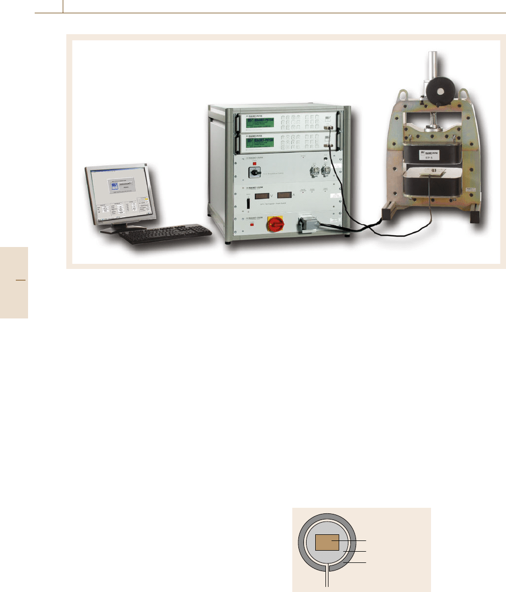
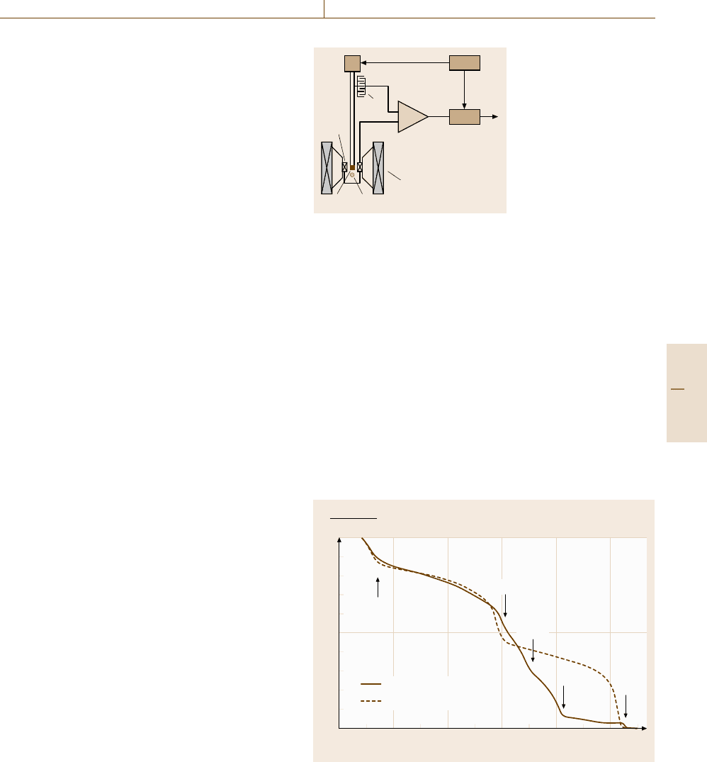
Fig. 10.2 Hysteresisgraph for hard magnetic materials. The cabinet contains two fluxmeters for H and J measure-
ment and the electromagnet power supply. The specimen and surrounding coil are placed between the poles of the
electromagnet (Permagraph C Magnet-Physik Dr. Steingroever GmbH, Köln)
netic steel or iron-cobalt alloy) and the polarizations of
permanent-magnet specimens limit the measuring range
of the method to about H < 800 kA/m in the first quad-
rant and |H|< 2400 kA/m in the second quadrant of the
hysteresis loop.
As it is impossible to saturate rare-earth perma-
nent magnets (Sm-Co, Nd-Fe-B) in an electromagnet,
it is necessary to saturate them in a pulsed magnetic
field prior to the measurement. Depending on the recoil
permeability, the polarization will be lower than the re-
manence after the specimen has been inserted into the
electromagnet and the magnetic circuit has been closed.
However, a magnetization in the electromagnet allows
full remanence to be achieved again.
Measuring Coils. Two types of measuring coils are
used: the J-compensated surrounding coil and the pole-
coil measuring system.
The J-compensated surrounding coil (Fig. 10.1)is
suitable for all kinds of permanent-magnet materials.
For the measurement it is placed around the specimen.
It consists of the following windings.
One winding with area-turns of N
1
A
1
encloses the
inner hole of the coil that accepts the specimen during
the measurement. This senses the magnetic flux pene-
trating the magnet specimen,
Φ
M
= B
M
N
1
A
M
, (10.1)
where B
M
is the flux density and A
M
is the cross-
sectional area of the magnet specimen. If the coil is not
completely filled by the specimen, the air flux between
the specimen and the winding,
Φ
A
1
=μ
0
HN
1
(A
1
− A
M
) , (10.2)
is also detected, where H is the field strength in air next
to the specimen.
A second coil with area-turns N
2
A
2
also surrounds
the specimen but does not enclose it. This senses only
the air flux,
Φ
A
2
=μ
0
HN
2
A
2
. (10.3)
Magnet specimen
N
1
A
1
N
2
A
2
Fig. 10.1
Area-turns of
a J-compensated
surrounding coil
Part C 10.2
Magnetic Properties 10.2 Soft and Hard Magnetic Materials: Measurement Techniques 551
–900 –800 –700 –600 –500 –400 –300 –200 –100
–1–2–3–4–5–6–7–8–9–10–11
0
H (kA/m)
H (kOe)
(a)
(b)
(c)
1.4
1.2
1
0.8
0.6
0.4
0.2
0
J(T); B(T)
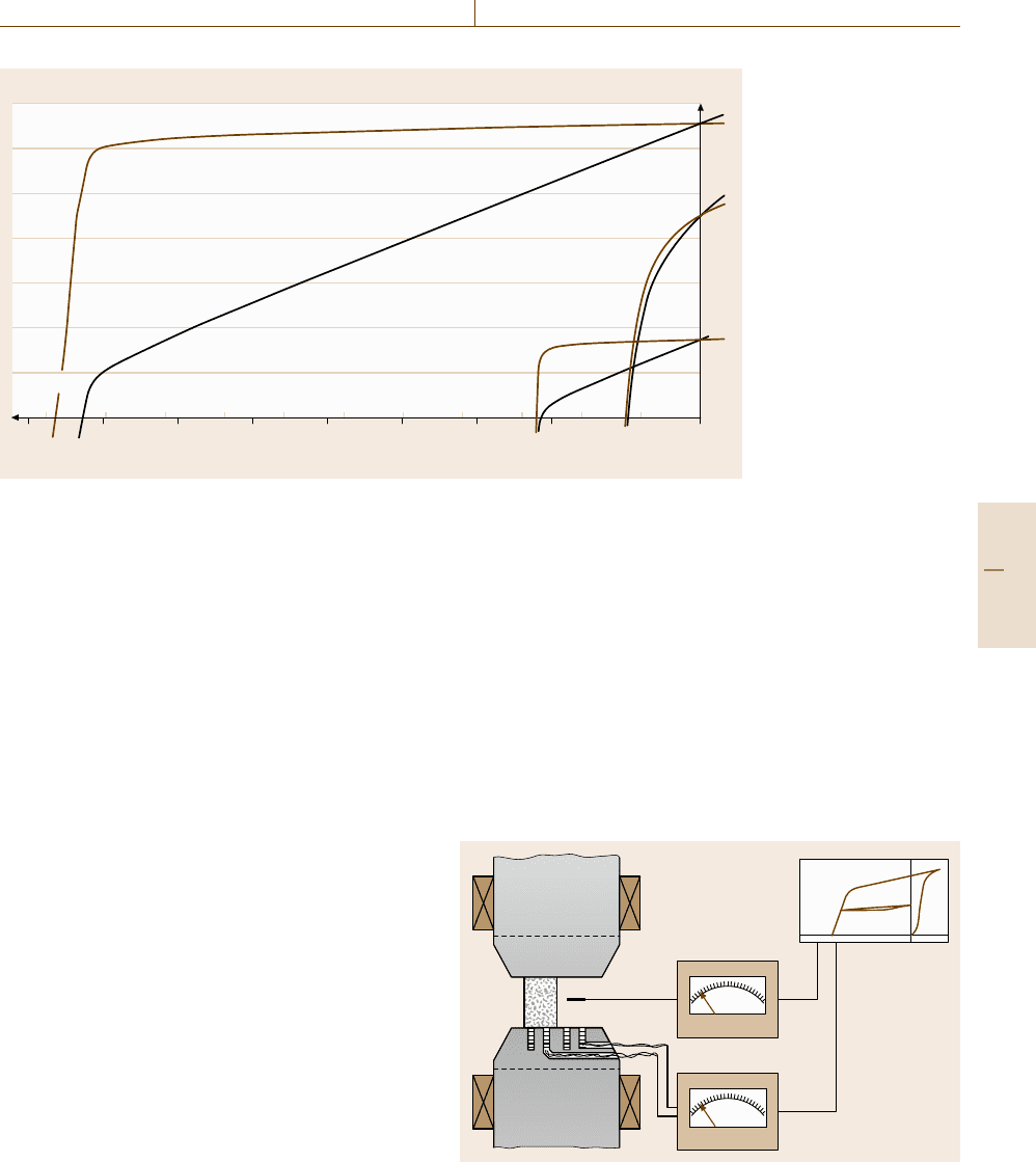
Fig. 10.3 Sur-
rounding coil
measurements
on (a) NdFeB
320/86, (b) hard
ferrite 24/23
and (c) AlNiCo
38/10 perma-
nent magnets
The area-turns of the two coils are adjusted to be equal
N
1
A
1
= N
2
A
2
. (10.4)
Both coils are connected in series opposition to
a fluxmeter integrator. If the inner of the first coil is par-
tially filled by a specimen, the magnetic flux measured
is
Φ =Φ
M
+Φ
A
1
−Φ
A
2
=(B
M
−μ
0
H)N
1
A
M
= JN
1
A
M
, (10.5)
where J is the polarization of the specimen, which is
connected to the magnetization M by J =μ
0
M.Inthe
absence of a specimen the resulting flux Φ is zero.
Usually the surrounding coil system contains a third
coil that senses the magnetic field strength H.Itiscon-
nected to a second fluxmeter integrator. In this way the
J(H) hysteresis loop can be measured directly using
one combined-coil system that can be made 1 mm thin.
The B(H) hysteresis loop can be derived from the J(H)
loop. Figure 10.3 shows the demagnetization curves of
different permanent-magnet materials measured using
surrounding coils.
Instead of the field measuring coil a Hall probe can
also be placed next to the specimen to sense H. This re-
quires additional space for the probe and an additional
measuring instrument. Because of the linearity error and
the temperature dependence of the sensitivity of a Hall
sensor, suitable corrections are necessary. Additional er-
rors can arise from the facts that the Hall probe always
has to be aligned truly perpendicular to the magnetic-
field direction and that it is, due to the small active area,
more sensitive to local field-strength variations.
The second coil system that is used in hysteresis-
graphs is the pole-coil measuring system [10.4]. It is
used mainly for hard ferrite magnets. The pole-coil sys-
tem consists of two coils that are embedded into one
pole of the electromagnet (Fig. 10.4). One coil is com-
pletely covered by the specimen. The other coil remains
free.
The first coil senses the flux density B at the surface
of the specimen. The second coil measures the magnetic
field strength H. Both coils are connected in series op-
position. In this way the polarization, J = B −μ
0
H,is
obtained directly. This compensation also cancels out
the residual field of the poles before the specimen is
inserted.
2
H
J
H
J
2
4
1
3
Fig. 10.4 Hysteresis measurement with pole coils (1 – magnet spec-
imen, 2 – electromagnet poles, 3 – pole coils, 4 – field-strength
sensor)
Part C 10.2
552 Part C Materials Properties Measurement
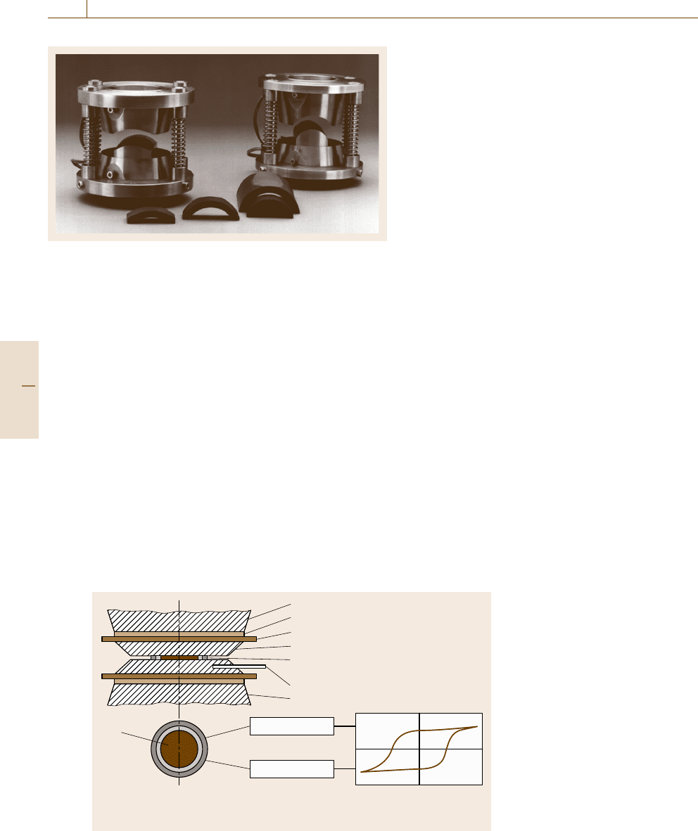
Fig. 10.5 Segment poles with pole coils
The surrounding coil measures the whole magnetic
flux penetrating the specimen. The pole-coil system
only senses the flux in a small area (typically with
a diameter of 3–6 mm) on the surface. Therefore it is
suitable for the detection of nonhomogeneities in differ-
ent regions. Especially for anisotropic ferrite magnets
it is usual to carry out measurements on both sides of
a magnet to quantify differences caused by the produc-
tion process.
Pole-coil systems are also made arc-shaped for mea-
surements on segment magnets for motor applications.
They must be machined to match the radii of the
segments exactly. Both the upper and the lower pole
contain a pair of pole coils.
Measurements at Elevated Temperatures. For meas-
urements at temperatures up to 200
◦
C pole caps with
built-in heating (Fig. 10.6) can be used. A hole in the
pole cap accepts a thermocouple for temperature meas-
Electromagnet (cold)
Thermal insulation
Heating plate
Pole face (warm)
Thermocouple
Electromagnet (cold)
Test specimen and compensated
surrounding coil for J and H
Test
specimen
Compensated
surrounding coil
for J and H
J integrator
Y
X
H integrator
Computer and/or plotter
H
J=B–µ
0
H
Fig. 10.6 Heating poles for measure-
ments at elevated temperatures
urement and control. Prior to the measurement the
specimen must remain between the poles for a sufficient
time to reach the desired temperature. The surrounding
coil needs to be temperature-proof. Hysteresis meas-
urement is carried out in the same way as at room
temperature.
Measurements on Powders. Powder samples can be
measured in the same way as solid magnets if the pow-
der is filled into a nonmagnetic container, for example
a brass ring that is sealed with a thin adhesive foil at the
bottom. As the measured polarization depends on the
apparent density, it may be more feasible to regard the
specific polarization. The coercivity H
cJ
however can be
measured directly.
Vibrating Sample Magnetometer (VSM)
The VSM is used to measure the magnetic mo-
ment m and the magnetic dipole moment j = μ
0
m
in the presence of a static or slowly changing ex-
ternal magnetic field [10.5]. As the measurement
is carried out in an open magnetic circuit the
demagnetization factor of the specimen must be
considered.
Most instruments use stationary pickup coils and
a vibrating specimen but arrangements with vibrating
coils and rigidly mounted specimens have also been
proposed. The drive is either carried out by an elec-
tric motor or by a transducer similar to a loudspeaker
system.
The specimen is suspended between the poles of the
electromagnet and oscillates vertically to the field direc-
tion; it must be carefully centered between the pickup
coils.
Part C 10.2
Magnetic Properties 10.2 Soft and Hard Magnetic Materials: Measurement Techniques 553
In the pickup coils a signal at the vibration fre-
quency is induced. This signal is proportional to the
magnetic dipole moment of the specimen but also to
vibration amplitude and frequency. The coil design en-
sures that it is independent of variations in the field
generated by the electromagnet.
The amplitude and frequency can be measured sep-
arately, for example using
•
a capacitor with one set of fixed plates and one set
of movable plates (Fig. 10.7),
•
a pickup coil and a permanent magnet,
•
an electrooptical sensing system.
The signals are fed to a differential amplifier, so
that changes of oscillation amplitude and frequency
can be compensated. A synchronous detector (lock-
in amplifier) followed by a low-pass filter produces
a direct-current (DC) output signal that only depends
on the magnetic moment.
For the generation of the outer magnetic field
a strong electromagnet is required; the field direction is
horizontal. Water-cooled magnets are mostly used but
superconducting magnets are also common. The power
required is even higher than for a hysteresisgraph as
the volume between the pole caps is quite large. The
specimen rod must be able to oscillate, and sufficient
space for a pickup coil system is required between the
specimen holder and the pole caps.
Usually a distance that is sufficient for an optional
oven or a cryostat to heat or cool the specimen is chosen.
Ovens, LN
2
or helium cryostats that are shaped to fit
between electromagnet poles are available. Care must
be taken to avoid errors due to magnetic components or
electrical supply lines. In this way the determination of
Curie temperatures and the observation of other phase
transitions become possible.
Figure 10.8 shows measurements on nanocrystalline
specimens. Measurement below room temperature was
carried out using an LN
2
cryostat. Above room tem-
perature a tubular oven was used; it had a water-cooled
outer wall to avoid heating of the pickup coils and elec-
tromagnet poles. The oven can be evacuated or filled by
an inert gas to avoid specimen oxidation.
For practical purposes and to separate the mechan-
ical system from building oscillations it is usually
mounted onto the electromagnet. This offers a stable
base due to its large mass. For high sensitivity the trans-
fer of oscillations from the drive to the pickup coils
through the electromagnet should be avoided; a me-
chanical resonator can achieve this. In this case the drive
frequency must be matched to the resonant frequency.
2
1
5
4
3
6
9
8
7
Fig. 10.7 Vibrating-
sample magnetometer:
1 – oscillator, 2 – trans-
ducer, 3 – capacitor for
frequency and amplitude
measurement, 4 – dif-
ferential amplifier, 5 –
synchronous detector, 6
– pickup coils, 7 – spec-
imen, 8 – H field sensor,
e.g. Hall probe, 9 – elec-
tromagnet poles and coils
(frame not shown)
A VSM is mostly used for measurements on mag-
netically hard or semi-hard materials. Specimen forms
include small bulk samples, powders, melt-spun ribbons
and thin films. The VSM can also be used for meas-
urements on soft magnetic materials. In this case the
electromagnet can be replaced by a Helmholtz-coil sys-
tem.
VSMs are very sensitive instruments. Commercial
systems offer measuring capabilities down to approx-
imately 10
−9
Am
2
. A system that used a SQUID
sensor instead of pickup coils achieved a resolution of
10
−12
Am
2
[10.6].
Closely related to the VSM is the alternating gra-
dient field magnetometer (AGM). As it is typically
M (T)
M (100 K)
1
0.5
0
0 200 400 600 800 1000
T (K)
Nd
2
Fe
14
B
Nd
3.8
Fe
73.3
V
3.9
Si
1
B
18
T
s
Nd
6
Fe
84
Nb
3
Si
1
B
6
Fe
23
B
6
Fe
3
B
α-Fe
Fig. 10.8 VSM measurement of the temperature dependence of
the magnetization M of nanocrystalline melt-spun samples. The
curve shows the spin-reorientation temperature T
s
of Nd
2
Fe
14
Band
the Curie temperatures of the comprised phases (heating curves,
dT/dt =45 K/min)
Part C 10.2
554 Part C Materials Properties Measurement
1
2
3
4
5
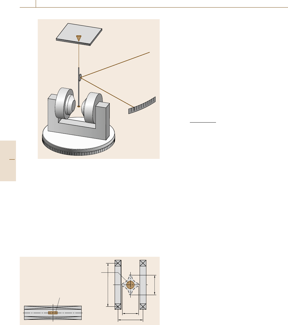
Fig. 10.9 Torque magnetometer: 1 – torsion wire, 2 – light
beam, 3 – specimen rod with mirror attached, 4 – specimen,
5 – electromagnet on rotating base
used for measurements on thin films, it is discussed in
Sect. 10.4.
Torque Magnetometer
If the magnetization energy of a freely rotating speci-
men depends on direction, the specimen aligns with its
axis of easy magnetization parallel to a magnetic field.
The axis of easy magnetization is determined by the
magnetocrystalline anisotropy energy E
a
if the speci-
men has rotational symmetry.
Magnet
Magnet
2r
r
0.6r
0.93r
a) b)
Fig. 10.10a,b Moment-measuring coils: solenoid (a) and Helmholtz
coil. (b) The dashed line in the Helmholtz coil marks the cross
section of the measuring space for 1% accuracy
If the magnetic field is rotated out of the preferred
direction by an angle α, the vector of polarization J
s
will
point in the direction of H, if the field strength is suf-
ficiently large to saturate the specimen. If H is smaller,
the direction of J
s
is rotated only by an angle ϕ<α.
For a material showing uniaxial anisotropy, the
anisotropy energy is assumed to be
E
a
= K
1
sin
2
ϕ, (10.6)
where K
1
is the uniaxial anisotropy constant. The mag-
netizing energy is
E
H
= HJ
S
cos(α −ϕ) , (10.7)
which leads to the torque
L =−
d(E
a
+E
H
)
dϕ
=−K
1
sin 2ϕ −HJ
S
sin(α −ϕ) .
(10.8)
Therefore the determination of anisotropy constants re-
quires high field strengths or suitable extrapolation.
A broad discussion of the anisotropy energy for differ-
ent crystal symmetries can be found in [10.7, Chap. 5].
The specimen is attached to a rod that is suspended
between torsion wires, and is located between the poles
of an electromagnet. The electromagnet is mounted to
a base plate that can be rotated by 360
◦
. The rotation
angle can be measured and recorded.
The excitation of the specimen is measured by the
deflection of a light beam from a mirror that is attached
to the specimen rod.
Automated systems use an electrodynamic compen-
sation of the torsion, which is measured by an optical
system consisting of a mirror attached to the speci-
men rod, a light beam and photosensors to detect the
excitation. The excitation is compensated by an electro-
magnetic system that is located outside the stray field of
the electromagnet. The current in the compensating coil
is proportional to the torque.
The main application of the torque magnetometer
is the determination of anisotropy field constants of
hard magnetic materials, including small particles and
thin films. Other applications are the determination of
texture on grain-oriented electrical sheet and strip and
the determination of the anisotropy of susceptibility of
paramagnetic materials with noncubic structure.
Moment-Measuring Coils
Helmholtz-coil configurations [10.8] are very common
for the measurement of the magnetic dipole moment of
permanent magnets. They provide a large region with
Part C 10.2
Magnetic Properties 10.2 Soft and Hard Magnetic Materials: Measurement Techniques 555
uniform sensitivity that can be easily accessed from all
sides. Long solenoids can also be used (Fig. 10.10). The
installation of the coil must be carried out with care.
No magnetic or magnetizable parts are allowed in the
vicinity of the coil as they would affect the measurement
result.
The measuring coil is connected to a fluxmeter. The
magnet specimen is placed in the center of the coil so
that the vector of polarization is aligned with the coil
axis. The fluxmeter is set to zero and the magnet is
withdrawn from the coil as long as the reading of the
fluxmeter changes. Alternatively the magnet can be ro-
tated by 180
◦
so that the vector of polarization points
in the opposite direction. If the rotation method is used,
the fluxmeter reading must be divided by 2.
The magnetic dipole moment j of the specimen is
proportional to the measured magnetic flux Φ,
j = kΦ. (10.9)
The measuring constant k can be calculated from the
dimensions and the number of turns n of the coil. For
a Helmholtz coil, k is approximately 1.4r/n, where r is
the coil radius. In practice, k is obtained by calibration.
From the dipole moment, the magnetic polariza-
tion J in the working point of a magnet with the
volume V can be calculated using
J = j/V . (10.10)
This allows the determination of the working point if
the demagnetization curve of the material is known.
For an anisotropic magnet, the polarization in the
working point is typically only 1–3% lower than the re-
manence B
r
. This fact is used in the main application of
the method: a fast and repeatable test for B
r
. This makes
it popular in industrial quality control if a measurement
of the demagnetization curve is too time-consuming or
expensive.
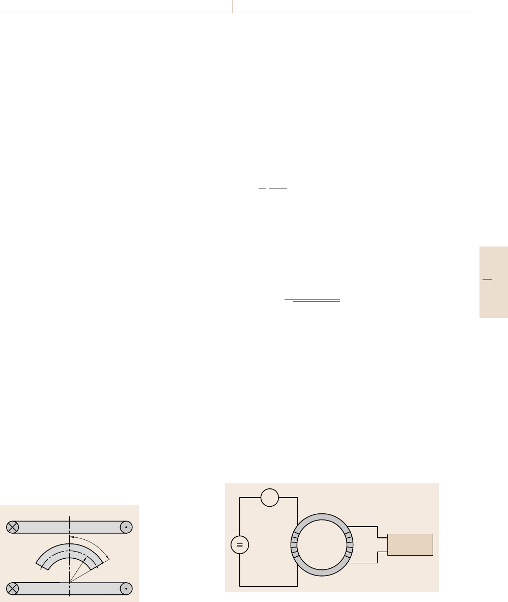
The method can also be used for radially
anisotropic, arc-shaped magnets that are common in
motor applications (Fig. 10.11). As the coil only detects
Helmholtz coil
r
ß
Fig. 10.11
Measurement
of the magnetic
dipole moment
of a radially
anisotropic seg-
ment magnet
the magnetic moment parallel to the coil axis, a correc-
tion must be applied.
The measured magnetic dipole moment is
j
=2JAr
β
0
cos β dβ. (10.11)
Here A is the cross-sectional area of the specimen. The
volume of the magnet,
V = 2Arβ, (10.12)
leads to the polarization
J =
j
V
β
sin β
. (10.13)
Another application is the determination of the
anisotropy direction of block magnets. The magnetic
dipole moment is measured in the direction of one ge-
ometrical symmetry axis ( j
x
) and in two perpendicular
directions ( j
y
, j
z
).
The angle α between the geometrical symmetry axis
and the axis of anisotropy is
α = arccos
j
x
j
2
x
+ j
2
y
+ j
2
z
. (10.14)
10.2.3 Properties of Soft Magnetic Materials
DC Hysteresisgraph – Ring Method
The basic method for the measurement of quasistatic
hysteresis loops mostly uses ring-shaped specimens
(Fig. 10.12). Other specimen shapes providing a closed
magnetic circuit with constant cross section may also be
appropriate. The specimen is equipped with a primary
winding and a secondary winding.
Usually the bipolar current source is computer-
controlled and the fluxmeter and ammeter are also
integrated into a data-acquisition system.
Fluxmeter
A
N
1
N
2
Fig. 10.12 Circuit of the ring method
Part C 10.2
556 Part C Materials Properties Measurement
The magnetizing current I is applied to the primary
winding. The magnetic field strength H is calculated
from
H =
N
1
I
l
m
, (10.15)
where N
1
is the number of turns of the primary winding.
The mean magnetic path length l
m
is usually obtained
from
l
m
=π
D +d
2
, (10.16)
where D is the outside diameter and d is the inside
diameter of the ring.
The radial variation of H must be kept small. There-
fore the ratio between the outer diameter and inner
diameter should not exceed 1.4. Thinner rings are often
impracticable, especially for fragile sintered specimens.
If this condition cannot be met for any reason, l
m
can
better be calculated with respect to the average field
strength,
l
m
=π
D −d
ln
D
d
. (10.17)
The voltage that is induced into the secondary wind-
ing must be integrated to obtain the magnetic flux Φ.
Therefore a fluxmeter is used. From the flux Φ,theflux
density B is calculated as
B =
Φ
N
2
A
. (10.18)
Here N
2
is the number of turns of the secondary wind-
ing and A is the cross-sectional area of the specimen.
For a massive ring of rectangular cross section and
height h, the area is calculated from
A =
D −d
2
·h . (10.19)
If the ring consists of stacked sheets or wound ribbons,
the area must be calculated from
A =
2m
ρπ(d + D)
, (10.20)
where m is the mass and ρ is the density of the specimen
material.
Prior to the measurement the specimen is demagne-
tized. An alternating current with decreasing amplitude
is applied to the primary winding. The frequency
and decay rate of this current can be preset. The
measurement can then be started with the initial magne-
tization curve. The hysteresis loop is either excited up
to the maximum current provided by the current source
or to a preset limit of H or B.
Often the measuring speed is controlled so that
a constant rate of change of the flux density with time,
dB/ dt, is achieved. This allows the steep parts of the
loop to be passed slowly to avoid errors due to eddy
currents. The flat parts of the curves can be passed faster
as eddy currents do not affect the magnetization. How-
ever, the instrument must also have the possibility to run
curves at constant speed, for instance in the case that
control is not possible, e.g. for a high squareness loop.
The typical time to trace a hysteresis loop is of the order
1min.
Quasistatic measurement allows one to obtain mag-
netic material properties independently of the influence
of eddy currents. In this way the hysteresis loss can be
obtained directly by integrating the area of the hystere-
sis loop
P =
B dH . (10.21)
Coercivities of soft magnetic ring specimens range from
less than 0.1A/m for ring cores made of wound ribbons
of amorphous alloys up to several 100 A/m for rings
made of solid steel or sintered material. Depending on
the ring dimensions, current and number of primary
turns, typically maximum field strengths up to approxi-
mately 10 kA/m can be achieved.
The permeability curve μ
r
(H) can be created by di-
viding the corresponding values of B and μ
0
H,which
are usually taken from the initial magnetization curve.
The highest point of the μ
r
(H) curve, the maximum
permeability μ
max
, is typically stated in measurement
reports.
Figure 10.13 shows some sample measurements
on different materials. The field-strength excitation is
5kA/m for the Fe-Si and 60 A/m for the Fe-Ni speci-
men.
WindingaRingSpecimen.In schematic drawings
such as Fig. 10.12 primary and secondary windings are
usually shown on opposite sides of the ring. This con-
figuration produces a high stray field if the permeability
decreases while approaching saturation. Therefore, both
windings are often equally distributed around the cir-
cumference if the number of turns is sufficiently large.
To avoid air flux between the ring and the secondary
winding, this winding is wound directly onto the ring.
The primary winding is wound onto the secondary
winding.
Part C 10.2
Magnetic Properties 10.2 Soft and Hard Magnetic Materials: Measurement Techniques 557
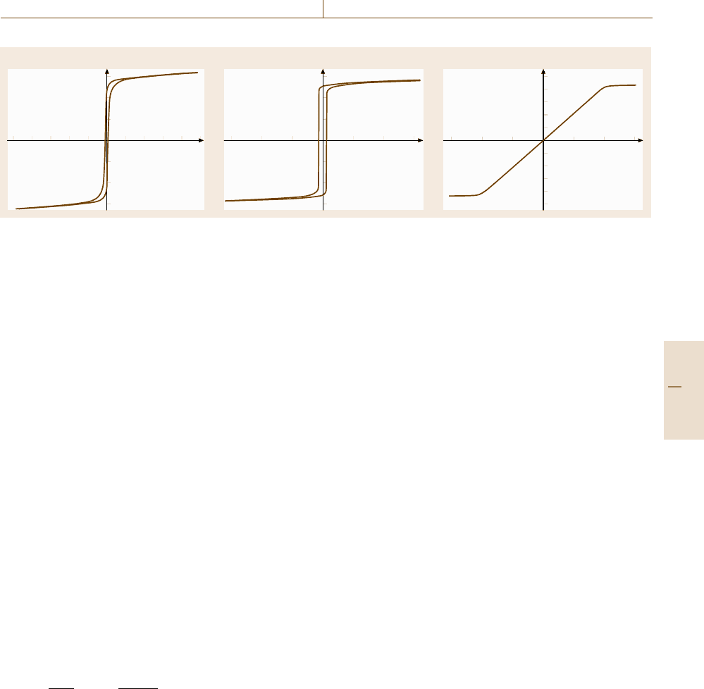
a) b) c)
B (T) B (T) B (T)
H (kA/m) H (kA/m)H (A/m)
1.5
1
0.5
1–1 –60 –40 –20 20 40 60 –1.5 –1 1
1
0.8
0.6
0.4
0.2
–0.2
–0.4
–0.6
–0.8
–1
1.5–0.5 0.5
–1
–0.5
–1.5
1.5
1
0.5
–1
–0.5
–1.5
–2–3–4–5 2 3 4 5
Fig. 10.13a–c Hysteresis loops of ring specimens measured by the DC ring method, (a) Fe-Si alloy with round (R-)hysteresis
loop, (b) Fe-Ni alloy with high squareness (Z-)loop, (c) amorphous cobalt alloy with flat (F-)loop
Each of the equally distributed windings produces
an effective circular turn with a diameter equal to the
mean diameter of the ring. In this way the primary wind-
ing produces a magnetic field in the direction of the
ring axis. This can be avoided by winding the turns in
pairs of layers that are wound alternating clockwise and
counterclockwise around the ring.
This also reduces the error arising from the effective
mutually inductive coupling between the two windings
in the axial direction. To minimize this error, the wire
of the secondary winding can also be led back along the
mean diameter of the ring.
After winding, the specimen should be checked for
short circuits between the windings and core.
Specimens for ring-core testing include wound rib-
bons of amorphous alloys and iron-nickel alloys. If the
magnetic properties can easily be altered by mechani-
cal stress, the windings cannot be applied to the cores
directly. The cores can be coated or placed in plas-
tic core boxes that are wound afterwards. Prefabricated
windings with multipole connectors are also used.
Depending on the field-strength range, the air flux
between the measuring winding and specimen must be
considered. The flux density must then be calculated
from
B =
Φ
N
2
A
−μ
0
H
A
2
− A
A
, (10.22)
where A
2
is the cross-sectional area of the secondary
winding and A is the area of the specimen.
DC Hysteresisgraph – Yoke Methods
The DC hysteresisgraph or permeameter is used for
quasistatic hysteresis measurements on soft magnetic
materials. The specimen can either be a bar with round
or rectangular cross section or a strip of flat material.
The choice of the method depends on the shape and
magnetic properties of the specimen. Yoke methods are
generally used instead of the ring method if the coerciv-
ity of the specimen material is larger than 50–100 A/m.
Maximum field strengths range from 50–200 kA/m.
The most widespread yoke configurations today
are the permeameter yokes type A and type B ac-
cording to [S-10-31] and the Fahy permeameter [10.9]
(Fig. 10.14). Many other, often similar, configurations
have been designed. A larger collection can be found
in [10.10].
For the measurement of the flux density B,acoil
that is directly wound onto the specimen can be used. In
everyday use J-compensated coils are often preferred.
They can be made sturdier and can be used for speci-
mens with various diameters and shapes.
The measurement of the field strength H can be
carried out by a Hall probe or a field-measuring coil
(search coil) next to the specimen. Due to the restricted
space, this approach is used with the type A permeame-
ter. Another way is a c-shaped potential-measuring coil,
asshowninFig.10.14b for the type B permeameter. It is
placed directly onto the specimen surface and senses the
magnetic potential difference P between its ends. The
magnetic field strength is obtained by H = P/s, where
s is the distance between the ends of the potential coil.
A straight potential-measuring coil can be used with the
Fahy permeameter.
In the type A permeameter, the specimen is sur-
rounded by the magnetizing coil. This configuration
generates relatively high field strengths. However, spec-
imen and field strength sensor are heated directly by
the power dissipation in the coil. If the field strength is
increased above approximately 50 kA/m, forced air or
even water cooling becomes necessary. The minimum
specimen length for the type A permeameter is 250 mm.
Part C 10.2