Czichos H., Saito T., Smith L.E. (Eds.) Handbook of Metrology and Testing
Подождите немного. Документ загружается.

568 Part C Materials Properties Measurement
a new instrument that is well suited for fast and reliable
measurement of the hysteresis loops of hard magnetic
materials.
10.3.1 Industrial Pulsed Field
Magnetometer
A short-pulse system (typical pulse duration 1–50 ms)
has a condenser battery as an energy source, which has
a certain size given in kJ (typical values are 10–100 kJ).
The available power determines the time constant of the
total system.
Figure 10.30 shows a block diagram of a pulsed
field magnetometer (PFM) [10.10, 31]. A pulsed field
magnetometer consists of
1. the energy source, generally a capacitor battery; the
stored energy is given by CU
2
/2. The maximum
charging voltage can be 1–30 kV. The capacitance
determines the costs of such a system, the maximum
sample size and the time constant. For a mag-
netometer that can measure the full loop, voltage
reversal on the battery must be allowed.
2. charging unit, which should generate a reproducible
and selectable charging voltage; it determines the
repeatability of the achieved field in the pulse mag-
net.
3. pulse magnet: for an existing energy, the pulse
magnet determines, via its inductivity, the pulse
duration. Additionally the volume (diameter, homo-
geneity) limits the dimensions of the experiment
inside of the magnet. Heating during a pulse may
be also a problem when high repetition rates are
desired.
Controller
Computer
C++ software
Data aquisition card
J & H integrators
Capacitor bank
Coolant
Diode
Thyristor
Pulsed magnet
Pickup
Fig. 10.30 Block diagram of a typical capacitor-driven in-
dustrial PFM
4. measuring device: this consist of the pickup system
and the measuring electronics (amplifiers, integra-
tors, PCs, data storage). A careful design of the
pickup system is very important in order to achieve
a high degree of compensation and consequently
a good sensitivity.
5. electronics: this consist either of a digital mea-
suring card or of a storage oscilloscope which is
connected to a modern data-acquisition system on
a standard PC, which allows a software-supported
operation of the PFM (charging, discharging and
the measurement with an evaluation of the resulting
loop). In order to obtain a reasonable accuracy the
analog-to-digital converters (ADCs) of the storage
oscilloscope (measuring card) should have a resolu-
tion of at least 12 bit.
High-Field Magnets
The pulse magnet has to be optimized with respect to
the available power, the heating of the magnet and the
stresses. The field homogeneity over the desired length
of the experiment should be better than 1%. In systems
where the hysteresis loop is measured, the pulse magnet
has to be optimized with respect to low damping and
also for a certain measuring task (maximum field, pulse
duration, pulse shape, sample volume).
Pickup Systems
Generally the magnetization is measured using a pickup
coil system, which has to be compensated in order
to measure the magnetization M instead of the in-
duction B. For this purpose different arrangements of
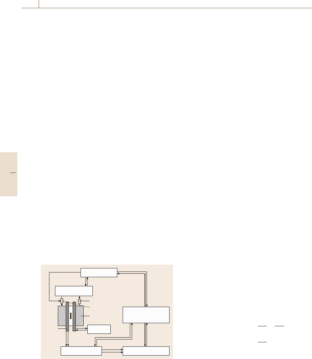
pickup coils have been developed (Fig. 10.31). It was
found that a coaxial system based on Maxwell coils is
best suited to this purpose [10.32]. The main idea of
constructing a pickup system is that the space distri-
bution of the field around the sample is first developed
into a dipole (and quadruple) contribution. These con-
tributions should be compensated in order to cancel
the effect of the external field. Therefore such systems
consist of at least two coils (Fig. 10.31c). The induced
voltages can be written as
u
1
(t) =−μ
0
N
1
K
1
R
2
1
π
dH
dt
+
dM
dt
,
u
2
(t) =−μ
0
N
2
K
2
R
2
2
π
dH
dt
; (10.45)
where u
i
, N
i
, K
i
R
i
(i = 1, 2) are the induction voltage,
number of windings, coupling factor, radius of the outer
(i = 1) and inner (i = 2) pickup coil, respectively.
Part C 10.3
Magnetic Properties 10.3 Magnetic Characterization in a Pulsed Field Magnetometer (PFM) 569
Dipole compensation is fulfilled when R
2
1
N
1
=
R
2
2
N
2
is valid. The coupling factor with respect to the
field H is the same for both coils, but not with respect to
the sample. It is assumed that for the outer coil the volt-
age due to the magnetization can be neglected (in reality
there exists a small induction voltage due to M which
only reduces the calibration factor). Subtracting now the
signal of the two antiparallel-wound coils causes a can-
celling of the effect of the field, which yields the dipole
compensation. Also higher multipoles can be compen-
sated, which leads to a more complex pickup system
for which more space is necessary. Therefore for pulsed
field systems usually only the dipole compensation is
used.
For some applications the pickup system should be
cooled in order to hold a stable temperature, which
is especially important for a room-temperature system
with a high repetition rate. The details of such a pickup
system as well as electronic balancing are described
in [10.33].
For an industrial system a reasonable sample size
is important; typical values are samples up to 30 mm
in diameter and 10 mm in length within a ±1% pickup
homogeneity range. For magnetic measurements exact
positioning (reproducibility better than 0.1 mm) in the
PFM is necessary.
10.3.2 Errors in a PFM
The Demagnetizing Factor
In a magnetically open circuit the correction for the de-
magnetizing factor N is a very important step to get the
true hysteresis loop as a function of the internal field
H
int
. For ellipsoids and spheres the demagnetizing field
H
d
is simply written
H
int
= H
ext
−NM ,
H
d
= NM . (10.46)
The demagnetizing factor N is just a number 0 < N < 1
for a sphere (N =1/3) or an ellipsoid. In all other cases
the demagnetizing field H
d
is no longer constant.
Important points such as the remanence and the
working point, but also the energy product (BH)
max
,
depend strongly on N. Unfortunately in industry more
complex shapes, such as cylinders, cylinders with holes
and even arc segments, are used. In this case N can be-
come a tensor according to the symmetry of the sample.
For complex shapes a finite-element package has to be
used in order to calculate the stray field.
In order to investigate the effect of N for simple
shapes in Fig. 10.32 the demagnetizing curves in the
a)
b)
c)
NN
N
N
2
N
1
r
1
r
2
r
r
N/2 N/2
Fig. 10.31a–c Scheme of
a coaxial pickup sys-
tem for measuring the
magnetization
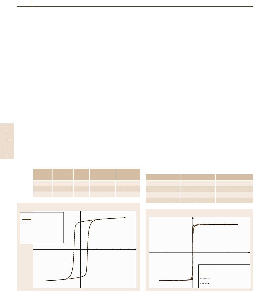
second quadrant for an anisotropic ferrite HF 24/16 are
drawn. The two samples were from the same batch, one
was a cylinder and one a sphere. The shape of the loops
agrees very well. This means that in this special case the
use of a constant number for N even for the cylinder is
sufficient for the correction.
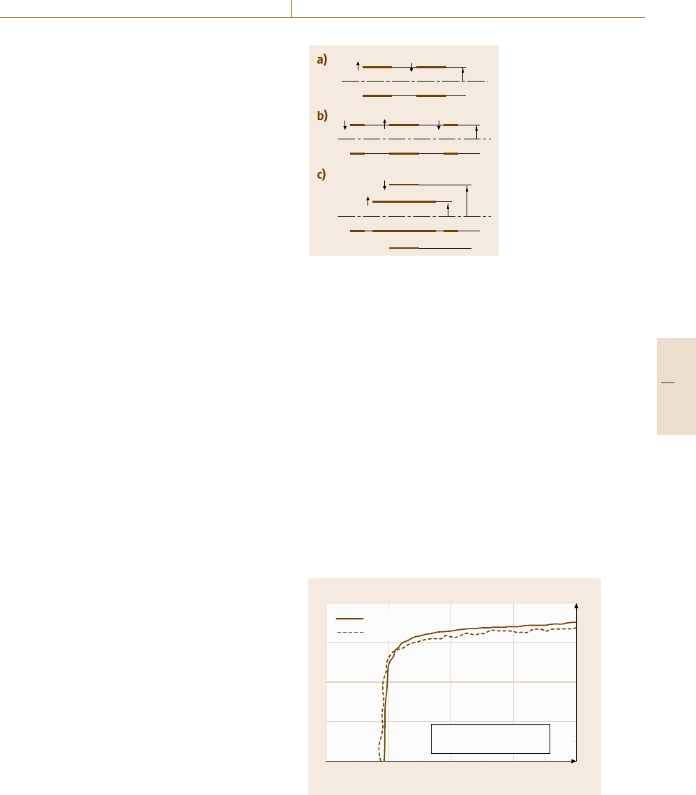
Figure 10.33 shows the hysteresis loop as meas-
ured on a cylindrical sample with a hole (outer diameter
19 mm, hole: 3.17 mm; h = 2 mm) of plastic-bonded
Nd-Fe-B-type material. Assuming N = 0.45 gives a re-
manence of 0.666 T, whereas assuming N = 0.55 deliv-
ers a remanence of 0.682 T. The static value measured
with an electromagnet was 0.682 T. This demonstrates
the problem of such an unknown demagnetizing factor.
It is impossible to say what the correct value is really.
Finally it should be mentioned that the problem dis-
cussed here of an unknown demagnetizing factor is not
only a problem for the PFM; this is a general problem
Cylinder
Sphere
BaFe cylinder + sphere
HF 24/16 part 9B + 10B
–0.4 –0.3 –0.2 –0.1 0
0.4
0.3
0.2
0.1
0
H
int
(MA/m)
µ
0
M (T)
Fig. 10.32 Demagnetizing curve as obtained for a spherical
and a cylindrical anisotropic Ba-ferrite (HF 24/16)
Part C 10.3
570 Part C Materials Properties Measurement
–3
–1
–0.5
0.5
1
–2 2 3 4
µ
0
M (T)
H
in
(MA/m)
Bonded ND-Fe-B ring with hole
SDF = 0.45
B
r
= 0.666T;
I
H
C
= 751 kA/m
Fig. 10.33 Hysteresis loop of a cylindrical sample with
a hole of plastic-bonded Nd-Fe-B-type material
for all magnetometers using a magnetically open circuit,
such as e.g. in a VSM or also in a SQUID.
Transient-Field Errors
The application of transient fields causes errors, which
have to be considered. Two possible errors may arise in
pulsed field measurements due to the field sweep rate
dH/dt
a) Eddy current errors,
b) Magnetic viscosity effects.
Eddy Currents and Their Solution [10.34]
A time-dependent external magnetic field in a metallic
conducting sample causes, according to Maxwell equa-
tions, currents (eddy currents), which create a dynamic
magnetic moment that is antiparallel to the external
field, as is demonstrated in Fig. 10.34. The time behav-
ior is exponential: I(t) = I
0eddy
exp(−r/M)t, where M
is a dynamic mutual inductance and r is also a differen-
tial resistance due to the path of the eddy currents.
It can be shown [10.34] by solving the Maxwell
equations for an electrical conducting material (without
considering the permeability) that the dynamic magne-
B
m
B =B(x, t)
j
eddy
= σE
σ
Fig. 10.34 The
principle of
eddy currents
in a metallic
sample
tization due to eddy currents can be written as
M =curl j =−σ
∂
∂t
(curlA) =σ
∂ B
∂t
=
μ
ρ
∂ H
∂t
.
(10.47)
This means that plotting the magnetization m due to
eddy currents versus dH/dt of a conducting sample de-
livers a linear relation where the slope is proportional
to σ (specific electrical conductivity) which is equal
to 1/ρ (specific electrical resistivity), as is also found
experimentally.
The maximum eddy-current density (J
max
=
J(r
sample
, z = 0)) of all samples with different pulse du-
ration and their magnetic moment m
FEMM
, m
FEMM
can
also be calculated using a finite element package such
as FEMM by Meeker [10.35] (2-D finite-element soft-
ware). For samples that are not large and frequencies
that are not high a linear relation between the eddy-
current density and the radius r holds, which gives
a rather simple solutions for calculating the dynamic
eddy-current magnetization, as follows.
The magnetization for a cylinder is
M =
j
max
r
s
4
. (10.48)
Hence, the magnetization is independent of the height
of the cylinder.
A similar calculation delivers the magnetization for
a sphere
M =
j
max
r
s
5
. (10.49)
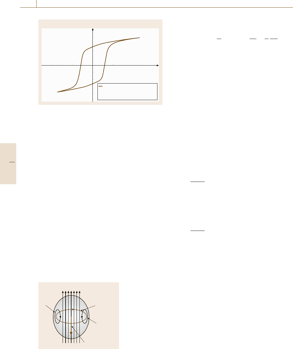
To prove the assumption that the magnetization due to
the eddy-current density increases linear with the ra-
dius but stays constant with the height of the sample,
several cylindrical and spherical samples of Cu were
studied [10.34]. It was demonstrated that the measured
maximum magnetization can be fitted with a function
f =Cr
2
, where r is the radius of the sample, which
gives, as theoretically expected, a quadratic dependence
asshowninFig.10.35.
On the experimental side, in agreement with the
formulas above, the eddy currents were found to be
independent of the height of the sample [10.36].
Conducting, Magnetic Samples –
f /2f Method [10.37,38]
In a magnetic material the eddy currents are determined
by the electrical conductivity σ but also by the perme-
Part C 10.3
Magnetic Properties 10.3 Magnetic Characterization in a Pulsed Field Magnetometer (PFM) 571
ability μ, where the latter is also a nonlinear function of
the external field. In this case the eddy-current problem
cannot be solved analytically. Here, numerical meth-
ods are the only possible way. However in some cases
simplifications are possible. In order to correct the hys-
teresis loop of a hard magnetic material as measured
in a PFM for the eddy-current error a special method
was developed. The hysteresis loop of each sample is
measured with two different pulse durations, f and 2 f ,
which generate the same J signal with respect to the
applied field but with the addition of different dynamic
magnetizations due to eddy-current distributions. The
eddy currents are related to the frequency; the eddy-
current magnetization is approximately proportional to
dH/dt, as was shown already. By processing the two
measurements it is possible to remove the error due to
eddy currents, producing the direct equivalent of a static
hysteresis plot; this approach is known as the f/2 f
method [10.37, 38]. This method is based on the fol-
lowing equations
H
m
= H
ext
−H
eddy
+H
d
, (10.50)
where H
ext
is the external field applied by the pulse,
H
eddy
is the dynamic field caused by the eddy currents,
and H
d
is the demagnetizing field.
The polarization J appearing in a pulse-field exper-
iment consists of two components, the true polarization
J
DC
(H
DC
) as measured as a function of a DC field
H
DC
and the apparent polarization due to eddy cur-
rents J
eddy
. Now performing two experiments, one with
a short pulse (described by “s”) and one with a long
pulse (described by “l”) one gets a set of field data and
polarization data
H
ext,s
+
J
eddy,s
μ
0
= H
ext,l
+
J
eddy,l
μ
0
. (10.51)
Based on these equations a mathematical procedure was
developed which delivers the so-called f/2 f correction.
This method can be applied under the general assump-
tion of a sufficiently small eddy-current error, which
means less than 20%. The validity and the limits of the
f/2 f method were investigated and proofed by a three-
dimensional (3-D) finite-element calculation [10.39].
Therefore, this so-called f/2 f method seems to be
a good way to correct eddy-current errors in the meas-
ured hysteresis loop.
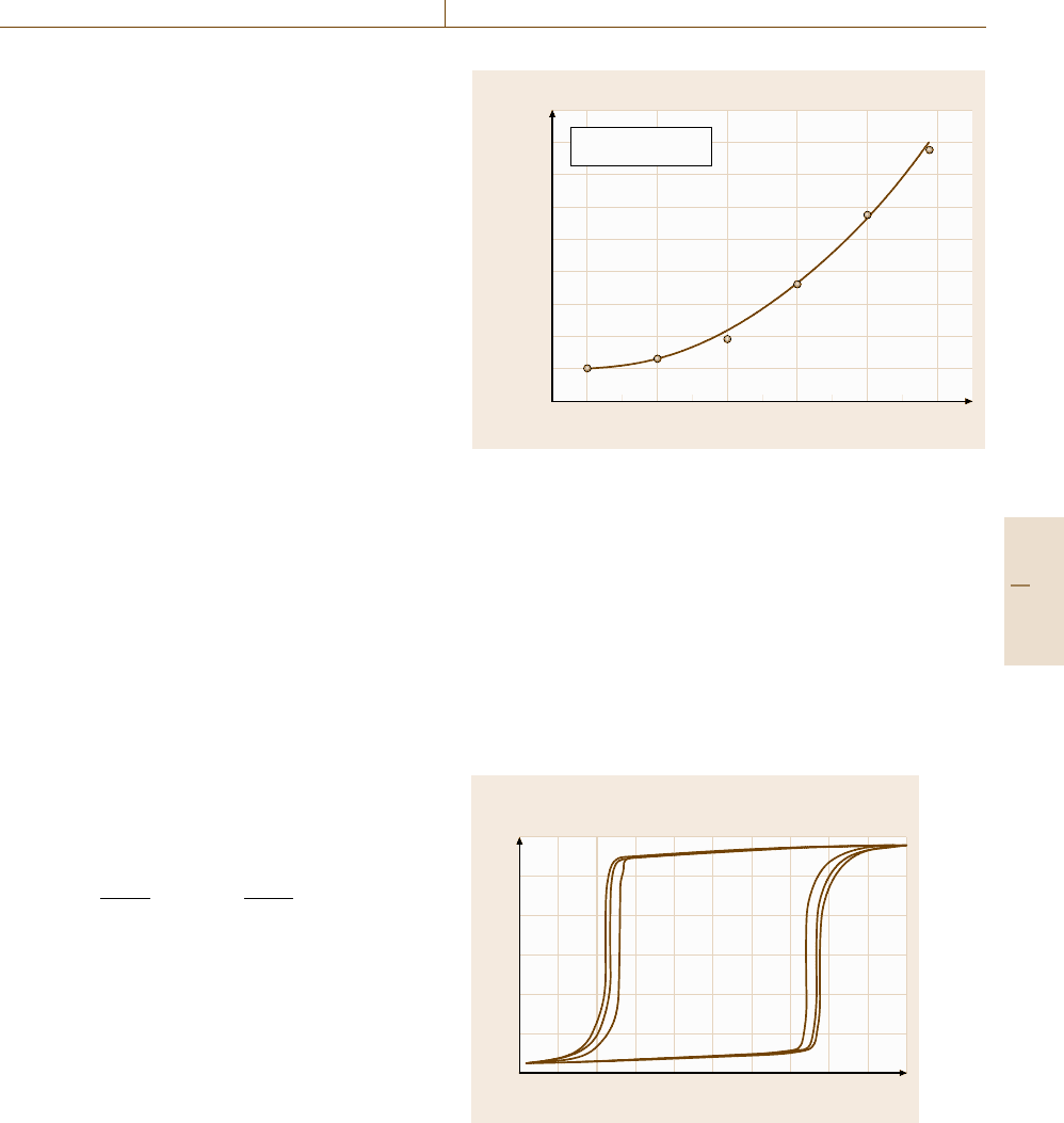
Application of the f /2f Correction to a Magnet
To test the f/2 f correction a large cylindrical commer-
cial Nd-Fe-B magnet from VAC (Vacodym 510, Charge
800 000
700 000
600 000
500 000
400 000
300 000
200 000
100 000100 000
–100 000
0
0246810
d (mm)
M
max
(A/m)
Cu, cylinder, h =8mm
8 mF, 9.1 ms
Fig. 10.35 Dependence of the maximum eddy-current magnetiza-
tion on the radius
210105) was measured (Fig. 10.36). This cylinder had
a diameter of d = 20 mm, and a height of 6.9mm.
The static data measured by VAC were: remanence
B
R
=1.296 T, and coercivity
I
H
C
=1255 kA/m.
The f/2 f -corrected coercivity value was found to
be 1275 kA/m, which is 2% too high. The measured
remanence value of 1.25 T is about 2% too low. This
is experimental proof of the validity of this f/2 f
correction.
Vacodym 510 sintered NdFeB; long (f), short (2f) and corrected
J (T)
1.5
0.5
–0.5
–1
–1.5
–2000 –1000 0 1000 2000
1
0
H (kA/m)
Fig. 10.36 Room-temperature hysteresis loop as obtained
on a large (20 mm diameter) sintered Vacodym 510 mag-
net. One loop was measured with a long pulse (time
duration of 57 ms) and one with a short pulse (time dura-
tion of 40 ms) (outer loop). The inner lying loop represents
the corrected hysteresis
Part C 10.3
572 Part C Materials Properties Measurement
Magnetic Viscosity
The magnetic viscosity can influence the shape of
ainaPFM-measured hysteresis loop. This leads
especially to higher coercivity values measured in
a transient field. The general questions are: how large
is this error, when is this error not negligible, what
is the origin of this error, and can this error be
corrected?
The effect of magnetic viscosity has been well
known for many years and has been investigated for
many hard magnetic materials [10.40, 41]. It has also
been shown that the magnetic viscosity coefficient S
v
can be used to determine the activation volume, an
important parameter for the understanding of the coer-
civity mechanism [10.42]. The viscosity coefficient is
usually determined by static field measurement. One
measures the loop M(H) and stops in the second
quadrant with this measurement at a certain field H.
There under the condition H =const. the time depen-
dence of M is measured, from which the magnetic
relaxation coefficient S = dM/ dlnt can be determined.
For calculating S
v
one needs also the irreversible sus-
ceptibility χ
irr
. One has to consider that the typical
field sweep rate in pulsed field experiments dH/dt
is approximately 1000 T/s, which is 10
6
orders of
magnitude larger than the field sweep rate dH/dt
that can usually be achieved in VSMsusinganelec-
tromagnet or a superconducting coil. Generally, the
viscosity coefficient (S
v
) determined from static field
measurements (denoted by S
vJ
) is much smaller than
that obtained from PFM measurements (denoted as
S
vp
). However, it may be of great importance that the
time windows in these two experiments are completely
different.
Experimental Method to Determine Viscosity
In order to obtain the coercive field of the specimen un-
der fields with different sweep rates, hysteresis loops
of the samples are recorded at a fixed temperature by
using a pulse field magnetometer (PFM) applying a suf-
ficiently high maximum field. The sweep rate dH/dt
can be changed either by varying the capacitance of
the condenser battery or by changing the amplitude of
the field or both; with this method field sweep ranges
from about 0.5upto20GAm
−1
s
−1
and even higher are
possible. The dependence of the coercivity on the field
sweep rate dH/dt can be used to estimate the viscosity
S
v
(10.52)
S
νp
=
H
C
1
−H
C
2
ln
(
dH
1
/dt
)
/
(
dH
2
/dt
)
.
(10.52)
This method and its limitation were recently demon-
strated on the model material SmCo
5−x
Cu
x
and related
compounds [10.43].
The Magnetic Viscosity
in SmCo
5−x
Cu
x
Alloys [10.43]
SmCo
5
is nowadays a standard permanent-magnet ma-
terial. However, substituting Co by Cu causes a change
of the coercivity mechanism from nucleation to pin-
ning. Additionally it was found that in Sm(Co, Cu)
5
a large magnetic-viscosity effect appears. Therefore this
is also a model material in order to investigate viscos-
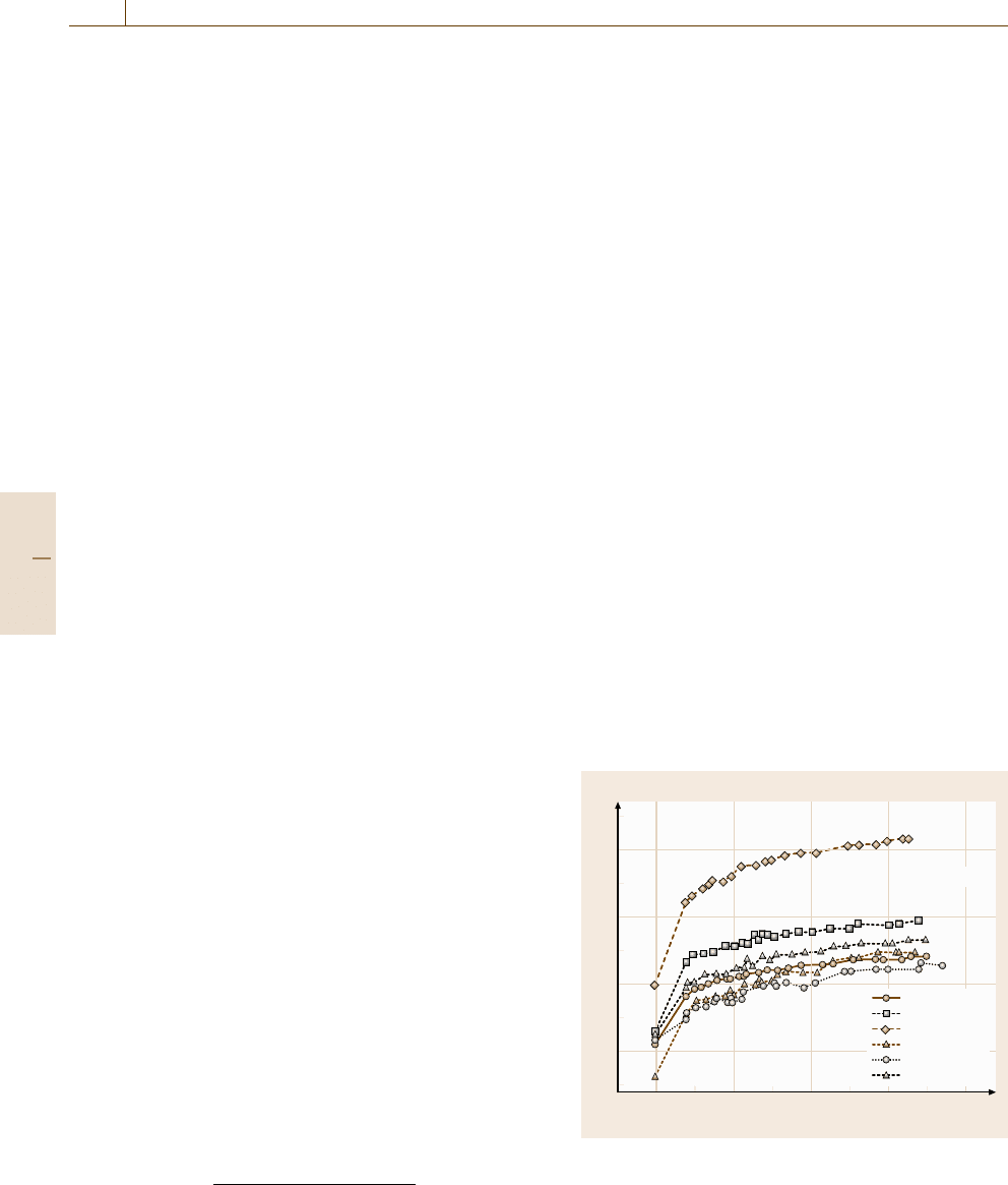
ity effects in a PFM.InFig.10.37 the coercive field
as a function of dH/ dt, as measured in as-cast and
annealed SmCo
5−x
Cu
x
magnets, is presented. The co-
ercivity increases with dH/dt, providing evidence for
the existence of a strong magnetic aftereffect.
Conclusion
a) Eddy-current errors. The application of a transient
field causes eddy currents in metallic samples which
lead to a dynamic magnetization M
eddy
that is propor-
tional to dH/dt [10.34]; the proportionality factor is
the specific electrical conductivity. Additionally, M
eddy
scales with R
2
(R is the radius of a rotational sym-
metrical sample), which means that the error increases
quadratically with increasing sample diameter [10.34].
Fortunately most of the metallic permanent magnets are
sintered materials where the specific resistivity (typi-
cally 2 × 10
−4
Ω m) is generally a factor 50–100 higher
1.6
1.2
0.8
0.4
0 5 10 15 20
H
c
(MA/m)
dH/dt ((GA/m)/s)
SmCo
5–x
Cu
x
Cu
1.5
annealed
Cu
2.0
annealed
Cu
2.5
annealed
Cu
3.0
annealed
Cu
2.0
as-cast
Cu
2.5
as-cast
Fig. 10.37 Coercive field as a function of the sweep rate
dH/dt measured in as-cast and annealed SmCo
5−x
Cu
x
al-
loys
Part C 10.3

Magnetic Properties 10.3 Magnetic Characterization in a Pulsed Field Magnetometer (PFM) 573
that of Cu. Therefore the error in magnetization meas-
urements due to eddy currents is rather small. These
considerations have led to the development of eddy-
current correction for hysteresis loops measured in
pulsed fields, which is called the f/2 f method. In this
case one measures the loop with two different pulse
durations and calculates the corrected loop point by
point, applying an extrapolation procedure [10.37, 38].
It was shown by finite-element calculations that for
eddy-current errors that were not too large (less than
20%) the corrected loop agrees with the true loop within
2%. This means that the effect of eddy currents is under-
stood and can be corrected in most cases [10.39].
b) Magnetic viscosity effects. When the hysteresis loop
of hard magnetic materials is measured in transient
fields the so-called magnetic viscosity causes a differ-
ence between the measured loop and the true loop.
The magnetic viscosity is also observed in nonconduct-
ing materials (e.g., ferrites), therefore it is not due to
eddy currents. It has to be mentioned that the time
constant of the exponential decay of of eddy currents
(in metallic samples) is of the order of typical val-
ues of microseconds, whereas that of the logarithmic
decay of the viscosity lies between milliseconds and
seconds. Additionally eddy currents depend on the ge-
ometry of the sample whereas this is not the case for the
viscosity.
10.3.3 Calibration [10.1]
Field Calibration
The field is calibrated using a small pickup coil whose
effective winding area is known from an NMR cali-
bration. The induced voltage u(t) is then fitted using
(10.53), in order to determine the field calibration
factor k, the damping factor and the pulse duration (in-
cluding the effect of the damping)
H = H
0
exp(−at) sin ωt ,
u
i
(t) =−NA
dB
dt
=−NAμ
0
H
0
d
dt
exp(−at) sin ωt
. (10.53)
Table 10.3 Summary of calibration results
Sample Shape μ
0
H
max
(T) μ
0
M μ
0
M
literature
Error μ
0
M (T)
t = 57 ms (T) (T) (%) t = 40 ms
Fe
3
O
4
Sphere 2r = 5.5mm 1.5 0.5787 ±0.001 0.569 [10] +1.6 0.5782
Ni Cylinder D = 4;h =8mm 1.5 0.6259 ±0.0008 0.610 [11] +2.6 0.6322
Fe Cylinder D = 4;h =8mm 4.5 2.1525 ±0.0051 2.138 [12] +1.4 2.1826
The damping factor a determined in this way can be
compared with the value given by a PFM circuit us-
ing a ≈ R/2L (where R is the resistivity of the pulse
magnet, and L is the inductivity of the pulse magnet).
The calibration factor k is also determined as
a function of the gain (integrator gain and the gain of
preamplifier). The calibration factor k gives a relation
between the induced voltage and the field at the search
coil. At the same time the integrated voltage (using dif-
ferent gain factors) of the H-measuring coil (which is
located at the pickup rod) on the magnetometer system
is recorded.
It was shown that the calibration factor k was also
determined as a function of the gain using an analogue
integrator [10.1]. The scattering of the k factor was be-
low ±1%. This indicates that the linearity of the gain
is better than 1%. Using such a procedure, an absolute
field calibration of better than 1% is achieved, including
the time constants (gain) of the integrator.
Magnetization Calibration
The magnetization is calibrated using well-known ma-
terials such as Fe and Ni (in which the eddy-current
error causes an uncertainty) or preferably a nonconduct-
ingsamplesuchasFe
3
O
4
or a soft magnetic ferrite,
such as 3C30 (Philips). All calibration measurements
are performed at room temperature. The results of
the magnetization calibration measurements are sum-
marized in Table 10.3. To check the reproducibility
all measurements were repeated 10 times to give an
average value M. Additionally measurements using
a shorter pulse duration (40 ms) were performed, which
were generally in good agreement with that of the long
pulse. For the metallic samples an error of 1–2% due to
the eddy currents occurs.
The mean value of the deviations D
mv
= 1.6% is
higher than the true values. It should be mentioned that
no significant differences in the measured magnetiza-
tion values were obtained, when different pulse duration
were employed.
The mean value of the deviations D
mv
=1.6% has
a standard deviation of 0.95%. The standard deviations
concerning the reproducibility gave a mean value of
Part C 10.3
574 Part C Materials Properties Measurement
0.19%. Therefore, the deviation is, in the worst case,
1.14%. This means that the magnetization value could
be calibrated with an absolute accurately of ±1.14%.
Reliability of Calibration
For testing the reliability of the calibration procedure
a calibrated sample from the Physikalisch-Technische
Bundesanstalt (PTB) in Braunschweig, Germany was
measured. This sample was an anisotropic barium-
ferrite from Magnetfabrik Schramberg with a cylin-
drical shape, with a height of 10 mm and a diameter
of 6 mm. The mass was 1.417 g. The hysteresis meas-
urement was performed by applying an external field
of 2 T and a pulse duration of 56 ms. In order to re-
duce the statistical error the measurement was repeated
7 times.
The mean value of the remanence magnetization
determined in this way is B
r
= (0.3644 ±0.0002)T,
which corresponds to an error of ±0.05%. PTB gave
a remanence value of B
r
=(0.3625 ±0.0044)T. So the
difference between the PFM and the PTB value is about
0.5%, which is smaller than the given calibration error.
In order to test the effect of pulse duration, the
PTB-calibrated sample was measured under the same
conditions but with different pulse durations (56 ms and
Table 10.4 Summary of calibration measurement
Sample μ
0
M
meas
S μ
0
M
literature
Deviation
(T) (%) (T) (%)
Fe
3
O
4
0.5787 0.2 0.569 +1.6
Nickel 0.6259 0.13 0.610 +2.6
Iron 2.1525 0.24 2.138 +0.7
–1500
–0.2
–0.4
0.4
0.2
–1000 –500 500 1000 1500
µ
0
M (T)
µ
0
H (kA/m)
PTB-Ferrite cylinder
Long pulse
Short pulse
Dynamic:
I
H
C
= 213 kA/m; B
r
= 0.358 T
I
H
C
= 208 kA/m; B
r
= 0.362 T
PTB:
Fig. 10.38 Comparison of the on the PTB-magnet measured mag-
netization for a short and long pulse
40 ms) (Fig. 10.38). The difference in the remanence
magnetization is below 1%. It should be noted that also
the measured coercivity is only 2% higher, than the PTB
value, which strongly supports the reliability of our field
calibration.
Influence of Sample Geometry
on Magnetization Values
In order to investigate the effect of the sample geome-
try on the accuracy of the magnetization measurements
in the PFM, a set of industrial soft magnetic ferrites
with different shapes were used (Philips (3C30)). All
samples were from one batch. This material has a mag-
netization at room temperature of about 0.55 T, whilst
the Curie temperature was about 240
◦
C. The density is
4800 kg/m
3
. Since this material is an insulator, there are
no eddy-current effects. The chosen shapes are given in
Table 10.5.
The samples were measured in an external field
with an amplitude of 2 T and a pulse duration of
56 ms. All samples were measured at room tempera-
ture (21
◦
C ±1
◦
C) using the same amplification factor
and the same mechanical adjustments. Small deviations
are visible in the shape of the hysteresis loops, espe-
cially where the saturation enters the high-permeability
region (Fig.10.39). This is due to the fact that the mean
Table 10.5 Shapes and masses of the 3C30 samples
Sample (mm) Size Mass (g)
Sphere d =9.1 m = 1.9065
Small cube 11.2×11×0.8 m =0.5226
Medium cube 11.9×11.9×3 m = 1.9316
Big cube 21×14.6×11.9 m =17.3848
Sphere of 3C30
Cube small of 3C30
Cube medium of 3C30
Cube big of 3C30
–1000 –500 500 1000 1500
Field (A/m)
0.6
0.4
0.2
–0.2
–0.4
–0.6
µ
0
M (T)
Fig. 10.39 Hysteresis measurements on 3C30 samples
with different shapes
Part C 10.3
Magnetic Properties 10.3 Magnetic Characterization in a Pulsed Field Magnetometer (PFM) 575
Table 10.6 Magnetization at H = 2 T of 3C30 samples
Sample Magnetization (T)
Sphere 0.550
Small cube 0.558
Medium cube 0.555
Big cube 0.557
demagnetization factor causes an error, which becomes
especially significant in this part of the loop.
The results are summarized in Table 10.6: The
magnetization values of the three different cubes show
a difference of up to 0.6% (Table 10.6). The value for
the sphere exhibits the largest difference of 2% with
respect to the average value of the cubes. (This may
be a result of the grinding process in an air-pressure-
driven mill. The sample is forced to rotate rapidly in
a container of corundum.) It is possible that the sur-
face structure of the sample may have been destroyed.
If a disturbed surface layer of 40 μm is assumed, this
could account for the deviation of the magnetization
value.
Discussion of the Calibration Procedure
The field of a PFM is calibrated using a small pickup
coil, where the effective winding area is known from
NMR calibration. Using such a procedure allows an
absolute field calibration of better than 1%, including
the time constants (gain) of the integrator. The obtained
field calibration also agrees within 2% with that of the
PTB-calibrated magnet coercivity value.
In principle, nonconducting materials, such as
Fe
3
O
4
or a soft magnetic ferrite like 3C30, are better
95
90
85
80
75
70
65
10 15 20 25 30 35 40 45 50 55 60 65 70 75
Temperature (°C)
Magnetization (A m
2
/kg)
Fe
3
O
4
(table)
3C30 Philips (measured)
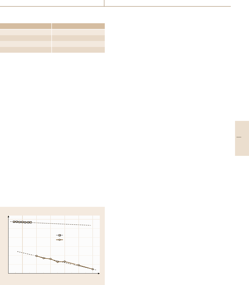
Fig. 10.40 Temperature dependence of the saturation mag-
netization of 3C30 compared with that of Fe
3
O
4
suited for this calibration. Unfortunately, the tempera-
ture dependence of the magnetization of the industrially
available ferrite 3C30 is much worse then that of Fe
3
O
4
(Fig. 10.40).
The calibration constants using Fe
3
O
4
,FeandNi
agree within 1.6%. The reproducibility of the different
magnetization measurements – especially using Fe or
Ni samples – was better than 0.3%. The error due to
eddy currents in the rather long pulse duration (56 ms)
is negligible. The zero signal of the system is less than
10% of the Fe
3
O
4
sample signal, which has the small-
est sample signal. According to these considerations,
one can conclude that the sensitivity of the PFM investi-
gated here is high enough to measure Nd-Fe-B magnet
samples as small as 0.3 g mass, which corresponds to
acubeof3mm×3mm×3mm.SuchaPFM is, however,
also capable of measuring samples with diameters up to
30 mm. It has to be mentioned that the sensitivity for
a certain sample size depends mainly on the coupling
between the sample and the pickup system. Therefore
the sensitivity can be improved by adjusting the pickup
system to a certain sample dimension.
If one works very carefully, an absolute magnetiza-
tion calibration within ±1% is possible. Due to the good
linearity of the analogue measuring electronics avail-
able nowadays and the high resolution of ADC cards
(14 bit), a relative measurement – which is most im-
portant for a quality-control system – with a relative
accuracy better than 0.5% is possible.
10.3.4 Hysteresis Measurements
on Hard Magnetic Materials
Comparison Static Measurement –
Dynamic Measurement
For testing a PFM system a set of commercial
permanent-magnet samples was chosen: isotropic and
anisotropic barium ferrite, anisotropic low- and high-
coercivity Nd-Fe-B magnets. The shape of the samples
was cylindrical: diameter 4 mm, length 5 mm; a demag-
netizing factor of 0.255 was used. In order to allow
a comparison between static hysteresis and dynamic
hysteresis measurements a set of spheres (from the same
batch of samples) were produced at the Technical Uni-
versity (TU) of Vienna.
In order to test the reliability of dynamic meas-
urements pulsed field hysteresis loops where compared
with static loops. In Fig. 10.41 the hysteresis loop as
measured on an isotropic barium ferrite obtained in the
static system at the Centre National de la Recherche
Scientifique (CNRS) in Grenoble is compared with that
Part C 10.3
576 Part C Materials Properties Measurement
80
60
40
20
–20
–40
–60
–80
–8 –6 –4 –2 0 2 4 6 8
0
External field (T)
(emu/g)
Puls
Static
BaFeO HF8/22
isotrop d =4.8 g/cm
3
C = 24mF; t = 15.7 ms
µ
0
H
c
= 0.34T
M
R
= 32.56emu/g
Fig. 10.41 Hysteresis loop as measured on the isotropic BaFeO
HF 8/22 spherical sample
NdFeB 210/220h; t =15.7 ms
µ
0
H
c
= 2.89 (t = 15.7 ms); 2.85 T (static)
M
R
= 110emu/g (t = 15.7 ms); 107.5 emu/g (st.)
150
100
50
0
–50
–100
–10 –8 –6 –4 –2 0 2 4 6 8
–150
(emu/g)
External field (T)
Puls
Static
Fig. 10.42 Room-temperature hysteresis loop of a spherical Nd-
FeB 210/220 magnet measured in a static magnetometer and in the
pulsed field magnetometer
measured in the TU PFM. The use of barium ferrite has
the advantage that there are no eddy currents because
this material is an insulator. The difference is within the
line thickness.
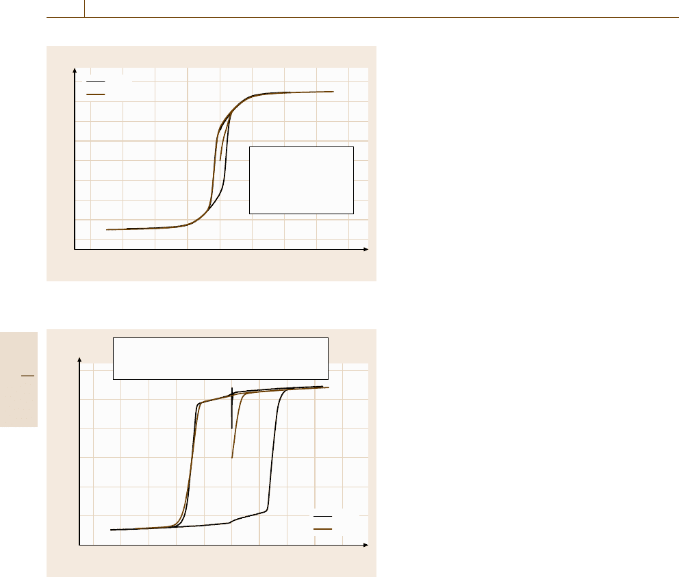
Figure 10.42 also shows for comparison hysteresis
measurements on a Nd-Fe-B magnet as performed in
the PFM (TU Vienna) and in the static magnetometer
(CNRS Grenoble). There are differences in the slope of
the M(H) curve close to the coercivity. It is believed
that this is due to small differences in the sphericity
of the samples. This cannot be due to eddy currents
in the sample because the coercivity value is the same.
This shows that, for sample sizes below 10 mm, and for
the pulse duration here used (15.7 ms) the eddy-current
effects are negligible.
Rare-Earth-Based Magnets
For the following discussion of different types and
shapes of rare-earth-based industrial magnets the room-
temperature hysteresis loops were measured in the
industrial PFM located at TU Vienna.
Figures 10.43 and 10.44 show such a loop as ob-
tained from Vacodym 510 (a Nd-Fe-B magnet); the
agreement between the static and pulsed data is very
good. The applied field, especially in the second half
wave, is not sufficient.
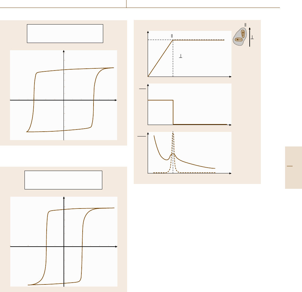
10.3.5 Anisotropy Measurement
Generally the magnetocrystalline anisotropy constants
are determined from measurements on a single crystal
in a torque magnetometer or similar device. Unfor-
tunately single crystals are not available from many
materials. In this case, polycrystalline material can
sometimes be aligned in an external field and then the
magnetization M(H) is measured parallel and perpen-
dicular to the external field. Curves determined in this
way can be fitted, which also allows an estimate of the
magnetocrystalline anisotropy to be made.
Another, sometimes better, possibility is to deter-
mine the magetocrystalline anisotropy field H
a
using
the so-called singular point detection (SPD) tech-
nique [10.44]. The principle of the SPD method is
showninFig.10.45. Single crystals are not neces-
sary for the SPD method, and it allows the deter-
mination of the physically relevant anisotropy field
even for polycrystalline samples. This is especially
important when investigating technically relevant com-
positions, which often consist of many phases and
exhibit rather complex compositions, such as e.g.
Sm(Co, Fe, Cu, Zr)
7.5
which is typical for a so-called
2/17-based technical magnet [10.45]. Additionally
many new technologies, such as rapidly quenching,
hydrogenation disproportionation desorption recombi-
nation (HDDR), nitrogen loading or even thin films,
lead to isotropic material, where single crystals are
not possible in principal. In this case the SPD tech-
nique is the only possibility to determine the anisotropy
field. Up to now this method was restricted to uniax-
ial systems. Recently it was extended to easy plane
systems [10.46], which is essentially for many 3-D-
dominated compounds.
Part C 10.3
Magnetic Properties 10.3 Magnetic Characterization in a Pulsed Field Magnetometer (PFM) 577
Field (kA/m)
–3000 –2000 –1000 1000 2000 3000
1.5
1
0.5
–0.5
–1
–1.5
Vac-510, cube, 15×13×4mm
Pulse: H
C
= 1648kA/m, B
r
= 1.1385TPulse: H
C
= 1648kA/m, B
r
= 1.1385T
Static: H
C
> 1600kA/m, B
r
= 1.198T
µ
0
M (T)
Fig. 10.43 Room-temperature hysteresis loop as obtained
on a cube of Vacodym 510 (an Nd-Fe-B magnet)
Field (kA/m)
–3000 –2000 –1000 1000 2000 3000
1.5
1
0.5
–0.5
–1
–1.5
Vac-510, cylinder, d = 12, h =6
Pulse: H
C
= 1003kA/m, B
r
= 1.383T
Static: H
C
> 1077kA/m, B
r
= 1.384T
µ
0
M (T)
Fig. 10.44 Room-temperature hysteresis loop as obtained
on a cylinder of Vacodym 510 (an Nd-Fe-B magnet)
Limitations of the SPD Method
The SPD method delivers only the anisotropy field H
a
.
This is technically relevant, but it is not sufficient for
a deeper analysis based on the anisotropy constants.
At least the anisotropy energy and its temperature de-
pendence have to be known. If the real saturation
magnetization can be determined the anisotropy energy
Polycrystalline
M
H
H
c
c
H
H
H =H
A
c
H
c
dM
d
2
M
dH
dH
2
H
ext
a)
b)
Fig. 10.45a–c The principle of the SPD measurement for
determining the anisotropy field
can be calculated from H
a
. Unfortunately an accurate
determination of the saturation magnetization is not
simple in hard magnetic compounds, because insuffi-
ciently high fields are available in usual magnetometers.
For this purpose accurate magnetization measurements
up to fields which are comparable to H
a
(or larger) are
necessary, and at different temperatures. When the tem-
perature dependence of the anisotropy energy and that
of the magnetization is known, various types of analy-
sis such as scaling laws can be used in order to come
to an understanding of these data. From such an analy-
sis, information about the origin of the anisotropy can
be deduced.
Studies performed in existing pulsed field systems
(in Vienna and Parma) showed that the SPD method
works well for anisotropy fields up to about 20 T. The
reason for this limitation is that the maximum external
field has to be at least 50% higher than H
a
in order to
make the singularity visible. Another limitation comes
from the fact that at higher fields (above approximately
25 T) the vibrations and consequently the noise of the
high-field system increases drastically, although this is
not yet fully understood. Because the SPD method is
Part C 10.3