Czichos H., Saito T., Smith L.E. (Eds.) Handbook of Metrology and Testing
Подождите немного. Документ загружается.

558 Part C Materials Properties Measurement
a) b) c)
125
35
35
250
1
4
44 44
2
22
4
2
1
6
33
5
6
3
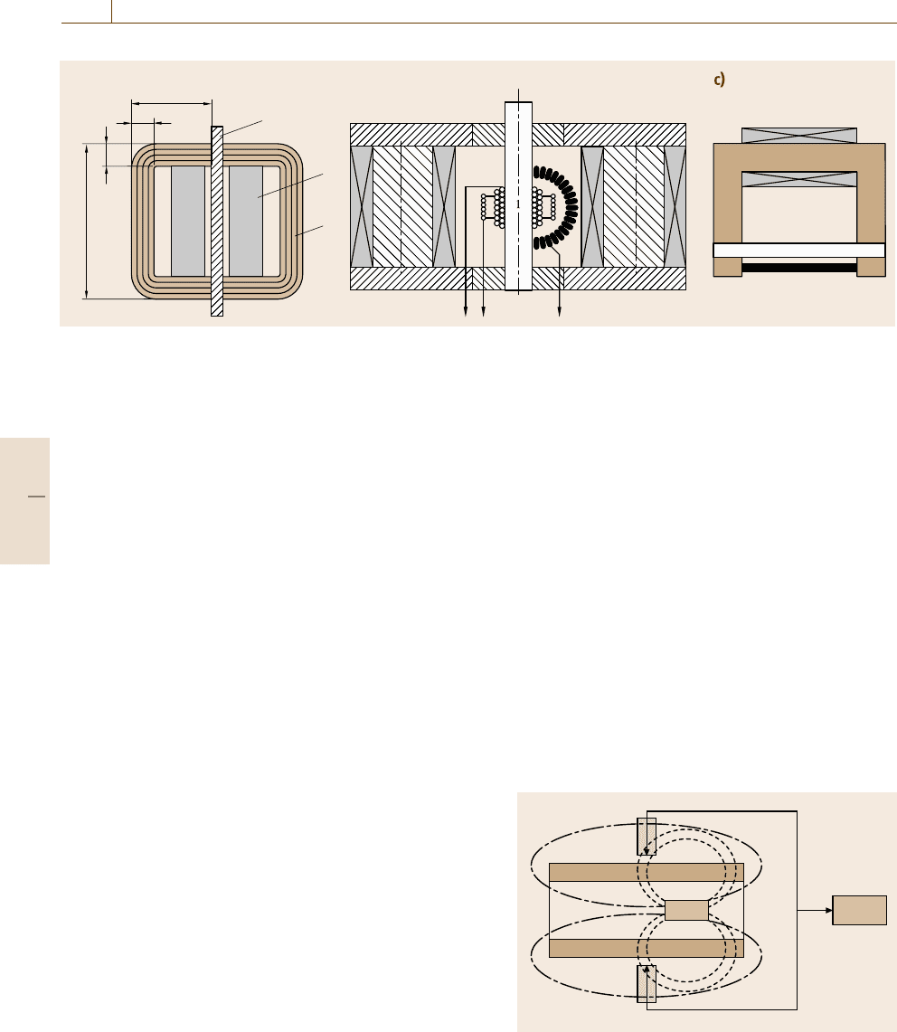
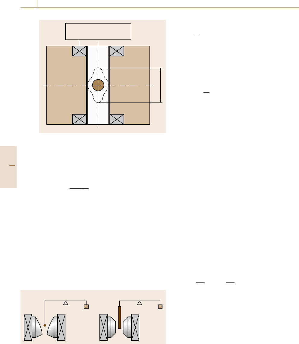
Fig. 10.14a–c Permeameters: IEC Type A (a), IEC Type B (b),FahySimplex(c). 1 – specimen, 2 – yoke frame, 3 – exchangeable
pole pieces, 4 – field-generating coils, 5 – surrounding coil for B or J,6–sensorforH
The type B permeameter uses specimens that are
only 90 mm long, but the maximum field strength is lim-
ited to 50–60 kA/m as the yoke frame saturates above.
Like in the DC ring method, the measuring speed
is often controlled to dB/ dt = const. to minimize the
influence of eddy currents on the measurement results.
Coercimeter. The size and shape of soft magnetic
components often makes it impossible to measure the
complete hysteresis loop. In this case a coercimeter
can be used to determine the coercivity H
cJ
.Asthis
quantity depends sensitively on the microstructure, it is
a good indicator of successful material heat treatment.
The measurement is carried out in an open magnetic
circuit.
A solenoid is used to magnetize and demagne-
tize the specimen. The maximum field strength must
be sufficient to achieve technical saturation, beyond
which the coercivity would remain constant if the mag-
netizing field strength were further increased. This
can be tested by a series of measurements with in-
creasing magnetizing field strengths. The required field
strength depends on the specimen material and shape.
Commercial solenoids provide up to 100–200 kA/m.
Sometimes an additional higher-field pulse is used for
saturation.
After the specimen has been saturated and the
polarity is reversed, the field strength must be in-
creased slowly to avoid errors due to eddy currents
in the specimen. A field sensor detects the stray
field. For a homogeneously magnetized specimen the
stray field vanishes at H
cJ
. Fluxgate probes, Hall
probes or compensated coils can be used as zero-field-
strength detectors. The arrangement of the sensors in
Fig. 10.15 ensures that only the stray field of the spec-
imen and not the field generated by the solenoid is
measured.
Formerly it was usual to align the instrument with
respect to the Earth’s magnetic field. Today shielded
systems are preferred as they are easier to install and
also dynamic noise fields are suppressed.
It is often claimed that coercimeters allow meas-
urement of the coercivity independently of the specimen
shape. For machined components such as parts of re-
lays the coercivity is not uniform due to mechanical or
heat treatment. Complex-shaped parts are not uniformly
magnetized. In these cases the coercimeter provides
only an integral value given by the vanishing stray field
at the sensor position.
AC Hysteresisgraph. An AC hysteresisgraph is mainly
used for ring specimens but also sometimes with fix-
tures that allow measurements of strips. In these cases
3
2
1
3
4
Fig. 10.15 Coercimeter: 1 – specimen, 2 – field-generating
solenoid, 3 – field sensors, 4 – zero detector
Part C 10.2
Magnetic Properties 10.2 Soft and Hard Magnetic Materials: Measurement Techniques 559
the feedback yoke, e.g. a C-core, must be laminated to
avoid eddy currents. The permeability should be high
compared with the permeability of the specimen.
For the winding of the ring specimen the same con-
siderations as for the DC ring method apply.
The simplest version of an AC hysteresisgraph uses
an oscilloscope. The secondary induced voltage is in-
tegrated using a resistor–capacitor (RC) circuit. The
output is displayed as a function of the primary current.
Today this method is mainly used for demonstration
purposes. For material testing, digital data-acquisition
systems are more suitable.
Figure 10.16 shows the operating principle. A pro-
grammable function generator controls a power ampli-
fier that supplies a current I to the primary winding of
the specimen. The current is measured using a shunt
with negligible inductance. From the current and the
magnetic path length l
m
the field strength H can be cal-
culated. The secondary induced voltage is digitized and
integrated to obtain the flux density B.
The measuring conditions have to be defined to
achieve comparable results. Programmable function
generators allow the waveform of B to be defined as si-
nusoidal [10.11]. A sinusoidal H can be easier achieved
using a current output amplifier. Systems with digital
control for B are available up to frequencies of sev-
eral kHz, while uncontrolled systems can reach several
100 kHz or even a few MHz.
Due to an increase of applications for soft mag-
netic materials using pulse-width modulation (PWM),
the interest in measuring systems that allow meas-
urements in the presence of higher harmonics is
growing [10.12]. Function generators with arbitrarily
programmable waveforms can meet these requirements.
After U
1
(t)andU
2
(t) have been recorded, various
evaluations can be carried out. The hysteresis loop and
the total loss can be calculated.
The AC hysteresisgraph can also measure the curve
of normal magnetization, also called commutation
curve. Therefore the amplitude of the magnetizing cur-
rent is successively increased and corresponding peak
values of the field strength and flux density,
ˆ
H and
ˆ
B, are recorded. The amplitude permeability μ
a
(H)or
μ
a
(B) can be calculated from these.
Epstein Frame. The Epstein frame is mainly used by
producers and users of electrical sheet and strip. Many
consignments in industry are based on Epstein values.
The main disadvantage of the method is the demanding
specimen preparation and the large quantity of speci-
men material. The classical Epstein frame had a width
SA
HD
SA
HD
PC
4
3
21
DMA
RAM
N
2
N
1
U
1
U
2
R
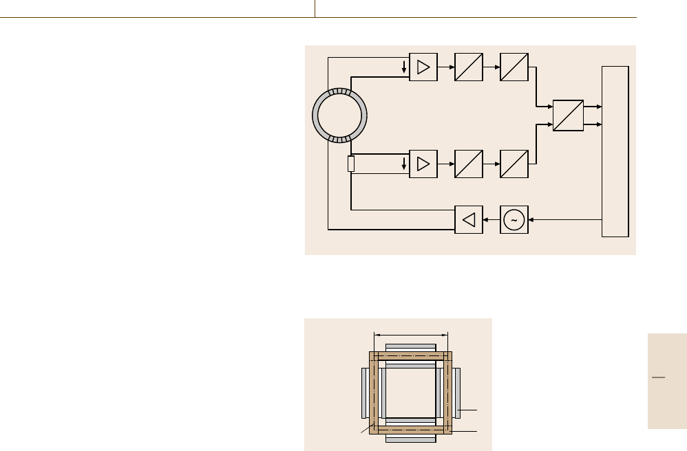
Fig. 10.16 AC hysteresisgraph: 1 – programmable frequency gener-
ator, 2 – power amplifier, 3 – specimen, 4 – transient recorder with
preamplifier and analog-to-digital conversion
250 mm
l
m
= 940mm
2
1
Fig. 10.17 25 cm
Epstein frame:
1–specimen,
2 – magnetizing
and measuring
coils
of 50 cm and required about 10 kg specimen mass. It
has been nearly completely replaced by the 25 cm frame
(Fig. 10.17).
Four coil sets form the frame. Each of them con-
tains two windings: an inner flux measuring winding
and an outer winding to magnetize specimen. The spec-
imen must be cut into strips that are between 280 mm
and 320 mm long and 30 mm ±0.2 mm wide. These are
stacked into the frame so that they overlap alternately in
the corners.
For nonoriented material, one half of the strips is cut
in the rolling direction and the other half perpendicular
to it. The strips cut perpendicular to the rolling direction
must be placed at opposite sides.
Measurements are mainly carried out at power-line
frequencies (50–400 Hz). Rarely the Epstein frame is
also used for quasistatic measurements or up to the
kHz range. Normally the measurements are carried out
under the condition of sinusoidal flux density B. The
excitation is typically limited to
ˆ
B =1.5 T for nonori-
ented and
ˆ
B =1.8 T for oriented material. At higher
excitations, digital or analog feedback control becomes
necessary.
Part C 10.2
560 Part C Materials Properties Measurement
1
2
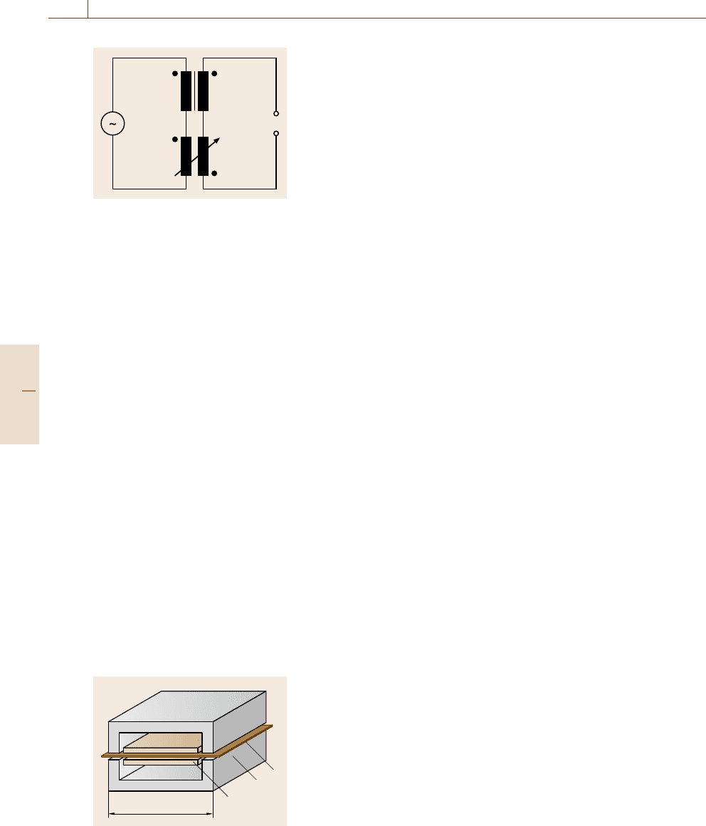
Fig. 10.18 Air-
flux compensa-
tion using an
adjustable mu-
tual inductor:
1–Epstein
frame,
2 – mutual
inductor
To calculate the magnetic field strength H from the
magnetizing current I, the magnetic path length l
m
is re-
quired (10.11). Due to the overlapping edges, l
m
cannot
be determined exactly. Therefore it is set by definition
to 94 cm for the 25 cm frame.
To obtain the polarization J, the air flux that is
generated in the measuring coils must be compen-
sated. A mutual inductor is the conventional solution
(Fig. 10.18). It is adjusted so that the output of the mea-
suring winding is canceled out if no specimen is inserted
in the frame.
Today the Epstein frame is mostly connected to
a data-acquisition system, as shown in Fig. 10.16 for
the AC hysteresisgraph. Then the air-flux correction
can also be carried out by calculating the difference
between a measurement with an empty frame and the
measurement on the specimen.
The Epstein frame is not always used to measure
the complete hysteresis loop. If only loss or perme-
ability data are required, the wattmeter method or the
voltmeter–ammeter method can be applied to the Ep-
stein frame.
Single-Sheet Tester. The single-sheet tester (SST)uses
a yoke to close the magnetic circuit (Fig. 10.19). The
specimen is placed between the two halves of the yoke
inside a set of coils that consists of an inner measuring
coil and an outer coil that applies the magnetizing field.
1
2
3
500 mm
Fig. 10.19
Single-sheet
tester: 1 – spec-
imen, 2 – yoke
frame, 3 – mag-
netizing and
measuring coils
The standardized SST yoke is 500 mm long and
wide. It is designed for sheets with a minimum length of
500 mm. A square specimen allows measurement in and
perpendicular to the rolling direction. Narrower speci-
mens can also be measured. For a sufficient measuring
signal, they should cover at least 60% of the yoke width.
In practice down-scaled frames for smaller specimen
sizes are also used.
To minimize the influence of eddy currents, the
frame must be made of strip-wound cut cores or stacked
isolated sheets. The magnetic losses of the yoke must be
much smaller than the losses of the specimen. Therefore
high-quality electrical steel or iron-nickel alloy is used.
The main advantages compared to the Epstein frame
are lower specimen mass and easier specimen prepara-
tion and installation. The SST allows the measurement
of the same quantities and curves as the Epstein frame.
The electronic part of the instrumentation is principally
the same.
For comparing Epstein frame to SST measurements,
it is essential to explore the relationship between the
two methods [10.13]. The results of an extended com-
parison for grain-oriented steel are compiled in [10.14].
Unfortunately a single correlation factor for all material
grades could not be established.
Normally the field strength is calculated from the
magnetizing current. In this case the magnetic losses of
the yoke and in the gaps to the specimen must be min-
imized. An uncertainty also exists in the determination
of the magnetic path length. To overcome these diffi-
culties, a measurement of the field strength has been
proposed, among others by [10.15], but attempts in this
direction have shown poor reproducibility.
Wattmeter Method. The wattmeter method is used to
measure the specific total loss (power loss) on ring spec-
imens at a given alternating-current (AC) excitation.
The measurement is carried out under condition of sinu-
soidal magnetic flux density. For some specimens this
may require digital control of the magnetizing current
waveform or an analog feedback control of the power
amplifier.
The circuit of the wattmeter method is shown in
Fig. 10.20. Three instruments are necessary: a voltmeter
V
1
displaying the average rectified value (sometimes
scaled to 1.111 times the rectified value), a voltmeter
V
2
displaying the root mean square (rms) voltage and
a wattmeter. All instruments must have high input
impedances and the wattmeter must have a low power
factor.
Part C 10.2
Magnetic Properties 10.2 Soft and Hard Magnetic Materials: Measurement Techniques 561
Prior to a measurement the specimen must be de-
magnetized. Therefore the amplitude of the magnetizing
alternating current is slowly reduced from its maximum
value to zero. The current is then increased to gener-
ate the desired flux density
ˆ
B in the specimen. This is
determined via the average rectified voltage
|
U
1
|
=4 fN
2
A
ˆ
B . (10.23)
The form factor of the secondary waveform must be
verified to ensure a sinusoidal flux density. This is deter-
mined by the ratio of the rms voltage U
2
to the average
rectified voltage U
1
. Additionally an oscilloscope can
be used to monitor the waveform.
For the calculation of the total loss of the specimen,
the power P
i
consumed by the instruments connected to
the secondary winding must be taken into account. As
the voltage shall be sinusoidal it is, to a first approxima-
tion, equal to
P
i
=
1.111 ·
|
U
2
|
2
R
i
, (10.24)
where R
i
is the combined input resistance of all the
instruments connected to the secondary winding. The
total loss P of the specimen is calculated from the read-
ing P
m
of the wattmeter using
P =
N
1
N
2
P
m
−P
i
. (10.25)
The specific total loss is obtained by dividing P by the
mass of the specimen.
Voltmeter–Ammeter Method. The voltmeter–ammeter
method allows the determination of the normal magneti-
zation curve and the amplitude permeability. The circuit
of the method is shown in Fig. 10.21. The instruments
needed are an average-type voltmeter, a root-mean-
W
N
1
V
1
V
2
N
2
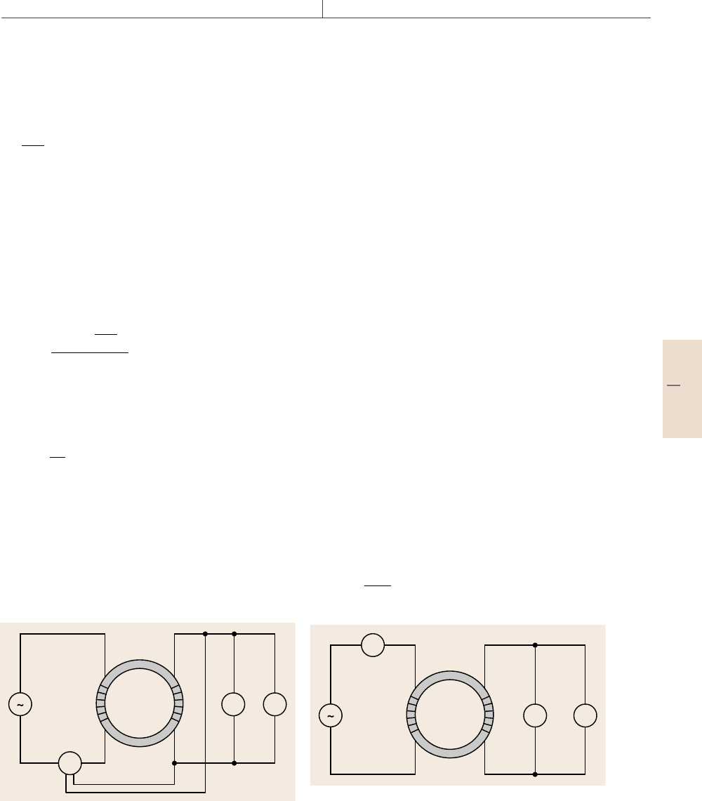
Fig. 10.20 Circuit diagram of the wattmeter method. V
1
is
an average-type voltmeter, V
2
is an rms voltmeter
square-type (rms) voltmeter and an rms or peak-reading
ammeter or a noninductive resistor and appropriate volt-
meter. The voltmeters must have high input impedances.
An oscilloscope can be helpful to monitor the secondary
induced waveform.
If comparable results are desired, either the wave-
form of the primary current or of the secondary voltage
must be kept sinusoidal. Depending on the excitation
and the shape of the hysteresis loop control can be nec-
essary. A sinusoidal H waveform can be achieved by
a current-controlled power amplifier or by a feedback
using a noninductive resistor in the primary circuit. This
can be the resistor used for current measurement. A si-
nusoidal secondary voltage can be achieved by analog
or digital control. The form factor can be determined
by the ratio of the rms voltage to the average rectified
voltage.
The excitation field strength
ˆ
H is calculated from
the current I using (10.15). If I is sinusoidal it can be
measured by multiplying the rms value by the square
root of 2. If the primary waveform is significantly non-
sinusoidal a peak-reading instrument would be required.
In practice this is often ignored and an effective ex-
citation field strength that is lower than the real field
strengthisusedinstead.
Prior to the measurement the specimen is demagne-
tized. Then I is successively increased and the average
rectified value of the secondary voltage is measured.
The flux density
ˆ
B is calculated from (10.23). The nor-
mal magnetization curve can be obtained by plotting
corresponding values of
ˆ
H and
ˆ
B.
The relative amplitude permeability μ
a
can be cal-
culated from
μ
a
=
ˆ
B
μ
0
ˆ
H
(10.26)
A
N
1
V
1
V
2
N
2
Fig. 10.21 Circuit diagram of the voltmeter–ammeter
method. V
1
is an average-type voltmeter, V
2
is an rms
voltmeter
Part C 10.2
562 Part C Materials Properties Measurement
Fluxmeter
5
3
4
SN SN
4
12
7
6
Fig. 10.22 Saturation coil: 1, 2 – windings of a Helmholtz
coil, 3, 4 – permanent magnet material, 5 – fluxmeter, 6 –
specimen; the dashed line (7) marks the maximum speci-
men volume for 1% accuracy
and the rms amplitude permeability from
μ
a,rms
=
ˆ
B
μ
0
√
2
˜
H
, (10.27)
where
˜
H is the rms value of the field strength.
Saturation Coil. The saturation coil, sometimes also
called J
s
-coil or saturation magnetometer, combines the
moment-measuring coil with a permanent-magnet sys-
tem that magnetizes soft magnetic specimens [10.16].
The measuring coil, usually a Helmholtz coil, is con-
nected to a fluxmeter.
When a specimen with volume V is inserted into
the coil, it is magnetized and the magnetic dipole mo-
ment j can be obtained from the flux measurement
using (10.9). If the field strength is sufficiently high, the
33
a) b)
1
1
2
2
Fig. 10.23 (a) Faraday method and (b) Gouy method, 1 – specimen,
2 – electromagnet poles, 3 – balance
saturation polarization can be determined through
J
S
=
j
V
. (10.28)
Of course the specimen can also be withdrawn from the
coil for measurement, but the rotation method, which is
frequently used with the moment-measuring coil, can-
not be used.
For lower field strength the relative permeability can
be calculated using
μ
r
=1 +
J
H
i
. (10.29)
The inner field strength H
i
of the specimen must be
determined from the magnetizing field strength, taking
into account the demagnetization factor.
The main applications of the method are the de-
termination of the saturation polarization of specimens
made of nickel or nickel alloys and the determination of
the cobalt content in hard metal specimens.
Magnetic Scales. Magnetic scales or balances measure
the force that acts on a magnetic specimen in a nonho-
mogeneous field [10.17]. From this force the following
quantities can be determined
•
magnetic moment m and magnetic dipole moment
j =μ
0
m,
•
magnetic permeability μ and magnetic susceptibil-
ity χ = μ −1.
As the specimens can be easily heated or cooled, the
methods can also be used to measure the temperature
dependencies of the properties. This includes the de-
termination of Curie and Néel temperatures and the
observation of other phase transitions.
Faraday Method. The force acting on a small specimen
with volume V in a magnetic field with gradient dH/dy
is
F = j
dH
dy
= Vχ H
dH
dy
. (10.30)
The specimen is suspended from the scale so that
it is located between the poles of an electromagnet
(Fig. 10.23). The pole caps are shaped such that the
product H(dH/ dy) is constant over the whole volume
(gradient pole caps), so that the force is proportional to
the susceptibility χ. The Faraday method is suitable for
all kind materials, especially ferro- and ferrimagnetic
specimens. It allows the determination of the satura-
tion polarization J
S
for soft magnetic materials if the
specimen shape is appropriate.
Part C 10.2
Magnetic Properties 10.2 Soft and Hard Magnetic Materials: Measurement Techniques 563
Gouy Method. A long bar-shaped specimen is sus-
pended from the scale so that one end is located
between the poles of an electromagnet generating a field
strength H. The other end outside the poles is only af-
fected by the stray field strength H
s
H. The force
acting on the whole sample is
F =
1
2
Aχ
H
2
−H
2
s
≈
1
2
Aχ H
2
, (10.31)
where A is the cross-sectional area of the specimen. The
Gouy method is mainly used for para- and diamagnetic
materials including liquids and gases.
Impedance Bridges. If an alternating current is sup-
plied to a coil that contains a ferromagnetic core,
a phase shift between magnetic field strength and flux
density occurs. The magnetic material can be character-
ized by the complex permeability
μ =μ
−iμ
. (10.32)
The impedance of the filled coil is
Z = R+iωL = ωμ
L
0
+iωμ
L
0
(10.33)
if losses and additional phase shifts that are not caused
by the core material are neglected. L
0
is the inductance
of the measuring winding without the magnetic core.
For a cylindrical specimen, it can be calculated as
L
0
=
μ
0
2π
ln
D
d
hN
2
, (10.34)
where D is the outer diameter, d is the inner diameter
and h the height of the coil, and N is the number of
turns of the winding.
The loss angle δ and the Q-factor can be determined
from
tan δ =
R
ωL
=
1
Q
=
μ
μ
. (10.35)
For the determination of Z, various impedance bridges
are available from electrical measuring techniques; they
differ in sensitivity and frequency range. For the char-
acterization of magnetic components, suitable circuits
are used in a frequency range of approximately 1 Hz to
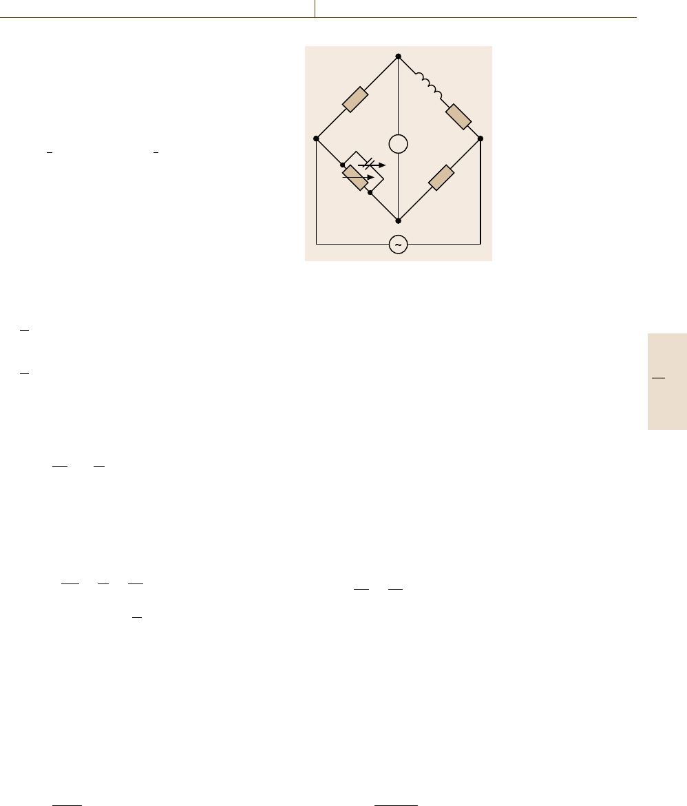
100 MHz. A basic circuit is the Maxwell–Wien bridge
showninFig.10.24. It can be used from about 50 Hz to
100 kHz.
The specimen, a ring core that is uniformly wound
with a single winding, is defined by its equivalent cir-
cuit diagram consisting of R
x
and L
x
. The bridge is
balanced if
R
x
=
R
1
R
2
R
v
(10.36)
A
R
1
R
v
C
v
R
2
R
x
L
x
Fig. 10.24
Maxwell–Wien
bridge
and
L
x
= R
1
R
2
C
v
. (10.37)
R
x
consists of the loss R caused by the magnetic core
and the loss in the winding
R
x
= R +R
0
. (10.38)
The loss in the winding R
0
is basically the DC re-
sistance if the frequency is not too high, and can be
obtained from a resistance measurement.
The inductance L
x
is composed of the leakage in-
ductance L
σ
and the inductance of the specimen L
L
x
= L
σ
+L = L
σ
+μ
L
0
. (10.39)
For large permeabilities the leakage inductance L
σ
can
be neglected and μ
can be calculated to
μ
=
L
L
0
≈
L
x
L
0
. (10.40)
Otherwise the real inductance L
0
of the winding should
be considered. L
0
can be measured on an air-core coil:
a winding that is wound on a nonmagnetic core and
that has the same dimensions as the measuring wind-
ing. It can be assumed for small permeabilities that the
stray field would be the same, regardless whether there
is a core or not. With
L
0
≈ L
σ
+L
0
, (10.41)
it follows that
μ
≈1+
L
x
−L
0
L
0
. (10.42)
Part C 10.2
564 Part C Materials Properties Measurement
At higher frequencies the resistance of the winding dif-
fers from the DC resistance due to the skin effect. In
this case mutual inductance bridges provide more accu-
rate results, as in these circuits the resistance of the wire
does not enter the measuring result. The specimens must
be equipped with two windings. Suitable circuits are the
Wilde [10.18] and Hartshorn bridges. Further methods
are compiled in [10.19].
Measurement of Magnetostriction. Magnetostriction
comprises all dimensional changes of a specimen that
are caused by changes in magnetization. For both the
volume-invariant shape effect and the volume magne-
tostriction, a measurement of a change of the specimen
length in one or more dimensions can be carried out.
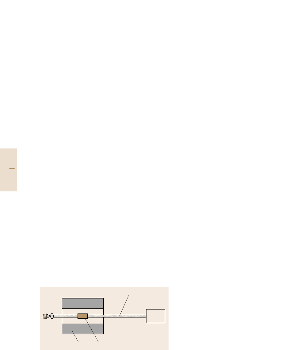
The specimen is placed in the center of a solenoid,
which generates the magnetic field required. The
change in length is transferred via a rod to a dis-
placement transducer that is located outside the stray
field of the solenoid. The material of the rod must be
properly chosen to keep the outer force acting on the
specimen as small as possible and to avoid errors due
to temperature-induced changes in length. Capacitive,
inductive or optical sensors are used to measure the
displacement.
Another method uses strain gauges that are directly
attached to the specimen. To cancel out errors due to the
magnetic and thermal properties of the strain-sensing
element, a second element of the same type can be at-
tached to a substrate that shows no magnetostriction but
is exposed to the same environment. The two sensing
elements can be connected to opposite paths of a bridge
circuit.
A third method uses a single-mode optical fiber
attached to the specimen. The fiber is part of an inter-
ferometer. The change in length is detected as a phase
shift in the electromagnetic wave propagating in the
fiber [10.20].
12
3
4
Fig. 10.25 Magnetostriction measurement: 1 – solenoid, 2
– specimen, 3 – specimen rod, 4 – displacement transducer
The volume magnetostriction can also be measured
by the conventional measuring method for volumetric
content. The specimen, immersed in a liquid, is exposed
to the magnetic field.
Magnetostriction is an important parameter in many
applications of electrical steel. A comprehensive de-
scription of magnetostriction measuring methods for
these materials can be found in [10.21].
Measurement of the Hysteresis Loop
of Amorphous or Nanocrystalline Ribbons
Sample Shape. In the case of soft magnetic ribbons the
hysteresis loop can be measured on
1. open ribbons, in which case the demagnetizing fac-
tor has to be considered,
2. toroids.
The temperature the loop is measured is also important.
In the case of low- or high-temperature measurements
the system has to withstand the desired temperature.
In principle, magnetic measurements should always
be carried out on a toroid instead of open ribbons be-
cause only then is a closed magnetic circuit realized.
For ribbons this method has the disadvantage that the
material is not in a stress-free state – there is a tensile
stress on the outer surface and comprehensive stress on
the inner surface. Another possibility is to use a single
straight ribbon but then the demagnetizing field has to
be considered.
Hysteresis Loop on a Single Ribbon. When hystere-
sis is measured on a single open ribbon a well-defined
external stress can be applied. Temperature-dependent
measurements are possible, although technically more
complex. The facilities necessary for measuring the hys-
teresis loop are field coils, a compensated pickup coil,
a current source, an ammeter and an integrator (flux-
meter). For the measurement of coercivity a Helmholtz
coil is mainly used, and for the measurement of satura-
tion magnetization the field is applied by a cylindrical
coil producing a sufficient high field. The coils are en-
ergized by a computer-controlled power supply.
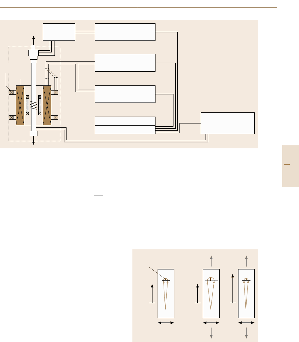
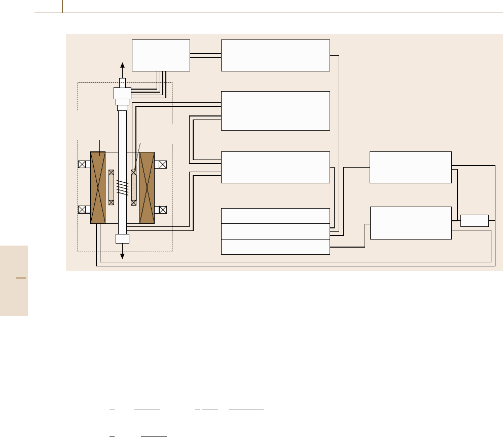
The devices are connected and controlled by a data-
acquisition and control unit, forming a full automatic
hysteresis-loop system. Figure 10.26 shows as an exam-
ple a set up for such a hysteresis measurement on single
strip ribbons.
In this case a compensated pickup system has to be
used. When the pickup and the compensation coils are
connected, so that the induction signals due to the field
Part C 10.2
Magnetic Properties 10.2 Soft and Hard Magnetic Materials: Measurement Techniques 565
Digital voltmeter
(Keithley K2000)
Digital amperemeter
(Keithley K196)
Computer
Power amplifier
(KEPCO BOP 100-4M)
IEEE GPIB card
Fluxmeter integrator
Steingroever EF4
Input B 10 kΩ
Out
5 kHz bridge
amplifier
Force sensor
Helmholtz
coil
Cylindrical
coil
Cryostat
I (A)
U
ind
Fig. 10.26 Hysteresisgraph for a quasistatic hysteresis measurements and devices for force measurement for single
ribbons
are subtracted, the remaining signal will be proportional
to the magnetization M
u
ind
=u
pick
−u
comp
=−N
pick
μ
0
A
rib
dM
dt
. (10.43)
Magnetostriction. Magnetostriction on thin ribbons
can be measured by direct and indirect methods. Di-
rect methods are, for example, measurements with
strain gauges, capacitance transducers or interferom-
eters. All these methods have the disadvantage that
sample preparation is difficult. Strain gauges are lim-
ited in sensitivity (Δλ/λ
0
=±1×10
−6
) . Additionally
the saturation magnetostriction constant has to be deter-
mined from measurements parallel and perpendicular to
the external field.
Indirect methods are the Becker–Kersten method
[10.22] and the small-angle magnetization-rotation
(SAMR) method [10.23]. With the Becker–Kersten
method the magnetostriction is determined from the
stress dependence of the hysteresis loop. The SAMR
method was developed by Narita et al., especially for
ribbon shaped materials with a small magnetostriction
constant.
The SAMR Method. First of all a DC field is applied in
the ribbon axis. This field should magnetically saturate
the sample. Then a smaller AC field (with frequency f )
is applied perpendicular to the ribbon axis. This causes
a small rotation (small angle) of the magnetization vec-
tor out of the ribbon axis. A small induction signal
with double the frequency of the AC field is now de-
tected by a pickup coil (Fig. 10.27a) and measured by
a lock-in amplifier. Applying an external stress to the
ribbon causes, for ribbons with positive magnetostric-
tion, a decrease in the deflection angle, whereas for
samples with negative magnetostriction the angle in-
creases (Fig. 10.27b). Now the DC field H
DC
is changed
in such a way that the deflection angle and therefore
a) b) c)
Induction signal Applied stress
DC field
AC field
Fig. 10.27a–c MagnetostrictionmeasurementbytheSAMR
method
Part C 10.2
566 Part C Materials Properties Measurement
Digital voltmeter
(Keithley 196 DMM)
DC power supply
45 A
(Siemens)
Digital voltmeter
(Keithley K2000)
Power amplifier
(KEPCO BOP
100-4M)
Lock-in-amplifier
(EG G)
Computer
IEEE GPIB card
ADDA 12 card
Shunt
5 kHz bridge
amplifier
Force sensor
Cylindrical
coil
(DC field)
Perpendicular
coil (AC field)
Cryostat
Out
In
I
AC
Fig. 10.28 Experimental set up for magnetostriction measurement by SAMR method
also the induction signal go back to their initial value
(Fig. 10.27c). The variation of the DC field ΔH
DC
and
the variation of the external stress Δσ determine the
magnetostriction constant. To get an accurate value this
procedure has to be repeated step by step with increas-
ing stress. From the balance of the magnetic and the
magnetoelastic energy one can calculate the saturation
magnetostriction as
λ
s
=−
1
3
J
s
ΔH
DC
Δσ
f
=−
1
3
Φ
sat
A
rib
ΔH
DC
ΔF/A
rib
=−
1
3
Φ
sat
ΔH
DC
ΔF
, (10.44)
where J
s
is the saturation polarization of the ribbon
at a certain temperature. The polarization J
s
is pro-
portional to α/ A
rib
, where α is the output value of
the fluxmeter and A
rib
is the cross section of the sam-
ple. The value of Δσ is given by ΔF/A
rib
. According
to the equation above the magnetostriction then be-
comes completely independent of the cross section. The
magnetostriction then depends only on the exact meas-
urement of the magnetic flux (saturation value Φ
sat
),
on the measurement of the force F(ΔF = F
1
−F
2
,
by the force-sensor bridge) and on the measurement
of the magnetic field H
DC
(ΔH
DC
= H
DC
1
−H
DC
2
).
Figure 10.28 shows as an example a possible set up
for magnetostriction measurements using the SAMR
method.
This method was used successfully to determine the
magnetostriction of many amorphous materials [10.24].
It delivers comparable results and achieves a sensitivity
in the magnetostriction constant of up to 10
−9
[10.25].
Magnetoimpedance. Relevant information about trans-
versal magnetization processes in magnetic materials
can be obtained from the field H and frequency f
dependence of the complex impedance (Z = R +iX).
In soft magnetic high-permeability materials, large
variations of Z (for current frequencies larger than
100 kHz) have been observed upon the application of
relatively small magnetic fields, the so-called giant
magnetoimpedance effect (GMI) [10.26–28]. Gener-
ally magnetoimpedance is based on the application
of an AC field caused by an inhomogeneous field
distribution in a conducting material with a high
permeability. This effects depends therefore on the
frequency, and on the applied field, but also on ma-
terial parameters such as the conductivity as well
as the permeability – which depends additionally on
the applied DC field – of the material. Additionally
the sample geometry (ribbons, wires) as well as lo-
cal fluctuations of material parameters have to be
considered.
Part C 10.2
Magnetic Properties 10.3 Magnetic Characterization in a Pulsed Field Magnetometer (PFM) 567
For these measurements one needs: a digital lock-
in amplifier working over a broad frequency range,
a power supply, a dynamic signal analyzer, some form
of digital multimeter, and a computer with an inter-
face for the data acquisition. The lock-in amplifier
supplies the AC signal and is also employed to read
the real and imaginary voltage drop across the sample.
In GMI measurements, a constant-current source sup-
plies a constant AC current flowing along the sample
in order to assure a constant circular magnetic field.
As the generator of the lock-in works generally as
a constant-voltage source, either one uses an external
constant-current source or one measures the AC voltage
drop across a resistor R, which determines the actual
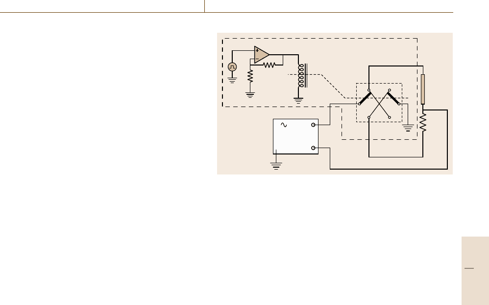
current through the sample as shown in Fig. 10.4.In
this experiment not only the AC current has to be con-
trolled but also the phase signal. In order to do this
a two-position relay controlled by a computer can be
used; the two positions correspond to calibration and
measurement. In the calibration position (Fig. 10.29),
the signal is applied to the sample, which is in series
with a grounded resistor and the lock-in measures the
voltage across the resistor, which can be controlled to
maintain a constant intensity value. In the measurement
position (Fig. 10.29), the relay inverts the ground and
signal position so that the signal is applied to the re-
sistor, and the sample is grounded. The lock-in thus
measures the sample’s signal. The voltage over the sam-
ple is measured in a four-probe configuration and the
contacts with the sample are made using silver conduct-
ing ink.
The magnetic DC field, which is applied along the
sample’s length, is supplied by a pair of Helmholtz
Electronic device
Measuring
position
Relay
Calibrating
position
Sample
Output
Lock-in
EG&G 5310
Input
R
R
R
Fig. 10.29 Schematic diagram of the electric necessary to measure
the magneto-impedance
coils connected to a power supply, which operates as
a current source. The current passing through the coils
is measured by a multimeter. With this equipment the
magnetoimpedance as a function of frequency and ex-
ternal DC field can be measured. Furthermore, the
experimental set up can be completed by a dynamic
signal analyzer, which allows one to follow the time
dependence of the impedance after a sudden rearrange-
ment of the domain configuration [10.29]. After the
magnetic field is switched off (t = 0), it is possible to
measure both R and X from t
0
up to t
1
by connecting
the DC output of the lock-in to one of the inputs of the
signal analyzer. The sensitivity is high enough to notice
relative variations as low as 0.1%. With this extension
magnetic disaccommodation of the magnetoimpedance
can also be measured.
10.3 Magnetic Characterization in a Pulsed Field Magnetometer (PFM)
Industrial producers and consumers of magnets are in-
creasingly demanding systems which allow fast and
reliable online tests of the hysteresis properties of
magnets. High-quality permanent magnets based on
rare-earth intermetallic compounds such as Sm-Co and
Nd-Fe-B exhibit coercivities of 2 T and sometimes
even higher, which are too high for Fe-yoke-based sys-
tems [10.7,30].
The current conventional methods, namely vibrating-
sample magnetometers (VSMs) and permeameters have
limiting physical constraints. Fe-yoke-based VSMsand
permeameters offer only a limited field strength (max-
imum 1.5 T). Permeameters are used for measuring the
second quadrant of the hysteresis loop and need care-
ful sample preparation (cutting, polishing). VSMsthat
use a superconducting solenoid require liquid helium
for cooling and are generally expensive; additionally
standard magnetometers are currently only available for
relatively small samples (mm sizes). Additionally su-
perconducting solenoids allow only limited field-sweep
rates (dH/dt rates) which are of the order of T/min.
Generally all these systems need special sample prepa-
ration and measurement times that are unacceptable for
industrial purposes. It will be shown that a PFM is
Part C 10.3