Czichos H., Saito T., Smith L.E. (Eds.) Handbook of Metrology and Testing
Подождите немного. Документ загружается.

588 Part C Materials Properties Measurement
11.7 Optical Sensing..................................... 649
11.7.1 Distance Measurement.................. 649
11.7.2 Displacement Measurement .......... 651
11.7.3 3-D Shape Measurement............... 651
11.7.4 Flow Measurement....................... 652
11.7.5 Temperature Measurement............ 653
11.7.6 Optical Sensing for the Human Body 655
References .................................................. 656
11.1 Fundamentals of Optical Spectroscopy
11.1.1 Light Source
There are many light sources for use in scientific and in-
dustrial measurements [11.1–4]. This subsection deals
with the features of various light sources. For source
selection, various characteristics should be considered,
such as wavelength range, radiant flux, directionality,
stability in time and space, lifetime, area of emission,
and temporal behavior. Spectral output, whether it is
a continuum, a line, or a continuum-plus-line source,
should also be considered. No light source covers all
wavelengths simultaneously from the ultraviolet (UV)
to infrared (IR) wavelength region. Although a black-
body with extremely high temperature could realize
such an ideal light source, the melting point of the ma-
terials that form the electrodes must be extremely high,
Far-UV Near-UV
X-ray
Ultraviolet (UV)
Vacuum (UV)
Visible
Near-IR Mid-IR Far-IR
Infrared (IR)
200 300 380 nm5 nm 750 nm
1000 nm100 nm10 nm
3.0 μm
10 μm 100 μm
3mm25 μm
Synchrotron radiation
Terahertz radiation
Blackbody furnace
Carbon arc
Nernst globar
Globar (SiC)
High-pressure Hg lampHigh-pressure Hg lamp
W lamp
Xe arc lamp
Gas discharge lamp
(He, Ne, Ar, Kr, Xe)
D
2
lamp
Semiconductor laser
UV LD, LED
(365–375 nm)
Blue LED
White LED
Ar Laser
(514 nm)
He-Ne laser
(632 nm)
Gas laser
Nd
3+
YAG
NH
3
, HCN, H
2
O
CO
2
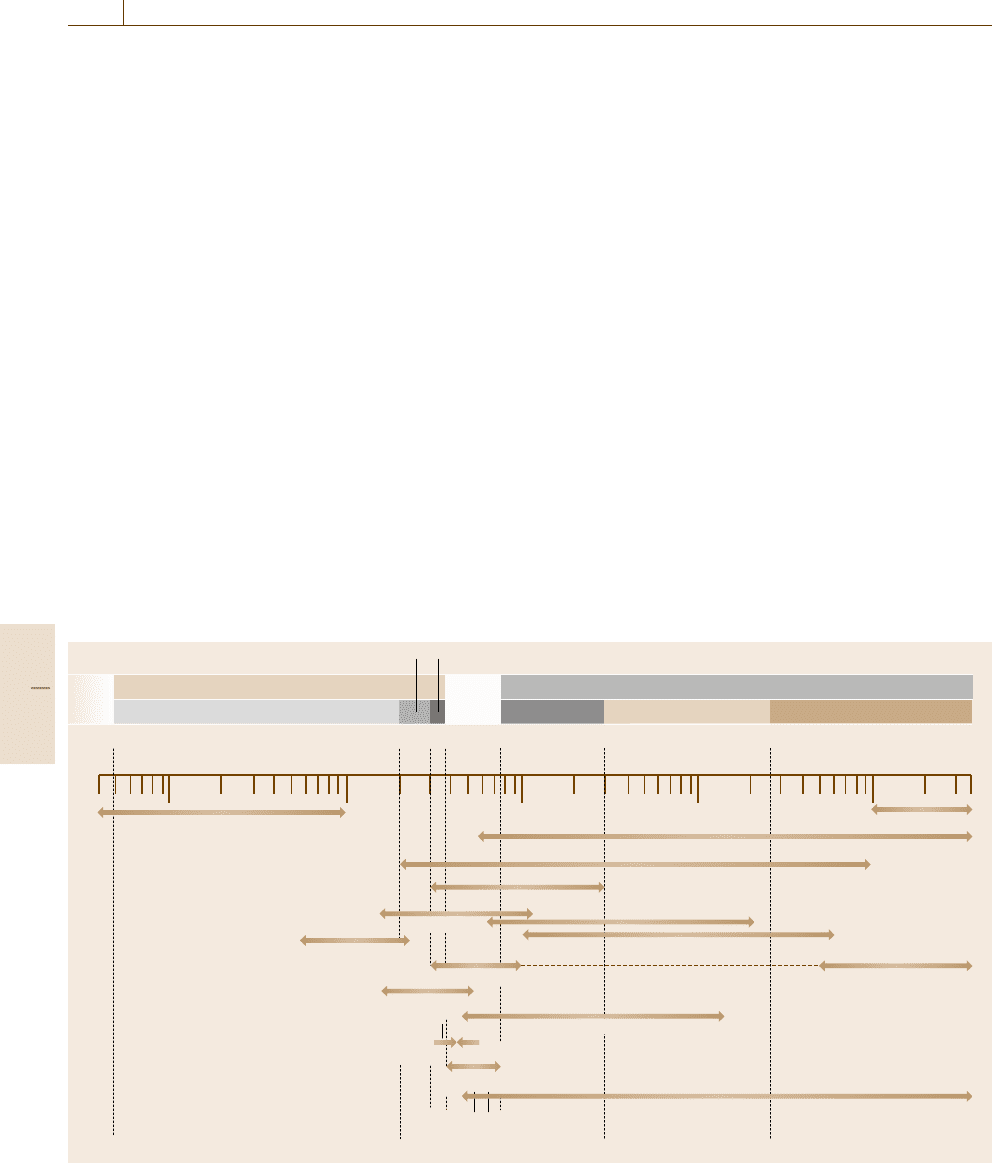
Fig. 11.1 Wavelength regions of various light sources
and it is impossible to construct it. We, therefore, should
select an adequate source that covers the required wave-
length region from the UV to the IR region. In general,
we use a gas discharge lamp for the UV region and a ra-
diation source from a solid for the visible and the IR
region. At present, many kinds of light sources cover-
ing each wavelength region, as shown in Fig. 11.1, are
available. Those can be broadly classified into: 1) ther-
mal radiation sources such as a tungsten filament lamp
(W lamp) and an incandescent lamp in the IR region
such as a Nernst glower and a glouber, 2) arc lamps
such as a high-pressure xenon arc lamp (Xe lamp),
a high- or low-pressure mercury lamp, a hydrogen and
a deuterium-hydrogen arc lamp (D
2
lamp) based on
electrical discharge in gas, 3) a light-emitting diode
(LED)oralaserdiode(LD) basing on emission from
Part C 11.1
Optical Properties 11.1 Fundamentals of Optical Spectroscopy 589
the pn junctuon of a semiconductor, and 4) narrow-
line sources using an atomic or molecular transition
lines such as a hollow cathode discharge tube and an
electrodeless discharge lamp, including many kinds of
lasers. Recently, synchrotron radiation and terahertz
emission in the far-UV and submillimeter wavelength
regions, respectively, have become available, mainly for
research purposes.
Among those light sources, one of the most stable,
well-known, and intensively characterized in the visible
and the near-IR region is the W lamp (or tungsten-
filament white bulb). Although the spectral emissivity
of tungsten is about 0.5 in the visible region and about
0.25 in the near-IR region, its spectral distribution of
emission agrees relatively well with that of Planck’s
blackbody radiation. The W lamp can be used in an ar-
bitrary color temperature up to 3100 K. However, more
than 90% of the total emission energy is distributed in
the IR wavelength region and less than 1% in the UV re-
gion below 400 nm. Therefore, it cannot be used in the
UV region. The UV region, however, is especially im-
portant in the field of spectrochemical analysis. To cover
the lower energy in the UV region, the D
2
lamp is used
in combination with the W lamp, although the D
2
lamp
has some problems in terms of emission stability and
ease of operation.
For the tungsten white bulb, a vacuum bulb is used
for color temperatures up to 2400 K. A gas bulb sealed
in nitrogen, argon, or krypton gas at around 1 atm is
used for color temperatures between 2000 and 2900 K.
For color temperatures around 3100 K, a tungsten-
halogen bulb is used. In order to prevent deposition of
tungsten atoms onto the inner surface of the bulb, the
pressure of argon or krypton gas is maintained at sev-
eral atmospheres and the bulb is made mechanically
rigid by using quartz. Furthermore, by mixing a small
amount of halogen molecules such as I
2
,Br
2
,orCl
2
into the gas, the decrease in transmittance due to the de-
position of tungsten atoms on the inner surface of the
bulb is effectively prevented. This process is known as
a halogen cycle. To make the process effective, the bulb
temperature must be kept relatively high. The lifetime
of the lamp is extended by about two times compared to
a lamp that does not benefit from this process.
One of the most significant developments in light
sources during the last 15 years is blue or UV LEDs.
Blue and UV LDs have even appeared. The blue LED is
used mainly for traffic signals and the blue and UV LD
as recording or read-out light sources for circular discs
and digital videodiscs. However, they also have great po-
tential as light sources for scientific measurement. At
present, UV LEDsandUV LDs with an emission wave-
length around 365–375 nm are commercially available.
Such LEDsandLDs are based on emission from gallium
nitride (GaN) materials. GaN is a direct-transition-type
semiconductor and has an energy gap of about 3.44 eV at
room temperature, which corresponds to the UV emis-
sion wavelength. By adding indium (In) and aluminum
(Al) to the GaN, one can obtain blue emission. When us-
ing gallium phosphorus (GaP) instead of GaN materials,
and when adding In and Al, one can obtain green emis-
sion. When adding only In, one can obtain red emission.
Another light source to be noted is the white LED,which
has been commercialized rapidly as a back-illumination
light source for liquid crystal displays. The white LED
consists of a blue or UV LED and fluorescent materials
deposited onto the LED in the same package. The blue
or UV LED is used as an excitation light source for the
fluorescent materials, which may be yttrium aluminum
garnet (YAG ) materials or some kinds of rare-earth com-
pounds. The excitation light and fluorescence together
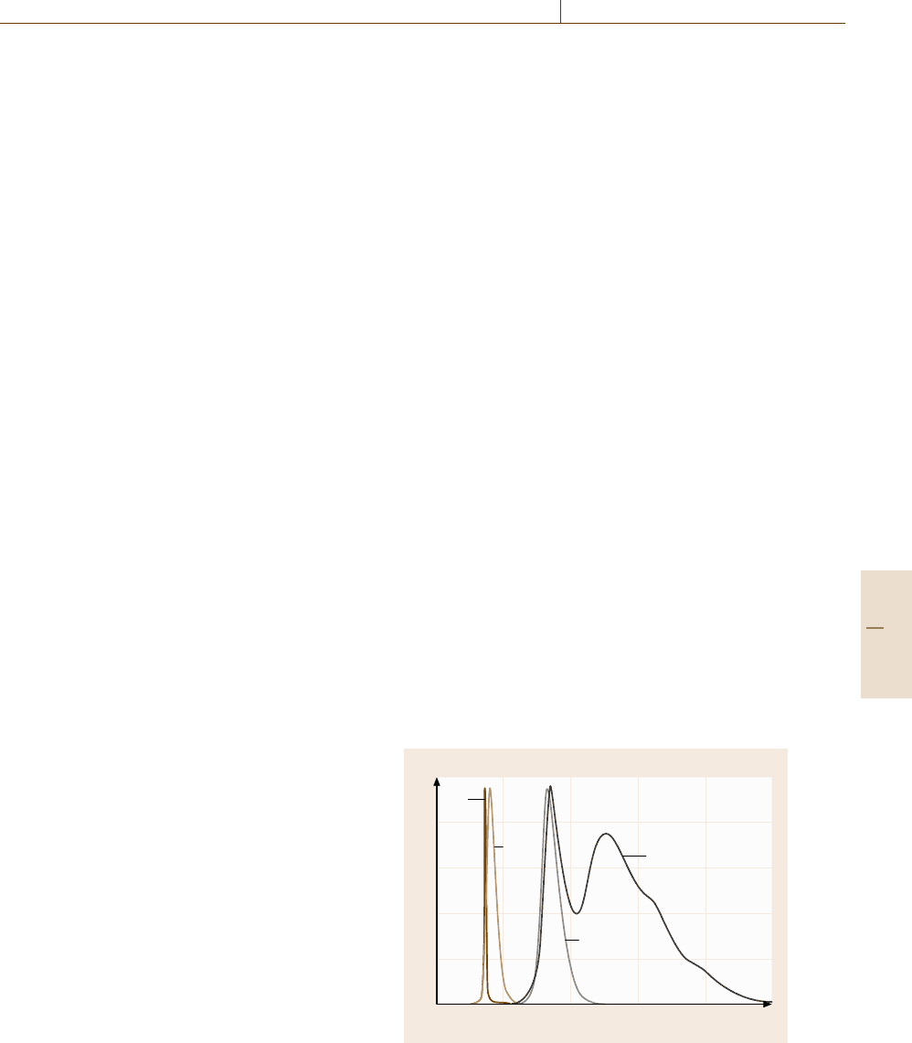
make the white light. A high-power white LED exceed-
ing 5 W has been developed. Figure 11.2 shows typical
emission spectra of such LEDs and that of the UV LD.
For scientific measurements or for spectrochemical
analyses, a pulsed light source in the UV wavelength
region is important, for example, for distance measure-
ments, fluorescence lifetime measurements, and so on.
For such requirements, a picosecond light pulsar with
a pulse duration around 60 ps, a wavelength of 370 nm,
and a repetition frequency of 100 MHz has appeared
on the market. However, in general, such a laser has
a problem in wavelength selection and cost. To solve
such problems, a technique to drive the Xe lamp in
1
0.8
0.6
0.4
0.2
0
300
Wavelength (nm)
400 500 600 700 800
Intensity (arb. units)
UV
LD
UV
LED
Blue LED
White LED
Fig. 11.2 Emission spectra of a blue, UV, and white LED,
and that of a UV LD
Part C 11.1
590 Part C Materials Properties Measurement
a nanosecond pulsed mode has been developed [11.5–7].
A technique to modulate the Xe lamp sinusoidally has
also been developed so that it can be used in combina-
tion with a lock-in light-detection scheme. The UV or the
blue LED also can be driven with a large current pulse,
resulting in a pulse duration less than 1.5 ns [11.8–10].
11.1.2 Photosensors
This subsection deals with sensing features of various
photosensors [11.1–4]. The photosensor is the terminol-
ogy used for a photodetector when used for a sensing
purpose. Photodetectors can be broadly classified into
quantum-effect (QE) detectors (or photon detector) and
thermal detectors. The QE detector can be subdivided
into an external and an internal type, as shown in Ta-
ble 11.1 Furthermore, the internal type is subdivided
into a photoconductive (PC) detector, a photovoltaic
(PV) detector, and a photoelectromagnetic (PEM)de-
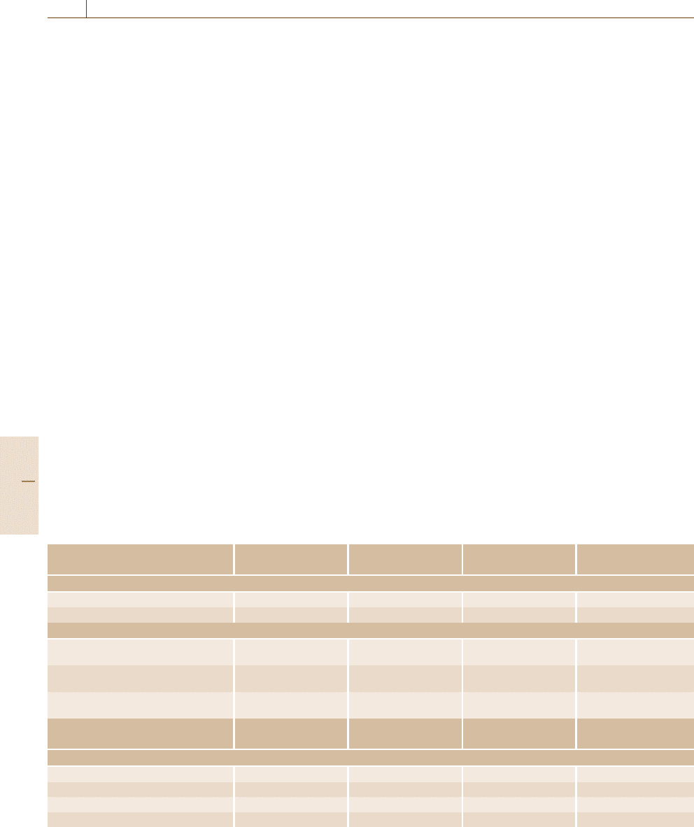
tector. Figure 11.3 shows the spectral response of each
photodetector.
The operating principle of the external QE detector
is based on the photoelectron emissive effect of a metal.
Representative detectors are a phototube (PT)and
a photomultiplier tube (PMT). A variety of photosen-
sitive cathodes, having different spectral responses, are
available from the UV to the near-IR wavelength region.
A photocathode whose principal component is gallium
arsenic (GaAs) gives high quantum efficiency and has
sensitivity at longer wavelengths exceeding 1 μm. The
Table 11.1 Classification of photosensors
Type D
∗
Spectral range Linear range Rise time
(cm Hz
1/2
W
−1
) (nm) (decades) (ns)
External quantum-effect detector (photon detector)
Phototube (PT) 10
8
–10
10
200–1000 4.5–5.5 0.3–10
Photomultiplier tube (PMT) 10
12
–10
18
200–1000 5.0–6.0 0.3–15
Internal quantum-effect detector
Photoconductive detector (PC)
(PbS, InSb, Ge)
10
9
–10
12
750–6000 5.0–6.0 50–10
6
Photovoltaic detector (PV)
(Si photodiode)
10
8
–10
12
400–5000 3.0–4.0 10
3
–10
6
Photoelectromagnetic detector (PEM)
(InSb)
D
∗
Spectral range Linear range Time constant
(cm Hz
1/2
W
−1
) (μm) (W) (ms)
Thermal detector
Thermocouple 10
8
–10
9
0.8–40 10
−10
–10
−8
10–30
Thermistor (Bolometer) 10
8
–10
9
0.8–40 10
−6
–10
−1
10–30
Pneumatic detector (Golay cell) 10
8
–10
9
0.8–10
3
10
−6
–10
−1
2–50
Pyroelectric detector TGS, PZT 10
7
–10
8
0.3–10
3
10
−6
–10
−1
5–1000
PT consists of two electrodes sealed in a vacuum tube:
a photocathode and an anode. The PT had been used
for light sensing at relatively high powers. At present, it
is mainly used for measuring ultra-short light pulses by
taking advantage of its simple structure. Such a special
PT is known as a biplaner type. The PMT consists of
the photocathode, the anode, and 6–12 stages of dyn-
odes aligned between the two electrodes. The role of
each dynode is to emit a larger number of secondary
electrons than are incident on it. The total amplifica-
tion factor is typically 10
6
, depending on the number of
dynodes and the applied voltage. Because of its stabil-
ity, wide dynamic range, and large specific detectivity
D
∗
,thePMT is widely used for precise light detec-
tion. The PMT can be considered as a constant-current
source with high impedance. Therefore, the intensity of
the output signal is mainly determined by a value of the
load resistor. The response time is determined by a time
constant calculated from the load resistor and an output
capacitance. By cooling the photocathode and adopting
a photon counting technique, shot-noise-limited weak-
light measurement is possible. Recently, a small type of
a metal-packaged PMT has become available [11.11].
By taking advantage of its shorter electron-transit
time and smaller time spread of secondary electrons,
a new gating technique with a resolution time of less
than 0.3 ns has been proposed [11.12].
The operating principle of the PC detector is based
on the photoconductive effect of a semiconductor.
The electric conductivity of materials, especially semi-
Part C 11.1
Optical Properties 11.1 Fundamentals of Optical Spectroscopy 591
conductors, varies depending on the intensity of the
incident light. For UV and visible wavelength regions,
intrinsic semiconductors are used. For the IR region,
impurity semiconductors are used. The upper limit on
wavelength sensitivity for intrinsic semiconductors is
determined by the band gap energy (E
g
) and that for
impurity semiconductors by the ionized potential of the
impurities. Generally, CdS (E
g
=2.4 eV) and CdSe are
(E
g
=1.8 eV) used in the UV and the visible region.
For the IR region, PbS, PbSe, PbTe, and Hg
1−x
Cd
x
Te
are used, where a cooling procedure is often required to
suppress noise.
The operating principle of the PV detector is based
on the photovoltaic effect. When a light flux whose en-
ergy is larger than the energy gap of the pn junction
of a semiconductor is incident, a photoinduced voltage
proportional to the incident light intensity is generated.
Silicon detectors are popular and can be used from the
visible to the near-IR region. The dynamic range for the
incident intensity is more than 10
5
. To achieve sensitiv-
ity in the UV region, detectors with a processed surface
or made from GaAsP have been devised; commercially
these are known as blue cells. Compared to PC detec-
tors, the PV detector gives a faster response time. An-
other advantage is that it requires no power supply. The
PV detector has two operation modes: the photovoltaic
mode and photoconductive mode (or photodiode mode).
In the photovoltaic mode, the detector is used with zero
bias voltage and the detector is considered as a constant-
voltage source with low internal resistance. In the pho-
X-ray
Ultraviolet (UV)
Vacuum (UV)
Far-UV Near-UV
Visible
Near-IR Mid-IR
Infrared (IR)
Far-IR
5 nm 200 300 380 750 nm 3.0μm 25 μm to 3 mm
100 νm 10 νm 1000 nm 100 nm 10 nm
Scintillation detector
Eye
PMT
PV type
PC type
PEM
Thermocouple, bolometer
Pyroelectric detector
Golay cell
Fig. 11.3 Applicable wavelength regions of various photodetectors
toconductive mode, the detector is used with a reverse
bias voltage and can be considered as a constant-current
source with high impedance. The photoconductive
mode gives a wide dynamic range and a fast response.
When one needs a high-speed subnanosecond response,
use of a pin photodiode or an avalanche photodiode
(APD) should be considered [11.13,14].
The PEM detector utilizes contributions of an
electron–hole pair to the photovoltage. The electron–
hole pair is generated on the surface of an intrinsic
semiconductor such as InSb. By applying the external
magnetic field to the semiconductor during a diffusion
process, the pair is divided in opposition directions,
each contributing to the voltage. This type of detector
is, however, not commonly used now.
In a thermal detector, optical power absorbed on
the surface of the detector is converted to thermal en-
ergy and a temperature detector measures the resulting
change of temperature. A variety of techniques have
been developed to attain high-speed response and high
sensitivity, which is a tradeoff. Although, in principle,
an ideal thermal detector does not have a wavelength-
dependent sensitivity, one cannot realize such an ideal
detector. Typical thermal detectors are thermocouples,
thermopiles, pneumatic detectors, Golay cells, pyro-
electric detectors etc.
A multichannel (MD) detector has been developed
that integrates many internal QE detectors onto a sil-
icon substrate. Electric charges produced by the inci-
dent light, usually in the UV and visible range, are
Part C 11.1

592 Part C Materials Properties Measurement
accumulated on individual detectors. A metal–oxide–
semiconductor-type (MOS) detector employs electric
switches to read out the electric charge. A charge-
coupled device (CCD) has a larger integration density
than the MOS type because of the simplicity of the pro-
cess of charge accumulation and transfer. The sensitivity
is 10
7
–10
8
photons/cm
2
and the dynamic range is 10
3
–
10
4
. Recently, infrared image sensors using HdCdTe
have appeared in the market. This MD can be used not
only as a spectral photosensor but also as a position
sensor.
To select the optical detector, the fundamental issues
to be considered are: 1) spectral response, 2) sensitiv-
ity, 3) detection limit, and 4) time response. Concerning
the spectral response, spectral matching with the light
source should be considered. The spectral distribution of
the background light also should be taken into account.
The sensitivity of the detector is defined by the ratio of
the intensity of the output signal to that of the incident
light. Generally, overall (or all-spectral) sensitivity is
employed. To determine the sensitivity, a standard light
source whose spectral distribution is known is used as
the incident light: a tungsten lamp of 2856 K for the UV
and the visible region and a pseudo-blackbody furnace
of 500 K for the IR region. The detection limit is usu-
ally represented by the noise-equivalent power (NEP)or
X-ray
Ultraviolet (UV)
Vacuum (UV)
Visible
Near-IR Mid-IR
Infrared (IR)
Far-IR
200 nm 25 μm 3.0 μm
3000 μm
Far-UV Near-UV
Radio
wave
Wavelength
5 nm 300 nm 380 nm 750 nm
Prism
Diffraction
grating
LiF 110 nm 7 μm
Crystal 170 nm 3.5 μm
CaF
2
300 nm
9 μm
Glass 300 nm 2.5μm
NaCl 2 μm 15 μm
KCl 2 μm 18 μm
KBr 5 μm 25 μm
Echellete grating (concave)
10 Å
1500–3000 [l/mm] 2000 Å 600–2000 [l/mm]
7500 Å
Echellete grating (plane)
1000 Å 600–2000 [l/mm] 300–1000 [l/mm] 100 20 [l/mm]
Echelle
Step grating Lamellar grating
Fabry–Pérot interferometer
Michelson interferometer
Interfero-
meter
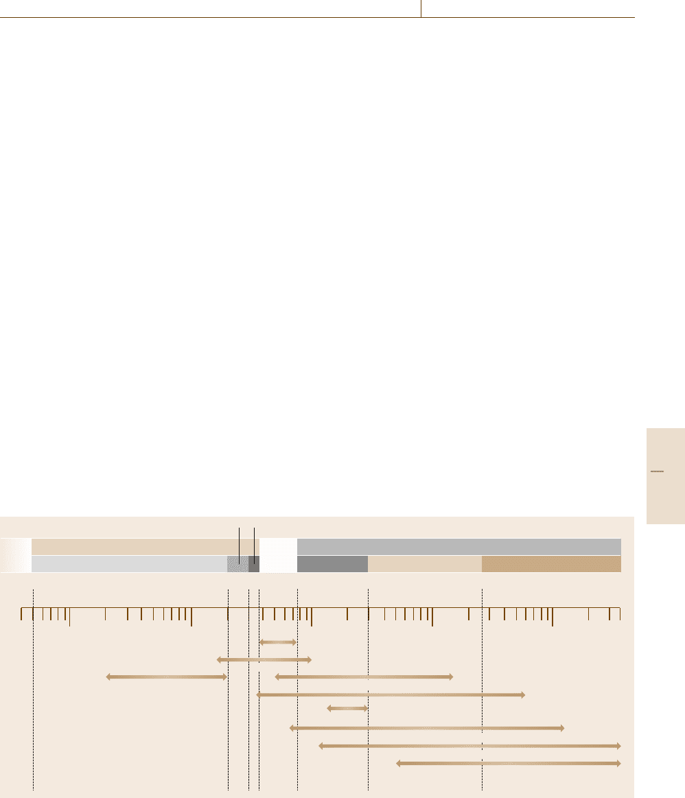
Fig. 11.4 Wavelength regions of various wavelength-selection elements and devices
the specific detectivity D
∗
, where NEP = PV
n
/V
s
and
D
∗
=
√
AΔ f /NEP, where P is the radiation flux, V
s
is the output signal, V
n
is the root mean squared value
of output noise, A is area of the detector, and Δ f is
the noise-equivalent frequency bandwidth. The time re-
sponse is represented by a step response or a steady-state
frequency response. The step response is represented by
a rise time or a fall time, which are used especially for
detectors with a nonlinear response. For high-speed de-
tectors, the time constant is important; this is calculated
by the internal resistance of the detector and the parallel
output capacitance. Impedance matching with the fol-
lowing electronics is also important.
11.1.3 Wavelength Selection
In a practical measurement, it is often necessary to select
a suitable wavelength from the light source. This section
deals with some wavelength-selection techniques [11.1–
4]. In order to select the monochromatic or quasi-
monochromatic light, we usually use a dispersion ele-
ment, such as an optical filter, a prism, and a diffraction
grating. Generally, the diffraction grating is installed
in a monochromator (MON). To gather all spectral in-
formation simultaneously, one uses a polychromator
(POL) in combination with a multichannnel detector
Part C 11.1
Optical Properties 11.1 Fundamentals of Optical Spectroscopy 593
(MD). In the IR region, a Michelson-type interferom-
eter is sometimes used for a Fourier-transform spec-
trometer (FTS) [11.15]. For extremely high spectral-
resolution measurements, a Fabry–Pérot interferometer
should be considered. [11.16] Figure 11.4 shows various
elements, devices, systems applicable in each wave-
length region.
The prism has been used as the main dispersion
element. Dispersion occurs in the prism primarily be-
cause of the wavelength dependence of the refractive
index of the prism material. Many materials for the
prism have been used, for example, glass (350 nm–
1 μm), quartz (185 nm–2.7 μm), CaF (125 nm–9 μm),
NaCl (200 nm–17 μm), KCl (380 nm–21 μm). When
the wavelength is λ (or λ +Δλ)andtheanglebe-
tween the incident beam and the deviated monochro-
matic ray is θ (or θ +Δθ), the angular dispersion,
Δθ/Δλ,isgivenbyΔθ/Δλ = Δθ/Δn ·Δn/Δλ =
2 sin
(
α/2
)
/
1−n
2
sin
2
(
α/2
)
Δn/Δλ, where n and α
are the refractive index and the apex angle of the prism,
respectively. In order to increase the spectral resolution,
λ/Δλ, we should use a prism with a long base L because
λ/Δλ = L ·
(
Δn/Δλ
)
.
A plane diffraction grating is made by ruling par-
allel closely spaced grooves on a thin metal layer de-
posited on glass. When collimated light flux strikes the
grating in a plane perpendicular to the direction of the
grooves, different wavelengths are diffracted and con-
structively interfere at different angles. Although there
are two types of gratings, transmission and reflection, the
reflection type is invariably used for wavelength selec-
tion. If the incident angle is α and the diffraction angle
is β, measured from the normal to the grating plane, and
the groove interval is d, the following grating formula
holds, d(sin α +sin β) =mλ, where m is the order of
diffraction. In the formula, the order m as well as the
diffraction angle β is taken as positive for diffraction
on the same side of the grating normal as the incident
ray and negative on the opposite side. Then, the angu-
lar dispersion is given by Δβ/Δλ = m/
(
d cos β
)
and
the resolution power is given by λ/Δλ =mN, where N
is the total number of grooves. From the formula, we
can understand that many wavelengths are observed for
a specified diffraction angle β for a given α and d.
This phenomenon is known as overlapping orders. From
the following two equations, d(sin α +sin β)
= mλ =
(m +1)(λ −Δλ), we can obtain Δλ =λ/ (m +1);the
value Δλ is called the free spectral range. The over-
lapping orders are usually separated by limiting the
source bandwidth with a broadband filter, called the or-
der sorter, or with a predisperser.
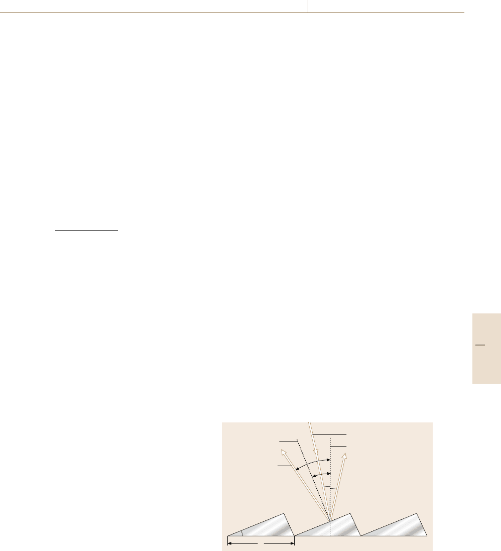
Figure 11.5 shows a typical shape of the cross section
of the groove. When the angle between the grating plane
and the long side of the grooveis γ so that γ −α =β −γ,
the incident and the diffracted light satisfy the relation
for specular reflection on the long side of the triangle.
Then, we obtain the relation 2d sin γ cos
(
α −γ
)
=mλ.
When, we put α =β =γ and m=1,then2d sin γ = λ.
Such a wavelength λ and angle γ are called the blaze
wavelength and angle, respectively. The blazed grating is
often called an echellete. In this situation, the maximum
diffraction efficiency is obtained. For high-resolution
spectral measurements, an echelle grating is used, which
is a relatively coarse grating with large blaze angles. The
steep side of the groove is employed at very high orders.
A concave grating is the same as a plane grating
but the grooves are ruled on a concave mirror so that
the grooves become a series of equally spaced straight
lines when projected onto a plane perpendicular to the
straight line connecting the center of the concave shape
and a center of its curvature. A circle, whose diam-
eter is equal to the radius of the curvature and which
is on a plane perpendicular to the grooves, is called
the Rowland circle. Rays starting from a point on the
Rowland circle and diffracted by the grating are focused
onto a point on the same circle. The two points form an
optical conjugate pair with respect to each other. Usu-
ally, an entrance and an exit slit are placed on the two
points. A problem concerning the concave grating is the
presence of relatively large astigmatism. It is, however,
used for the UV region because no additional reflec-
tion optical element that introduces reflection energy
loss is necessary. Recently, various kinds of holographic
gratings have been developed to solve the problem of
aberration, including astigmatism.
d
Groove normal
Incident ray
Grating normal
0-th order
Diffracted ray
(m =1)
α
η
β
β
η
Fig. 11.5 Cross section of a blazed grating. By tilting the
groove facet by an angle γ , the zeroth-order ray does not
correspond to the specularly reflected ray from the groove
surface
Part C 11.1

594 Part C Materials Properties Measurement
When choosing a wavelength-selection method, sig-
nificant parameters to be considered are the dispersion
characteristics, resolution power, solid angle and F-
number (or optical throughput factors), degree of stray
light, and optical aberration. One of the most convenient
and simplest ways is to use a spectroscopic filter such
as a color glass filter or an interference filter. However,
those lack versatility. The MON is a multipurpose ap-
paratus, which has a grating, an entrance, an exit slit,
additional optics, and a wavelength-selection mecha-
nism in one box, by which monochromatic light can
be extracted. Many types of mounting and optical ar-
rangement of the optics including the grating, have been
proposed.
Although the dispersion-type MON is widely used
for the purpose of wavelength selection, it has some
drawbacks. In principle, its optical throughput is not
large because of the presence of the entrance slit. Fur-
thermore, because of the requirement of the wavelength-
scanning mechanism for measuring a continuum spec-
trum, the total number of wavelength elements limits the
signal-gathering time allocatable to a unit wavelength
element, resulting in lowering signal-to-noise (SNR) ra-
tio. On the contrary, the FTS has optical throughput and
multiplex advantages over the dispersion-type MON.
This is because the FTS requires no entrance slit and
the entire spectrum is measured simultaneously in the
form of an interferogram. However, the multiplex advan-
tage is given only when the detector noise is dominant,
such as for an IR detector. Nevertheless, it is some-
times used in the visible region. This is because of the
presence of the optical throughput advantage, high pre-
cision in wavenumber, and the possibility of realizing
extremely high spectral resolution. However, even for
the dispersion-type MON,whenusedinaformofaPOL
together with the MD, the multichannel advantage is
generated. Table 11.2 summarizes the SNR of the FTS,
(SNR)
FTS
, and that of the POL with an MD,(SNR)
POL
,
over that of the dispersion MON with a single detector,
(SNR)
MON
, for cases of when the detector noise, the shot
Table 11.2 Comparisons of the SNR of the FTS,(SNR)
FTS
, and that of the POL with a MD,(SNR)
POL
,overthatofthe
MON with a SD,(SNR)
MON
, for cases when the detector noise, the shot noise, and the scintillation noise are dominant,
where n is the total number of spectral elements
Noise Detector noise Shot noise Scintillation noise
SNR
(
SNR
)
FTS
(
SNR
)
MON
√
n
2
1
√
2
1
n
(
SNR
)
POL
(
SNR
)
MON
√
n
√
n 1
noise, and the scintillation noise is dominant. In the ta-
ble, n is the total number of spectral elements.
11.1.4 Reflection and Absorption
Reflection or absorption spectra provide rich infor-
mation on the energy levels of the material, such as
inner or valence electrons, vibrations or rotations of
molecules or defects in condensed matters, a variety of
energy gaps and elementary excitations, e.g. phonons
and excitons.
Reflection and Transmission
When a light beam incident on a material surface passes
through the material, some of the light is reflected at the
surface, while the rest propagates through the mater-
ial. During the propagation the light is attenuated due
to absorption or scattering. The coefficients of reflec-
tivity R and transmittance T are defined as the ratio
of the reflected to the incident power and the trans-
mitted to the incident power, respectively. If there is
no absorption or scattering, R +T = 1. A schematic
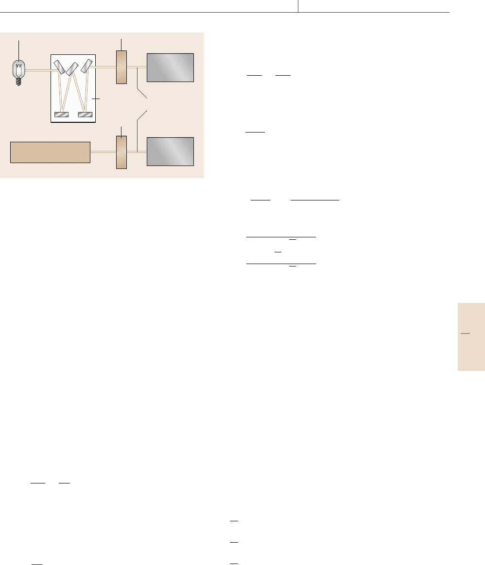
diagram for measuring R or T is shown in Fig. 11.6.
A tunable light source, a combination of a white
light (Sect. 11.1.1) and a monochromator (Sect. 11.1.3)
or a tunable laser (Sect. 11.1.5), is used here. Details
of detectors are reviewed in Sect. 11.1.2. Changing the
wavelength λ of the tunable light source, one can obtain
a reflectivity spectrum R(λ) or a transmittance spectrum
T(λ). For convenience the white light directly irradi-
ates the sample and the reflected or transmitted light is
detected with a combination of a spectrometer and an
array detector, e.g. CCD, if the luminescence from the
sample caused by the white light is negligible.
If the beam propagates in the x direction, the inten-
sity I(x) at position x satisfies the following relation
ΔI(x) = I(x + dx) −I(x) =−αI(x)dx ,
∴
dI(x)
dx
=−αI .
Part C 11.1
Optical Properties 11.1 Fundamentals of Optical Spectroscopy 595
White
light
Sample
Detector
Detector
Transmission
or reflection
Mono-
chromator
Sample
Tunable laser
Fig. 11.6 Schematic diagram of reflection or transmission
measurement
Here α is called the absorption coefficient. The inte-
grated form is
I(x) = I
0
exp(−αx) , (11.1)
where I
0
is the intensity of the incident light. The posi-
tion at x = 0 corresponds to the surface of the material.
This relation is called Beer’s law. If the scattering is neg-
ligible, the transmittance T is described by
T = (1 −R
1
)exp(−αl)(1 − R
2
) , (11.2)
where R
1
and R
2
are the reflectivities of the front and
back surfaces, respectively, and l is the sample thickness.
Optical Constants
If the light propagates in the x direction, the electric field
is described by
E(x, t) = E
0
exp [i
(
kx −ωt
)
] , (11.3)
where k is the wavevector of the light and ω is an an-
gular frequency. In a transparent material with refractive
index n, k and the wavelength in vacuo λ are related each
other through
k =
2π
λ/n
=
nω
c
. (11.4)
This formula can be generalized to the case of an ab-
sorbing material by introducing the complex refractive
index [11.17]
˜
n = n +iκ, (11.5)
k =
˜
nω
c
,
(11.6)
where κ is called the extinction coefficient. The imagi-
nary part of
˜
n leadsto an exponentialdecay of the electric
field; the absorption coefficient can be described by
α =
2κω
c
=
4πκ
λ
. (11.7)
The amplitude reflectivity r, the ratio of the electric field
of the incident light to that of the reflected light, in the
case of normal incidence is described by [11.18]
r =
˜
n −1
˜
n +1
. (11.8)
If we define the real and imaginary part of r by
r ≡ R exp(iθ) , (11.9)
then the (intensity) reflectivity can be described by
R =
˜
n −1
˜
n +1
2
=
(n −1)
2
+κ
2
(n +1)
2
+κ
2
, (11.10)
and conversely, n and k are written as
n =
1 −R
1+R −2
√
R cos θ
, (11.11)
κ =
2
√
R sin θ
1+R −2
√
R cos θ
. (11.12)
Ellipsometry enables us to obtain the amplitude reflectiv-
ity [11.19]. Thus one can obtain the complex refractive
index by measuring the reflectivity.
The optical response of the material, e.g. light prop-
agation described in the complex refractive index, origi-
nates from the polarization induced by the incident light.
If the electric field E of the light is weak and within linear
regime (cf. Sect. 11.4), the polarization P is given by
P = ε
0
χ E , (11.13)
where ε
0
and χ are the vacuum dielectric constant and
the electric susceptibility, respectively. The electric dis-
placement is
D =ε
0
E +P ,
≡ε
0
εE . (11.14)
where ε is the complex dielectric constant;
ε =ε
0
(1 +χ) , (11.15)
=ε
1
+iε
2
, (11.16)
where ε
1
and ε
2
are the real and imaginary parts of ε.
From the Maxwell equation [11.1],
ε
ε
0
=
˜
n
2
,
ε
1
ε
0
=n
2
−κ
2
, (11.17)
ε
2
ε
0
=2nκ, (11.18)
Part C 11.1

596 Part C Materials Properties Measurement
and conversely,
n =
ε
1
+
ε
2
1
+ε
2
2
2
, (11.19)
κ =
−ε
1
+
ε
2
1
+ε
2
2
2
. (11.20)
Kramers–Kronig Relations
The Kramers–Kronig relations allow us to find the real
(imaginary) part of the response function of a linear pas-
sive system, if one knows the imaginary (real) part at
all frequencies. The relations are derived from the prin-
ciple of causality [11.17]. In the case of the complex
refractive index, the relations are written as
n(ω) =1+
2
π
P
∞
0
ω
κ(ω
)
ω
2
−ω
2
dω
, (11.21)
κ(ω) =−
2
πω
P
∞
0
ω
2
[n(ω
) −1]
ω
2
−ω
2
dω
, (11.22)
where P indicates the Cauchy principal value of the in-
tegral. Using these relations one can calculate n from κ,
and vice versa. The θ in (11.9) is calculated from the
reflectivity R using the following formula
θ(ω) =−
ω
π
P
∞
0
ln
R(ω
)
R(ω)
ω
2
−ω
2
dω
, (11.23)
thus n and κ are determined using (11.11, 11.12) from
the reflectivity spectrum. This analysis is very useful for
materials with strong absorption in which only the re-
flectivity is measurable. The Kramers–Kronig analysis
of reflection spectra with synchrotron radiation, which
covers extremely wide wavelength regions from the far-
IR to x-rays, reveals the electronic structures of a huge
number of materials [11.20].
The Lorentz Oscillator Model
(Optical Response of Insulators)
The responses of bound (valence) electrons in insulators
can be written by the equation of motion of a damped
harmonic oscillator
m
d
2
x
dt
2
=−mγ
dx
dt
−mω
2
0
x
−eE
0
exp(−iωt) , (11.24)
where m and e are the mass and charge of the electron,
γ is the damping constant, ω
0
is the resonant frequency,
E
0
is the amplitude of the electric field of the light. If
we assume x(t) = x
0
exp(−iωt),
x
0
=
−eE
0
m
ω
2
0
−ω
2
−iγω
. (11.25)
Thus the polarization is given by
P
resonant
=
ne
2
m
ω
2
0
−ω
2
−iγω
, (11.26)
where n is the number of electrons per unit volume.
Now we can write the electric displacement
D =ε
0
E +P
background
+ P
resonant
,
=ε
0
E +ε
0
χ
background
E +P
resonant
,
where the electric susceptibility χ
background
accounts
for all other contributions to the polarization. Us-
ing (11.15, 16), we obtain the following equations
ε(ω) =1+χ +
ne
2
ε
0
m
ω
2
0
−ω
2
−iγω
, (11.27)
ε
1
(ω) =1 +χ +
ne
2
ω
2
0
−ω
2
ε
0
m
ω
2
0
−ω
2
2
+(γω)
2
,
(11.28)
ε
2
(ω) =n
e
2
γω
ε
0
m
ω
2
0
−ω
2
2
+(γω)
2
. (11.29)
The dielectric constants in the low and high frequency
limit are defined as
ε(0) ≡ ε
ST
,ε(∞) ≡ε
∞
.
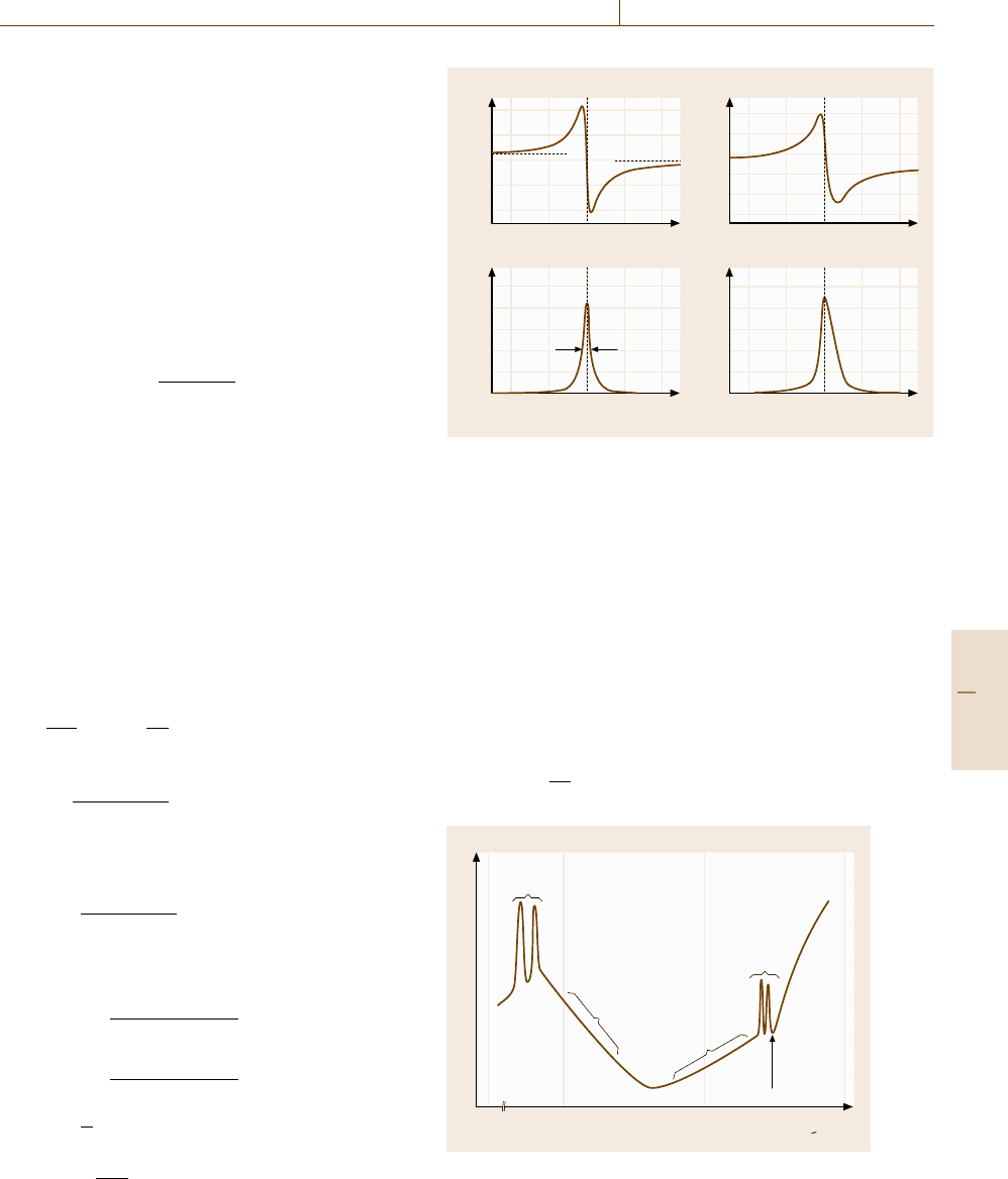
Figure 11.7 shows the frequency dependence of the op-
tical constants introduced in this section.
Typical Absorption Spectrum of Insulators
A schematic plot of a typical absorption spectrum of
insulators is shown in Fig. 11.8. There are sharp ab-
sorption lines due to phonons in the far-infrared region
and due to excitons in the visible or ultraviolet region;
a phonon is a quantized lattice vibration and an exciton
is a bound state of an electron and hole like a hydrogen
atom. The shape of the absorption or reflection spec-
tra of phonons or excitons can be analyzed by using the
Lorentz oscillator model. If the coupling between the
photon and the phonon (exciton) is strong, we have to
introduce a coupled mode of a photon and a phonon (ex-
citon), phonon–polariton (exciton–polariton) [11.21].
Phonon sidebands usually accompany the exciton ab-
sorption lines and provide information on the phonons
and excitons [11.22].
Part C 11.1
Optical Properties 11.1 Fundamentals of Optical Spectroscopy 597
Above the exciton lines, strong interband absorption
is observed. The absorption edge is caused by the onset
of the interband transition, in which free electrons and
free holes are created simultaneously across the band gap
of the insulator. We can obtain a variety of information
on the band structure of the material from the interband
absorption spectra. Between the phonon and exciton
lines there are two weak bands: the multiphonon absorp-
tion band due to the combination of several phonons
lies around the mid-infrared region and the Urbach tail
appears as the onset of optical absorption in the near-
infrared or visible region at finite temperature. The shape
of the Urbach tail is expressed as [11.21]
α(ω) ∝exp
−σ
(ω
0
−ω)
k
B
T
, (ω<ω
0
) , (11.30)
where σ is an empirical steepness parameter. The σ
indicates the strength of the exciton–phonon coupling,
because the Urbach tail is caused by phonon-assisted
processes. Generally, there is a minimum in the absorp-
tion coefficient between the multiphonon region and the
Urbach tail. In the case of SiO
2
glasses this minimum
lies in the near-infrared region around 1 eV. Thus optical
fibers operate between 1.2–1.6 μm (Sect. 11.1.5).
Drude Model (Optical Response in Metals)
The responses of free electrons in metals can be writ-
ten by the equation of motion (11.24) without a restoring
force
m
d
2
x
dt
2
=−mγ
dx
dt
−eE
0
exp(−iωt) . (11.31)
If we assume x(t) = x
0
exp(iωt) ,
x
0
=
eE
0
m(ω
2
+iγω)
. (11.32)
Thus the polarization is given by
P =−nex ,
=
−ne
2
E
m(ω
2
+iγω)
. (11.33)
D =ε
0
E + P
≡ε
0
εE ,
∴ ε = 1 −
ne
2
ε
0
m
ω
2
+iω/τ
=1 −
ω
2
p
ε
0
m
ω
2
+iω/τ
. (11.34)
τ ≡
1
γ
,
ω
p
=
ne
2
ε
0
m
1/2
, (11.35)
a) b)
30
10
–10
40
20
0
14060 12010080 14060 12010080
14060 12010080 14060 12010080
6
4
2
4
2
0
ω (THz) ω (THz)
ω (THz) ω (THz)
n
k
ε
1
ε
2
γ
Fig. 11.7 (a) Frequency dependence of the real and imaginary parts
of the dielectric constant, and (b) frequency dependence of the
complex refractive index, calculated in the case of ω
0
= 100 THz,
γ = 5THz,ε
ST
=12 and ε
∞
=10 using (11.28, 29)
where τ is the relaxation time and ω
p
is called the plasma
frequency. Figure 11.9 shows the reflectivity R in the
case of γ =0 using (11.10). Perfect reflection occurs for
ω ≤ ω
p
,andthenR decreases for ω>ω
p
, approaching
zero.
Electric conductivity can be generalized to the op-
tical frequency region. The current density j is related
to the velocity of free electrons and the electric field
through
j ≡−Ne
dx
dt
=σ E , (11.36)
Phonon
absorption
Multi
phonon
absorption
band
Exciton
absorption
Urbach
tail
Absorption
edge
0.01 1.0 10.00.10
log α (ω)
hω (eV)
Fig. 11.8 Schematic illustration of the absorption spectrum
of insulators
Part C 11.1