Czichos H., Saito T., Smith L.E. (Eds.) Handbook of Metrology and Testing
Подождите немного. Документ загружается.

618 Part C Materials Properties Measurement
Four-wave mixing (FWM) is a general name for the
third-order nonlinear optical processes and has a number
of variations. Its spectroscopic application is introduced
in Sect. 11.4.4.
11.4.2 Ultrafast Pulsed Laser
Properties of Ultrashort Pulses [11.51]
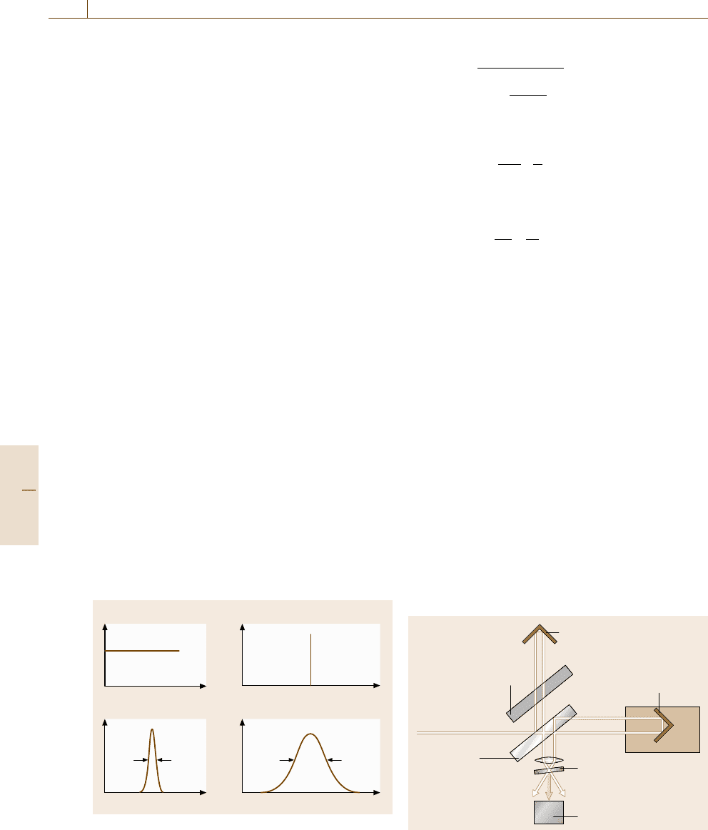
The relationship between a temporal profile (envelope of
the electric power |E(t)|
2
) and a spectral shape is illus-
trated in Fig. 11.41.ACW laser, in particular a single-
mode laser, delivers monochromatic light and the enve-
lope is independent of time, as shown in Fig. 11.41a. On
the other hand, a pulsed laser produces a pulsed light
which consists of a number of frequency components;
the pulse duration Δt and spectral width Δν are finite
in Fig. 11.41b. The relation between them is determined
by the Fourier transformation
ΔνΔt ≥ K , (11.105)
where K is a constant determined by the pulse shape
function, as shown in Table 11.9. The equal sign is
valid only for pulses without frequency modulation and
such pulses are called Fourier-transform-limited. This
inequality corresponds to the uncertainty relation be-
tween energy and time in quantum mechanics.
The temporal shape of the utrashort pulses with very
broad spectral width is easily distorted by group velocity
dispersion,dv
g
/dω [11.51], where v
g
is a group veloc-
ity; the red component propagates through the material
normally faster than the blue component. If the original
pulse envelope is described by a Gaussian exp(−t
2
/τ
2
0
),
a)
b)
CW laser
Pulsed laser
t
t
v
ΔvΔt
v
Fig. 11.41a,b Relationship between temporal profile and
spectral shape
the pulse width broadens as
τ =τ
0
1+
|GDD|
τ
2
0
2
, (11.106)
where the group delay dispersion (GDD) is written as
GDD(ω) =l
d
2
dω
2
ω
c
n(ω)
, (11.107)
where l is the sample length. The GDD is related to the
group velocity dispersion as follows
GDD(ω) =
d
dω
l
v
g
. (11.108)
The compensation of the pulse broadening in (11.106)is
crucial when dealing with ultrashort pulses.
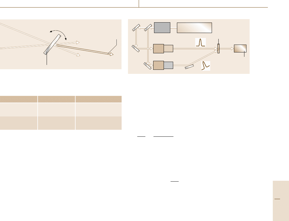
The time width of the ultrashort pulses is determined
by an auto-correlator in Fig. 11.42. The incoming pulse
is divided in a beam splitter; a part of the light passes
through a fixed delay line, while the other part passes
through a variable delay line. They overlap on the non-
linear crystal surface and SHG occurs. The intensity of
the SH light with respect to the time delay τ corresponds
to the autocorrelation function I
A
(τ) of the input pulse
I(t) as follows
I
A
(τ) =
∫
I(t)I(t −τ)dt . (11.109)
The pulse width of the input pulse I(t) is estimated
from the width of the autocorrelation function I
A
(τ)us-
ing Table 11.9, if the pulse shape function is known (or
assumed).
Q-Switching
A Q-switch, which controls the Q value of a cavity, pro-
vides a short and very intense laser pulse. The Q value
Fixed delay
Variable delay
Compensation plate
Input
Beam splitter
SHG crystal
Detector
Fig. 11.42 Set-up of auto-correlator
Part C 11.4

Optical Properties 11.4 Nonlinear Optics and Ultrashort Pulsed Laser Application 619
Table 11.9 Calculated results of K, the relation between Δt, τ
A
which is the width of the autocorrelation function for
typical functions
Pulse shape function K Δt/T τ
A
/T Δt/τ
A
Gaussian: exp(−t
2
/T
2
) 0.441 2
√
ln 2 2
√
2ln2 0.707
Diffraction function: sin c
2
(t/T ) 0.886 2.78 3.71 0.751
Hyerbolic square: sech
2
(t/T ) 0.315 1.76 2.72 0.648
Lorentzian: [1 +(t/T )
2
]
−1
0.221 2 4 0.500
One-sided exponential: exp(−t/T )(T > 0) 0.110 ln 2 2ln2 0.500
is a measure of how much light from the laser medium
is fed back into itself by the cavity resonator. A high
Q value corresponds to low resonator losses per round
trip. A schematic description of Q-switching is illus-
trated in Fig. 11.43. Without a Q-switch, the laser de-
livers pulses with a moderate intensity and pulse width,
shown in Fig. 11.43a, according to the pumping condi-
tion, e.g. optical pumping with a flash lamp. With the
Q-switch (off), initially the laser medium is pumped,
while the Q-switch, producing the resonator with low
Q, prevents feedback of light into the medium as shown
in Fig. 11.43b. This produces population inversion; the
amount of energy stored in the laser medium will in-
crease, and finally reach some maximum level, as shown
in Fig. 11.44, due to losses from spontaneous emis-
sion and other processes. At this point, the Q-switch is
quickly changed from low to high Q, allowing feedback
a)
b)
c)
Without Q-switch
With Q-switch (low Q)
With Q-switch (high Q)
Laser medium
Total reflector Output coupler
Q-switch
off
Q-switch
on
Pump
Oscillation
Oscillation
Fig. 11.43a–c Schematic illustration of Q-switching
and the process of optical amplification by stimulated
emission to begin, as shown in Fig. 11.43c. Because of
the large amount of energy already stored in the laser
medium, the intensity of light builds up very quickly; this
also causes the energy stored in the medium to be ex-
hausted quickly, as seen in Fig. 11.44. The net result is
a short pulse with a width of 1–100 ns, which may have
a very high peak intensity. The typical example is a Q-
switched Nd:YAG laser, which can deliver 1 MW.
Mode-Locking
If all modes shown in Fig. 11.15 operate with fixed
phases among them, the laser output in a simple case
is described by
E
(
t
)
=
N
m=−N
E
0
exp[i(ω
0
+mΔω)t +mθ
0
],
= E
0
sin[(2N +1)(Δωt +θ
0
)/2]
sin[(Δωt +θ
0
)/2]
exp(iω
0
t) ,
(11.110)
where ω
0
is the center frequency of the laser spectrum,
Δω = π(c/l) from (11.60) and we assume that 2N +1
modes with the same amplitude E
0
exist and that the
phase difference between adjacent modes is constant θ
0
.
Cavity loss
Cavity loss Cavity gain
Output intensity
Cavity gain
Time
100 %
0%
Fig. 11.44 Time evolution of cavity loss caused by the Q-
switch, optical gain due to the pumping and laser intensity
Part C 11.4
620 Part C Materials Properties Measurement
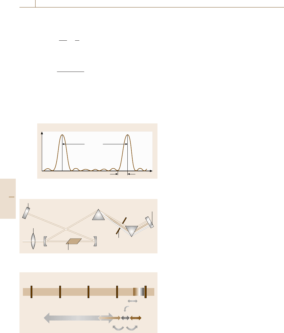
The calculated envelope |E(t)|
2
is plotted in Fig. 11.45.
The time interval between the strong peaks Δt is
Δt =
2π
Δω
=
2l
c
, (11.111)
which corresponds to the round-trip time of the laser
pulse inside the cavity. The pulse width of the peak δt is
δt =
2π
(2N +1)Δω
. (11.112)
This means that a broader spectral width results in
a shorter pulse width, as expected from the energy–time
uncertainty relation.
Mode-locking is achieved by modulation of the res-
onator loss synchronized to the round-trip time of the
t
E
2
(t)
δt
Δt = 2l/c
Fig. 11.45 A temporal profile of |E(t)|
2
in the case N = 7
in (11.105)
Output coupler
End-mirror
Aperture
Pump lens
Ti:sapphire
Fig. 11.46 Schematic construction of a mode-locked Ti:sapphire
laser
3 mm 300 nm300 μm30μm3μm
10
11
10
12
10
13
10
14
10
15
Far-IR Mid-IR Near-IR Visible
Frequency (Hz)
OR
Ti:sapphire
DFG SHGOPA
Fig. 11.47 Frequency map covered by the OPA system
laser pulse. There are two types: active mode-locking
and passive mode-locking. The former uses an AOM
which acts as a shutter that is open during a certain
duration separated by the round-trip time; a typical
example is a mode-locked Nd:YAG laser. The most
successful method for the passive mode-locking is Kerr-
lens mode-locking (KLM), which manifests itself in
a mode-locked Ti:sapphire laser. KLM is based on the
optical Kerr effect of the laser medium, Ti:sapphire
itself.
Figure 11.46 shows a schematic configuration of
a Ti:sapphire laser. An intense pulse which experiences
large refractive index due to the n
2
is focused within the
Ti:sapphire rod, so the diameter of the pulse is reduced.
Only the intense pulse can pass through the aperture
inside the cavity with less loss and be amplified fur-
ther. The very broad gain spectrum of the Ti:sapphire
crystal allows the formation of ultrashort pulses with
10-fs duration. The group velocity dispersion is com-
pensated with the prism pair, which introduces different
delays for the different frequency components. The rep-
etition rate of the mode-locked lasers is determined
by the cavity length, typically 80 MHz. Generation of
more intense pulses is possible by reducing the rep-
etition rate; a regenerative amplifier delivers intense
pulses with energy of ≈ 1 mJ and repetition frequency
of ≈ 1 kHz [11.51]. Such pulses bring a variety of
nonlinear phenomena; an optical parametric amplifier
(OPA) which utilizes parametric process in Sect. 11.4.1
boosts a seed light of white-light continuum and works
as a tunable light source. Thus the OPA system with
additional frequency converters in Fig. 11.47 pumped
with a regenerative amplifier based on a Ti:sapphire os-
cillator provides tunable light pulses with fs duration
from the far-IR to UV region. This is a powerful tool
for time-resolved and/or nonlinear spectroscopy.
11.4.3 Time-Resolved Spectroscopy
Time-resolved spectroscopy enables us to obtain the
dynamics of electrons, phonons, spins, etc. in the ma-
terials in timescales down to femtoseconds. Pulsed
lasers introduced in the last section are usually uti-
lized as light sources, while many detection tech-
niques are used depending on the timescale or the
repetition rate of events. The techniques for time-
resolved spectroscopy are classified into electrical
methods with electronic apparatus and optical meth-
ods using nonlinear optics. Time-resolved measure-
ments for the luminescence are reviewed in this
section.
Part C 11.4
Optical Properties 11.4 Nonlinear Optics and Ultrashort Pulsed Laser Application 621
Electrical Methods
The electric signal from a photosensor, e.g. a PMT or
PD (Sect. 11.1.2), is registered with electrical apparatus
showninTable11.10 (except a streak camera). Their
principles are illustrated in Fig. 11.48.
1. A digital storage oscilloscope with sample rates
higher than 1 GS/s makes it possible to follow the
electric signal with a time resolution of nanosec-
onds [11.52].
2. A boxcar integrator stores the signal during a time
window whose position and duration (wider than ns)
can be set arbitrarily [11.52]. Though temporal pro-
files can be obtained by sweeping the time window,
this apparatus is mainly used for the gating of the
temporal signal with a low repetition rate of up to
1 kHz, e.g. in pump-probe experiments using a re-
generative amplifier (Sect. 11.4.4).
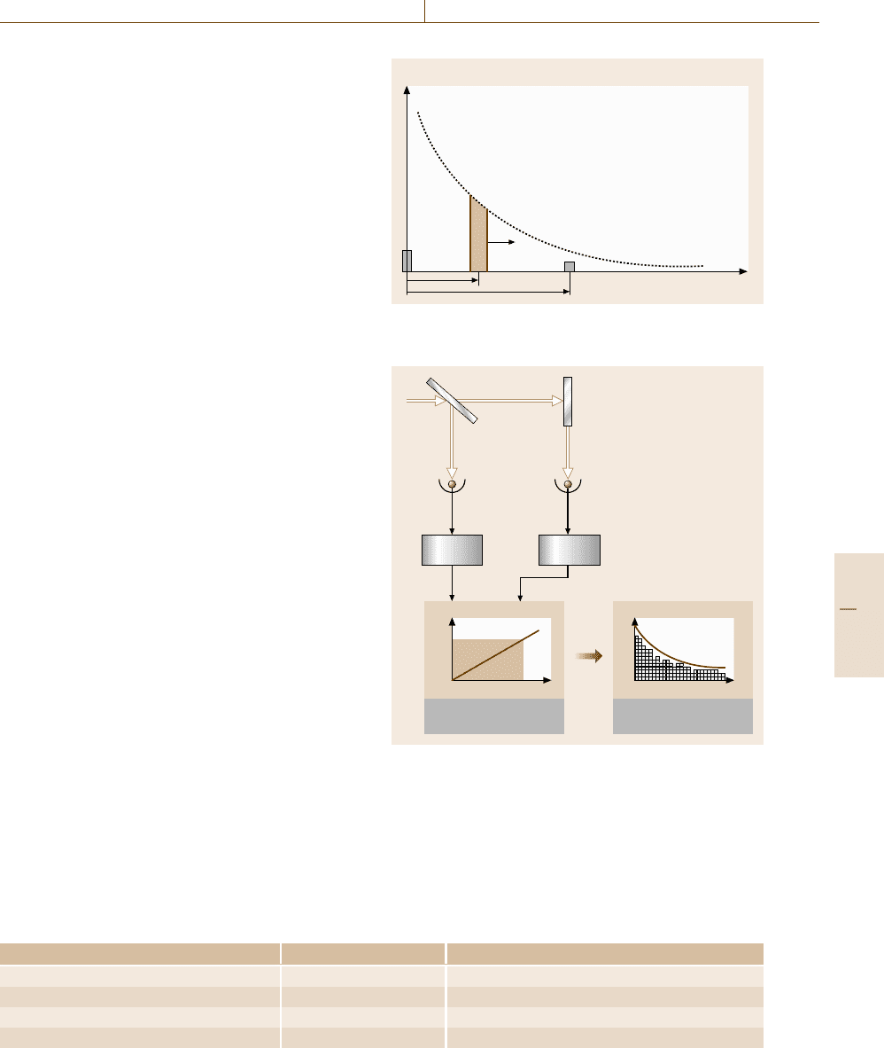
3. A time-to-amplitude converter (TAC) is used with
a multichannel analyzer (MCA) to perform time-
correlated single-photon counting (TCSPC).
A schematic diagram of the TCSPC method is de-
picted in Fig. 11.49. Here CFD is an abbreviation of con-
stant fraction discriminator which discriminates a signal
pulse from a noise as follows. The CFD produces an out-
put electric pulse when the input voltage exceeds a preset
threshold value; the time delay between the input and
output pulses does not depend on the input electric pulse
height or shape. Very weak light behaves as a photon,
which can be counted as an electric pulse from a PMT
or APD. The time interval between the excitation pulse
and the luminescence pulse from the sample reflects the
decay time statistically; the accumulation of a number
of such events reproduces the decay curve. The TAC
produces an electronic pulse with a height which is pro-
portional to the time difference between the start pulse
triggered by the excitation pulse and the stop pulse from
the detector. The MCA receivesthe electronic pulse from
the TAC and converts the voltage into a channel address
number of a storage memory. A histogram, which cor-
responds to the decay curve, is built up in the MCA
with increasing numbers of events. The counting rate
should be smaller than ≈ 1%, so that the probability
Table 11.10 Comparison between four electric methods
Apparatus Time resolution Features
Digital storage oscilloscope ≈ ns Single-shot or repetitive events
Boxcar integrator ≈ sub-ns Repetitive events
Time-to-amplitude converter (TAC) ≈10 ps Repetitive events, single photon counting
Streak camera ≈ ps Single-shot or repetitive events
Intensity
Time
1
2
3
Fig. 11.48 Illustration of the principles for detecting tran-
sient electric signals
Start
Stop
CFD CFD
Reference Luminescence
TAC MCA
ΔV
ΔVΔt
Fig. 11.49 Schematic diagram of the time-correlated
single-photon counting method
of a simultaneous arrival of two photons is negligible
(< 0.01%). Thus a light source with a high repetition
rate, e.g. a mode-locked laser, is required [11.53]. The
time resolution of this technique is determined by the jit-
Part C 11.4
622 Part C Materials Properties Measurement
μ
1
μ
2
μ
3
t
μ
Spectro-
meter
Incident light
Trigger signal
Sweep voltage generator
Photocathode Accelerating
electrode
Slit
Deflection
electrode
MCP Phosphor screen
Streak image
CCD
camera
Direction
of deflection
μ
1
μ
2
μ
3
μ
t
Fig. 11.50 Schematic construction of the streak camera
Polarizer (P2)
Signal
Polarizer (P1)
Gate Pulse
Optical Kerr media
Fig. 11.51 Schematic illustration of the Kerr shutter
ter of the electric circuit, not by the width of the electric
signal from the photosensors. Therefore, time resolution
of tens of picoseconds can be achieved with a specially
designed PMT or APD. Very accurate data can be ob-
tained because of no linearity problems in the detector,
but convolution analysis is usually required in sub-ns re-
gion, because an artifact, called after-pulse, due to the
photosensors distorts the signal.
A streak camera is widely used in time-resolved
spectroscopy, because it enables us to obtain temporal
and spectral information simultaneously. A schematic
construction of the streak camera is illustrated in Fig. 11.50.
A spectrometer is usually installed before the streak
camera in order to disperse the incoming light hor-
izontally. The spectrally dispersed light impinges on
a photocathode from which photoelectrons are emit-
ted. The electrons are accelerated and temporally dis-
persed by deflection electrodes subjected to a rapidly
changing sweep voltage in the vertical direction. Then
the spectrally and temporally dispersed electrons hit
a microchannel plate (MCP) which multiplies electrons
while keeping their spatial distribution. The multiplied
electrons irradiate a phosphor screen on which a so-
called streak image appears. The image is recorded
with a CCD camera. A time-resolved spectrum can
be obtained even for a single event, if the incident
light is strong. This feature enables us to study a phe-
nomenon which shows substantial shot-by-shot fluctu-
ations [11.54]. Time resolution of 200 fs is achieved in
single-shot detection. Usually repetitive events are inte-
grated on a CCD chip. In this case, the electronic jitter
of the trigger signal synchronized to the incident light
pulse determines the time resolution of the streak cam-
era. A synchroscan streak camera used for mode-locked
lasers with high repetition rates of ≈100 MHz achieves
picosecond time resolution [11.55]. In the case of very
weak light, single-photon counting detection is possible
using a fast-readout CCD camera, because the MCP has
a large multiplication factor.
Optical Methods (Using Nonlinear Optics)
Optical Kerr shutters (OKS) utilize the optical Kerr
effect (Sect. 11.4.1); a Kerr-active medium with large
χ
(3)
works as an optical gate. The schematic configu-
ration of the OKS is depicted in Fig. 11.51. A strong
laser pulse induces birefringence in the Kerr medium,
so that the plane of the polarization of the incident
light determined by a polarizer P1 is rotated. Thus
the incident light, normally blocked by a crossed po-
larizer P2, can pass through the P2. This configura-
tion is inserted between the collection lenses and the
spectrometer in Fig. 11.12. The time-resolved spec-
trum is then obtained by changing the delay between
the gate and incident pulses [11.56]. The extinction
ratio of the crossed polarizers determines the back-
ground of this technique, while the time response of
the Kerr medium determines the time resolution of
the OKS.
Part C 11.4
Optical Properties 11.4 Nonlinear Optics and Ultrashort Pulsed Laser Application 623
PhasematchingLuminescence φ
IR
Sum frequency
photons φ
S
Nonlinear
optical crystal
Gating laser
pulses φ
P
υ
Fig. 11.52 Principle of up-conversion spectroscopy
Table 11.11 Comparison between the Kerr shutter and up-
conversion
Method Time resolution Features
Kerr shutter sub-ps Strong gating pulse
is required
Up-conversion ≈100 fs Wavelength scanning
is required
Up-conversion spectroscopy is based on SFG
(Sect. 11.4.1); the up-converted photon ω
s
from IR
luminescence ω
IR
is emitted when the gating laser
pulse ω
p
irradiates the nonlinear crystal, as shown
in Fig. 11.52.A combination of the pump pulse and the
nonlinear crystal acts as an optical gate like a boxcar
integrator. By sweeping the delay time of the pump
pulse, a temporal profile of the luminescence is ob-
tained. A time-resolved spectrum is obtained by scan-
ning the crystal angle (and monochromator) for the
phase-matching condition [11.57]. Down-conversion for
UV luminescence is also possible.
11.4.4 Nonlinear Spectroscopy
Nonlinear spectroscopy reveals electronic structures, re-
laxation processes in various materials and provides us
rich information on the materials which cannot be sup-
plied by linear spectroscopy. Though the application of
nonlinear spectroscopy is very wide, this section fo-
cuses on the topics for time-resolved measurements.
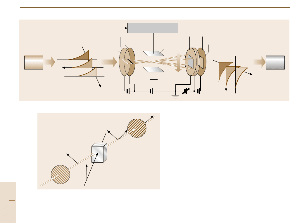
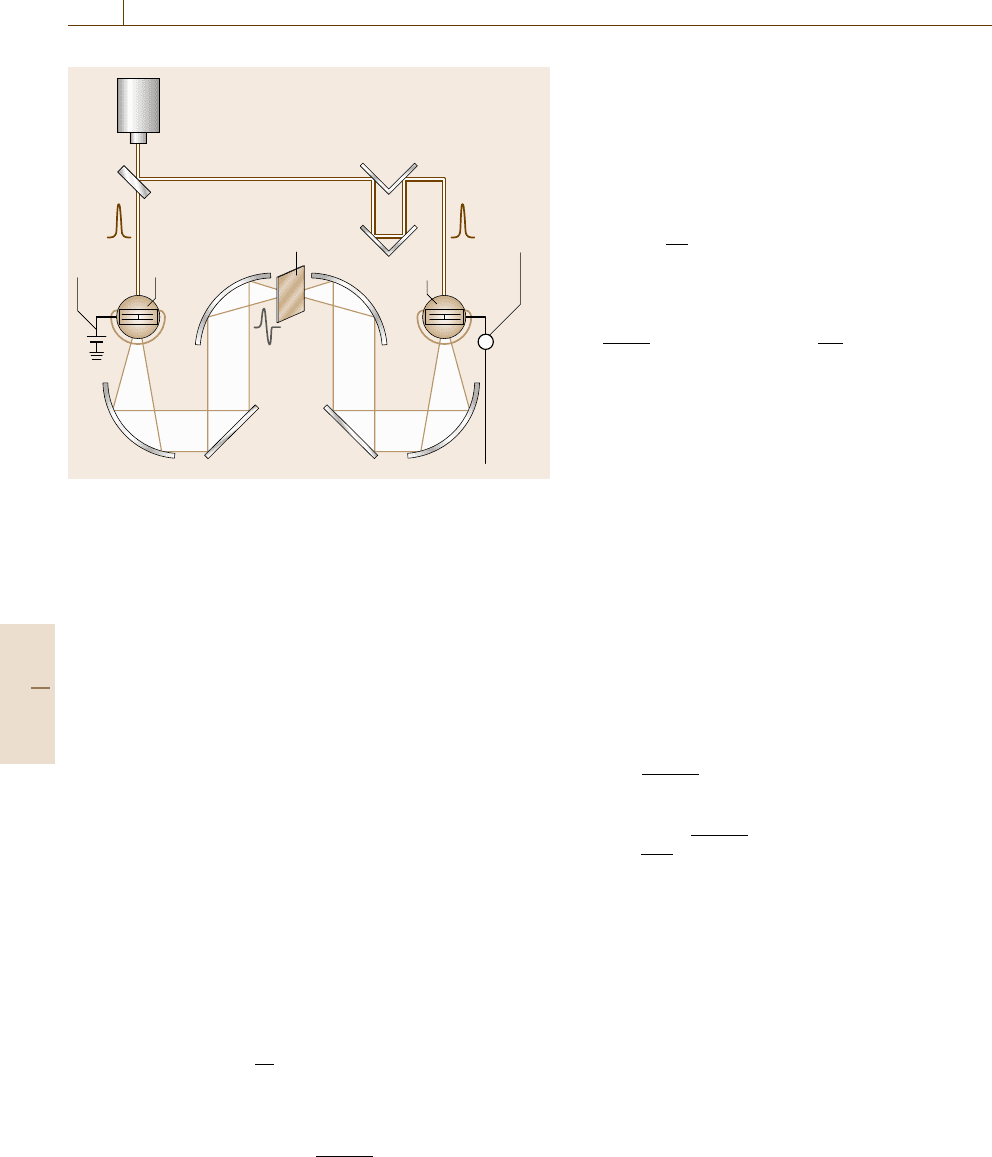
Pump-Probe Experiment
In the pump-probe experiment, a pump pulse causes the
absorption or reflection change of the material, which
is observed in a probe pulse. This technique enables us
to obtain a temporal evolution of an optical response
of the material with ultrafast time resolution (shorter
than 10 fs) by sweeping the time delay between pump
and probe pulses. A schematic experimental set-up is
showninFig.11.53. Two laser beams are focused on
the same spot of the sample. A delay line with vari-
Regen. ML Ti:sapphire
OPA
OPA
Probe
Pump
Sample
Detector
DFG
SHG
Fig. 11.53 Typical experimental set-up for the pump–probe
transmission measurement. ML: mode-locked laser; Re-
gen.: regenerative amplifier
able length is used to change the optical path difference
between pump and probe paths. In the case of transmis-
sion pump-probe measurement, differential transmis-
sion change is defined as
ΔT
T
=
I
on
−I
off
I
off
, (11.113)
where I
on
and I
off
are the intensities of the probe pulses
passing through the sample with and without the pump
pulse, respectively. Pump-induced absorption change
Δα is expressed by
Δαl =ln
1+
ΔT
T
, (11.114)
where l is the sample thickness.
By scanning the probe frequency the spectrum of the
absorption change can be obtained. A combination of
white-light continuum in Sect. 11.4.1, which is available
in the visible region, as a probe pulse and an array detec-
tor reduces the acquisition time remarkably. In this case,
the frequency chirp of the white-light continuum should
be corrected.
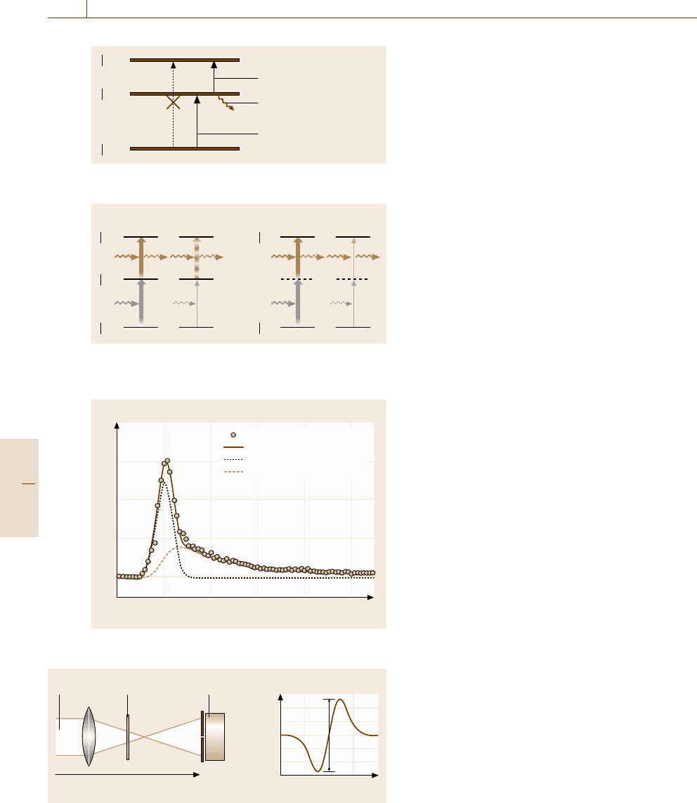
Transient Absorption
and Two-Photon Absorption
A schematic diagram for transient absorption is illus-
trated in Fig. 11.54. If nonradiative processes is domi-
nant and luminescence cannot be observed, the transient
absorption measurement provides decay process of the
excited state |e
1
. In addition, the higher excited state
|e
2
, which cannot be observedin the linear (one-photon)
absorption, may be found in the transient absorption.
Here materials with inversion symmetry have a selection
rule
g|r|e
1
= 0, e
1
|r|e
2
= 0, g|r|e
2
=0 , (11.115)
if |gand |e
2
are even, |e
1
is odd. Absorption decrease
called bleaching, corresponding to a negative signal of
Part C 11.4
624 Part C Materials Properties Measurement
e
2
>
e
1
>
g>
Transient absorption
Radiative or non-radiative
decay (rate: γ)
(Normal) absorption
Fig. 11.54 Schematic diagram for transient absorption
e
1
>
g> g>
e
2
> e
2
>
Transient absorption Two-photon absorption
Pump
Probe
Pump
Probe
Life-
time: 1/γ
Fig. 11.55 Comparison between transient absorption and
two-photon absorption
0.4
0.2
0
012
Delay time (ps)
Data
Pulse + decay
Pulse Δτ = 0.2ps
Convoluted decay τ = 1 ps
Δal
Fig. 11.56 Typical example of the absorption change
Laser Sample Detector
1.1
1.0
0.9
–5 50
T
z
z
ΔT
a) b)
Fig. 11.57 (a) Schematic illustration of Z-scan measurement, and
(b) normalized transmission against z
Δαl, shows population decrease in the ground state |g.
This signal reflects a process of ground-state recovery.
The transient absorption shows an exponential de-
cay profile, while two-photon absorption (TPA)inwhich
pump and probe pulses absorbed simultaneously results
in an instantaneous response following the temporal pro-
file of the pump pulse, as illustrated in Fig. 11.55. The
TPA reveals hidden electronic levels which are not de-
tectable in linear spectroscopy.
Example of Pump-Probe Measurement
A typical example of the absorption change is shown
in Fig. 11.56 [11.58]. The signal consists of two com-
ponents: a Gaussian pulse with 0.2-ps width which is
determined by the pulse duration of the laser and an
exponential decay with decay constant τ = 1 ps. The
former is caused by the TPA. Changing the pump and
probe frequencies, we can obtain a TPA spectrum di-
rectly [11.59]. The latter arises from the transient ab-
sorption from the excited state |e
1
to the higher excited
state |e
2
in Fig. 11.55. Its decay constant reflects the
decay time of the excited state |e
1
. It is noted that con-
volution analysis is required in this case in which the
decay time is comparable to the pulse duration. Here
we calculated a convolution of Gaussian shape with
0.2-ps width and a single exponential decay with a 1-
ps decay constant, shown in the figure by a broken
line.
Z-scan
This simple technique allows us to measure both the
sign and magnitude of the nonlinear refractive in-
dex n
2
. A schematic set-up is shown in Fig. 11.57.
A laser beam with a Gaussian spatial beam profile is
focused at z = 0 and the sample position is varied.
The intensity transmitted through the aperture is meas-
ured as a function of the sample position z shown
in Fig. 11.57b. Here the sample acts as a lens whose
focal length depends on the position z. Numerical cal-
culation shows [11.60]
ΔT ≈ 0.4ΔΦ, (11.116)
where (11.102) is used. Thus we can obtain n
2
directly.
Four-Wave Mixing
There are many variations of four-wave mixing (FWM)
with two or three beams, which have the same
frequency (degenerate) or different frequencies (nonde-
generate). This phenomenon is based on the interfer-
ence between several beams inside the material [11.61].
FWM spectroscopy generally provides information on
Part C 11.4
Optical Properties 11.4 Nonlinear Optics and Ultrashort Pulsed Laser Application 625
coherent processes in the excited states. This technique
is also used to estimate the value of χ
(3)
.
11.4.5 Terahertz Time-Domain Spectroscopy
As a unique application of ultrashort pulsed lasers, ter-
ahertz (THz) time-domain spectroscopy (TDS)isintro-
duced in this section. The THz region is located between
microwave radiation and infrared light. Due to the lack
of a suitable light source and detector, spectroscopy
in this region was difficult and tedious. After the de-
velopment of the mode-locked Ti:sapphire laser, THz
TDS is intensively applied to many materials, e.g. doped
semiconductors, superconductors, biomaterials [11.62].
The TDS enables us to obtain a waveform of the THz
electric field E(t) itself, not |E(t)|
2
as in conventional
spectroscopy. This provides us a lot of advantages, e.g.
simultaneous determination of real and imaginary parts
of the dielectric function.
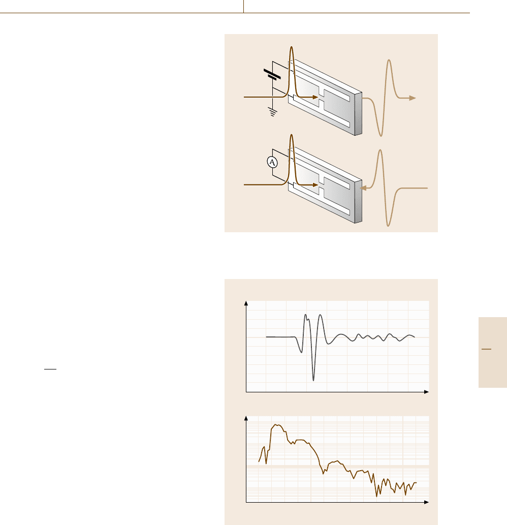
A schematic illustration of the generation and de-
tection method for a THz pulse using a photoconduc-
tive antenna is depicted in Fig. 11.58 [11.63]. The an-
tenna structure is fabricated on a substrate of semi-
insulating semiconductors, e.g. low-temperature grown
(LT)-GaAs. As an emitter, the antenna is subjected
to a DC voltage and irradiated with a femtosecond
laser around the gap between the dipoles, as illustrated
in Fig. 11.58a. Then the mono-cycle THz pulse E(t)is
emitted according to the simple formula
E(t) ∝
∂ j
e
∂t
, (11.117)
where j
e
is the surge current due to photocarriers cre-
ated by the irradiation of the laser pulse. Over 30 THz
generation has been reported by using 15-fs pulses.
The alternative method is OR (Sect. 11.4.1) of ultrashort
pulses; generation of ultra-broadband infrared pulse be-
yond 100 THz by using 10-fs pulses and GaSe crystals
has also been demonstrated [11.64].
The antenna is also used as a receiver; photocarriers
created by the pulse irradiation provide a transient cur-
rent j
d
(t) which is proportional to the instantaneous THz
electric field E(τ) as follows:
j
d
(t) ∝
E(τ)N(t −τ)dτ, (11.118)
where N(t) is the number of photocarriers created by the
laser pulse. If the pulse duration and the decay time of
the N(t) is negligibly short, N(t) = N
0
δ(t), then
j
d
(t) ∝ E(t) . (11.119)
Thus the THz electric field can be reproduced by sweep-
ing the time delay between the laser pulse and the THz
Gate pulse
THz pulse
a)
b)
Fig. 11.58a,b Schematic illustration of (a) the generation
and (b) the detection method for THz time-domian spec-
troscopy
10
5
0
–5
–10
–15
0 0.2 0.4 0.6 0.8
Time (ps)
10
3
10
2
10
1
10
0
0 20 40 60 80 100 120
a)
Intensity (arb. units)
Log intensity (arb. units)
Frequency (THz)
b)
Fig. 11.59 (a) Temporal waveform of ultra-broadband
THz radiation detected with a PC antenna. (b) Fourier-
transformed electric-field spectrum of (a)
pulse. Figure 11.59a shows a typical example of tempo-
ral waveform of the ultra-broadband THz emission by
OR with a 10-fs laser and a thin GaSe crystal detected
Part C 11.4
626 Part C Materials Properties Measurement
Signal
Femtosecond laser
Time delay
Sampling
pulse
Current
amplifier
Trans-
mitter
Receiver
DC
bias
THz pulse
Sample
A
Fig. 11.60 Experimental set-up for THz TDS
with a PC antenna [11.65]. Its Fourier-transformed spec-
trum is also shown in Fig. 11.59b. The high-frequency
region beyond 80 THz is detectable using a PC an-
tenna. The alternative method is to use electrooptic sam-
pling, which achieves ultra-broad-band detection be-
yond 120 THz [11.66].
An experimental set-up is shown in Fig. 11.60. Par-
abolic mirrors are used for focusing light in the far- and
mid-IR region.
The complex Fourier transformation of E(t)isde-
fined by
E(ω) =
1
2π
E(t) exp(−iωt)dt. (11.120)
In the transmission measurement, the complex refractive
index n can be obtained using
E(ω)
E
0
(ω)
=exp
−i[n(ω)−1]
Lω
c
, (11.121)
where L is the sample thickness and E(ω)andE
0
(ω) are
Fourier transformations of the transmitted and incident
waveform, respectively. Thus the real and imaginary
parts are determined simultaneously without complex
analyses such as the Kramers–Kronig transformation or
the ellipsometry introduced in Sect. 11.1.4.
THz waves penetrate dry materials such as paper,
ceramics and plastics but are strongly absorbed in wa-
ter. Recently terahertz imaging has been used for drug
detection, luggage inspection and integrated circuit in-
spection [11.67].
11.5 Fiber Optics
Optical fiber technology has developed rapidly during
the last 30 years under the demands of the telecommu-
nication network. Today a variety of commercial and
laboratory applications of fiber optics are going on be-
cause of the excellent properties of optical fiber, e.g.
flexibility and compactness. This section summarizes
the unique properties of fibers and their characterization
methods.
In its simplest form an optical fiber consists of a cen-
tral glass core surrounded by a cladding layer whose
refractive index n
1
is lower than the core index n
0
.
Figure 11.61 shows schematically the cross section
and path of a ray propagating via total internal reflec-
tion in a step-index fiber. The critical angle for the total
internal reflection at the interface is expressed as
θ
c
=sin
−1
n
1
n
0
The fiber numerical aperture (NA), which is defined as
the sine of the half-angle of acceptance, is given by
NA =sin(θ
max
) =
n
2
0
−n
2
1
.
Two parameters that characterize the step-index fiber
are the normalized core–cladding index difference
Δ =
n
0
−n
1
n
1
and the so-called V parameter defined as
V =
2πa
λ
n
2
0
−n
2
1
,
where a is the radius of core and λ is the wavelength of
light.
The V parameter determines the number of modes
supported by the fiber. A step-index fiber supports a sin-
gle mode if V < 2.405. Fibers with a value of V greater
than this are multimodal. More sophisticated index pro-
files were developed to modify the mode profile and
dispersion. Detailed analysis of fiber modes in various
structures is described in the textbook [11.68].
A common material for optical fiber is silica glass
synthesized by chemical vapor deposition. The refrac-
tive index difference between the core and cladding is
introduced by selective doping during the fabrication
process. Dopants such as GeO
2
and P
2
O
5
increase the
Part C 11.5
Optical Properties 11.5 Fiber Optics 627
a) b)
Core
Cladding
Jacket
a
n
0
n
1
υ
c
Fig. 11.61a,b Cross section of a step-index fiber (a) and the
path of a ray propagating via total internal reflection (b)
refractive index of silica and are used for the core, while
materials such as boron and fluorine decrease the refrac-
tive index of silica and are used for the cladding.
The fabrication process for optical fibers involves
two stages: the formation of a preform and drawing into
a fiber. A cylindrical preform with the desired index
profile and relative core-cladding dimensions is fabri-
cated through chemical vapor deposition. The preform
is then drawn into a fiber using a precision-feed mecha-
nism into a furnace. The fabrication methods for optical
fibers are described in [11.69].
11.5.1 Fiber Dispersion and Attenuation
Chromatic dispersion and attenuation of the optical
signal are the most important fiber parameters for
telecommunications.
Optical Attenuation in Fibers
If P
i
is the incident power introduced into a fiber of
length L, the transmitted power P
t
is expressed by
P
t
= P
i
exp(−αL) ,
where α is the conventional attenuation constant. Cus-
tomarily, α is expressed in the unit of dB/km using the
following definition.
α
dB
=−
10
L
log
P
t
P
i
.
There are three principal attenuation mechanisms in
fibers: absorption, scattering and radiative loss. Radi-
ation losses are generally kept small enough by using
thick cladding.
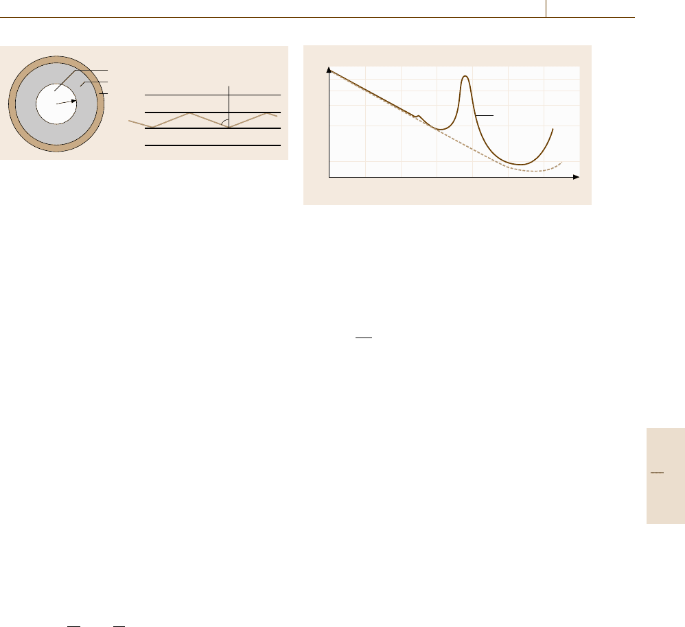
Figure 11.62 shows the measured loss spectrum of
a typical low-loss silica fiber [11.69]. Silica suffers
from absorption due to electronic transitions in the ul-
traviolet region below 170 nm and absorption due to
vibrational transitions in the infrared beyond 2 μm, but
is highly transparent in the visible and near-infrared. In
this region the fundamental attenuation mechanism is
1
0.2
1.0 1.1 1.2 1.3 1.4 1.5 1.6 1.7
Wavelength (μm)
0.8
0.6
0.4
Loss (dB/km)
Loss profile
Intrinsic
loss
Fig. 11.62 Measured loss spectrum of a single-mode silica
fiber. The dashed curve shows the contribution resulting
from Rayleigh scattering (after [11.69])
Rayleigh scattering due to the irregular glass structure.
Intrinsic losses in silica fiber due to Rayleigh scattering
is estimated to be
α
R
=
C
R
λ
4
,
where the constant C
R
is in the range 0.7–0.9dB/
km μm
4
depending on the constituents of the fiber core.
Typical losses in modern fibers is around 0.2dB/km
near 1.55 μm. Conventional silica fiber has absorption
peaks at 1.4, 2.2 and 2.7 μm due to OH vibration modes
and these absorption peaks are sensitive to water con-
tamination.
Attenuation Measurement
There are two general methods for the measurement of
fiber loss; the cut-back method and optical time-domain
reflectometry (OTDR). In any scheme special attention
must be paid to uncertainty arising from the source-
to-fiber coupling. The cut-back method is a destructive
evaluation which neatly avoids the difficulty [11.70]. It
operates in the following way.
•
Couple the light from the source into a long length
of fiber.
•
Measure the light output with a large-area detector.
•
Cut the fiber back by a known length and measure
the change in the light output.
The change in the output is considered to arise from the
attenuation in the cut fiber.
In the case of a single-mode fiber, the fiber may
be cut back to a relatively short length (several me-
ters) where the cladding modes are effectively removed.
However, if the higher mode is near or just beyond
the cut-off, we may need a sufficiently long length of
Part C 11.5